1
APPLICATION
NOTE
BL××FUNCTION
BLOCKS
FOR CODESYS
Sense it! Connect it! Bus it! Solve it!
All brand and product names are trademarks or registered trade marks of the owner
concerned.
Edition 10/2012
© Hans Turck GmbH, Muelheim an der Ruhr
All rights reserved, including those of the translation.
No part of this manual may be reproduced in any form (printed, photocopy, microfilm or any
other process) or processed, duplicated or distributed by means of electronic systems
without written permission of Hans Turck GmbH & Co. KG, Muelheim an der Ruhr.
Subject to alterations without notice
Table of contents
1
CoDeSys - function blocks for programmable gateways
1.1
Installation .......................................................................................................................................................1-2
1.2
General .............................................................................................................................................................1-3
1.3
BL20-function blocks ......................................................................................................................................1-4
1.3.1
BL20-1CNT-24VDC-module ................................................................................................................................................................1-4
1.4
BL20/BL67-function blocks.............................................................................................................................1-8
1.4.1
1.4.2
BLxx-1RS232- and BLxx-1RS482/422-modules............................................................................................................................1-8
BLxx-1SSI-Modul.................................................................................................................................................................................. 1-11
2
Application example for a BLxx_1RSxxx_FB with Hyper Terminal
2.1
General .............................................................................................................................................................2-2
2.1.1
Windows HyperTerminal .....................................................................................................................................................................2-3
2.2
Setting-up the communication parameters..................................................................................................2-4
2.2.1
2.2.2
Setting-up the module parameters in CoDeSys .........................................................................................................................2-4
Setting-up the properties in HyperTerminal................................................................................................................................2-5
2.3
CoDeSys - calling the FB and variable declaration .......................................................................................2-6
2.4
Transmission of data (module → HyperTerminal)........................................................................................2-7
2.5
Reception of data (HyperTerminal → module) .............................................................................................2-8
D301146 - CoDeSys FBs for BL×× 1012
1
1
CoDeSys - function blocks for programmable gateways
1.1
Installation..................................................................................................................................................... 2
1.2
General........................................................................................................................................................... 3
1.3
BL20-function blocks .................................................................................................................................... 4
1.3.1
BL20-1CNT-24VDC-module ..............................................................................................................................................................4
– Variable description ........................................................................................................................................................................4
– Example for the PLC configuration of the module BL20-1CNT.......................................................................................7
1.4
BL20/BL67-function blocks .......................................................................................................................... 8
1.4.1
BLxx-1RS232- and BLxx-1RS482/422-modules..........................................................................................................................8
– Structure of the function block...................................................................................................................................................8
– Variable description ........................................................................................................................................................................9
– Example for the PLC configuration of the module BLxx-1RSxxx ................................................................................. 10
BLxx-1SSI-Modul................................................................................................................................................................................ 11
– Structure of the function block................................................................................................................................................ 11
– Variable description ..................................................................................................................................................................... 11
– Example for the PLC configuration of the module BLxx-1SSI....................................................................................... 13
1.4.2
D301146 - CoDeSys FBs for BL×× 1012
1-1
CoDeSys - function blocks for programmable gateways
1.1
Installation
In order to use the function block described in the next pages, the file "BLxx_PG_FB.lib" has to be copied
into the following Windows folder (choose the drive letter according to the installation path of the
CoDeSys software):
C:\Programs\CommonFiles\CAA-Targets\Turck\BLxx
1-2
D301146 - CoDeSys FBs for BL×× 1012
General
1.2
General
The gateways BL20-PG-×× and BL67-PG-×× support technology modules at the local module bus,
which provide command and control bits for the data exchange via the process data.
In order to use these module functions, so called "handshake" mechanisms have to be programmed in
the user program.
In the following, functions which control this handling are described. The functions are part of the
BLxx_PG_FB.lib. This library is divided into two sub-directories:
1 BL20_PG_FB
with function block BL20_1CNT_FB for the module BL20-1CNT
2 BLxx_PG_FB
with function block BLxx_1RS××_FB for the modules BL××-1RS232 as well as
BL××-1RS422/485 and BL××_1SSI_FB for the module BL××-1SSI
Remark:
A prefix is added to the variable names. This prefix is chosen according to recommendations in the IEC
61131 and of 3S-Smart Software Solutions GmbH.
By means of this prefix the user can identify the variables’ data types:
Example:
xVarName = data type BOOLEAN
bVarName = data type BYTE etc.
D301146 - CoDeSys FBs for BL×× 1012
1-3
CoDeSys - function blocks for programmable gateways
1.3
BL20-function blocks
The function blocks in this sub-directory are only valid for BL20 modules.
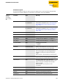
1.3.1
BL20-1CNT-24VDC-module
The function block BL20_1CNT_FB is used for handling the data of the module BL20-1CNT-24VDC in
counter mode or measurement mode.
The function block works with the starting addresses of the counter module’s process in- and output
data. On the one hand, it shows the actual counter or measurement value and on the other hand, the
module’s functions described in the manual "BL20 I/O modules" (D300717) can be controlled.
Figure 1-1:
BL20_1CNT_FB
Variable description
For internal purpose, the process input and process output data are converted into data type BYTE.
Therefore the variables "ptCNTInput" and "ptCNTOutput" are defined as data type POINTER.
Table 1-1:
Variable
description
BL20_1CNT_FB
1-4
Variable
Type
Meaning
ptCNTInput
POINTER TO ARRAY
[0...7] OF BYTE
POINTER to the counter module’s process input
words e.g. ADR(%IW4) or ADR(CNT_IN) →
Example for the PLC configuration of the module
BL20-1CNT (page 1-7).
ptCNTOutput
POINTER TO ARRAY
[0...7] OF BYTE
POINTER to the counter module’s process output
words e.g. ADR(%QW4) or ADR(CNT_OUT). →
Example for the PLC configuration of the module
BL20-1CNT (page 1-7).
xCountOrMeasure
BOOL
The module’s operation mode as chosen in the
PLC configuration:
0 = counter mode
1 = measurement mode
D301146 - CoDeSys FBs for BL×× 1012
BL20-function blocks
Table 1-1:
Variable
description
BL20_1CNT_FB
Variable
Type
Meaning
xSW_GATE
BOOL
Software release for counting or measurement
xCTRL_SYN
BOOL
Release synchronization
xCTRL_DO1
BOOL
Release output DO1
xSET_DO1
BOOL
Control bit output DO1
xCTRL_DO2
BOOL
Release output DO2
xSET_DO2
BOOL
Control bit output DO2
xRES_STS
BOOL
Reset status bits: 0 → 1 start reset
xEXTF_ACK
BOOL
Acknowledgment of diagnostic error
diLOAD_VAL
DINT
for counter mode: Value for "load value directly"
xLOAD_VAL
BOOL
for counter mode: load "load value directly"
diLOAD_PREPARE
DINT
for counter mode: value for "load value in
preparation"
xLOAD_PREPARE
BOOL
for counter mode: load "load value in
preparation"
diCMP_VAL1
DINT
for counter mode: value for "reference value 1"
xLOAD_CMP_VAL1
BOOL
for counter mode: load "reference value 1"
diCMP_VAL2
DINT
for counter mode: value for "reference value 2"
xLOAD_CMP_VAL2
BOOL
for counter mode: load "reference value 2"
udiVAL_INTTIME
UDINT
for measurement mode: value for "integration
time"
xLOAD_INTTIME
BOOL
for measurement mode: load "integration time"
udiVAL_LOLIMIT
UDINT
for measurement mode: value for "lower limit"
xLOAD_LOLIMIT
BOOL
for measurement mode: load "lower limit"
udiVAL_HILIMIT
UDINT
for measurement mode: value for "upper limit"
xLOAD_HILIMIT
BOOL
for measurement mode: load "upper limit"
udiVAL_DO_PARAM
UDINT
Function and behavior output DO1 and DO2
xLOAD_DO_PARAM
BOOL
Change function and behavior output DO1 and
DO2
xSTS_LOAD
BOOL
Load function and behavior output DO1 and DO2
diEncoderValue
DINT
Count value
xERR_24VDC
BOOL
Error bit short-circuit sensor or error at power
supply
D301146 - CoDeSys FBs for BL×× 1012
1-5
CoDeSys - function blocks for programmable gateways
Table 1-1:
Variable
description
BL20_1CNT_FB
1-6
Variable
Type
Meaning
xERR_DO
BOOL
Error bit short-circuit at output DO1
xERR_PARA
BOOL
Error bit parameterization
xERR_LOAD
BOOL
Error bit load procedure
xRES_STS_A
BOOL
Reset status bits active
xSTS_LOAD
BOOL
Load procedure running
xSTS_GATE
BOOL
Status release counter module
xSTS_DI
BOOL
Status hardware input
xSTS_DO1
BOOL
Status hardware output DO1
xSTS_DO2
BOOL
Status software output DO2
xSTS_C_UP
BOOL
Status count direction up
xSTS_C_DN
BOOL
Status count direction down
xSTS_SYN
BOOL
Status synchronization
xSTS_CMP1
BOOL
Status comparator 1
xSTS_CMP2
BOOL
Status comparator 2 2
xSTS_OFLW
BOOL
Status upper count limit
xSTS_UFLW
BOOL
Status lower count limit
xSTS_ND
BOOL
Status zero crossing
wRetVal
WORD
Returned value: Value > 8000h → Error
– 0x8101:
Size of input data ≠ 8 Bytes → abort FB
– 0x8103
Size of output data ≠ 8 Bytes → abort FB
D301146 - CoDeSys FBs for BL×× 1012
BL20-function blocks
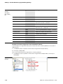
Example for the PLC configuration of the module BL20-1CNT
In this example, the assignment of the process input data to the variable "ptCNTInput" can be done in
different ways:
1 as ADR(CNT_IN), if a symbolic name has been assigned to the input address,
2 or directly as ADR(%IW4)
This is also valid for the process output data in variable "ptCNTOutput":
1 as ADR(CNT_OUT), if a symbolic name has been assigned to the output address,
2 or directly as ADR%QW4)
Figure 1-2:
Example
D301146 - CoDeSys FBs for BL×× 1012
1-7
CoDeSys - function blocks for programmable gateways
1.4
BL20/BL67-function blocks
The function blocks described in the following section can be used for both, BL20 as well as BL67
modules.
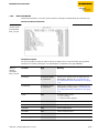
1.4.1
BLxx-1RS232- and BLxx-1RS482/422-modules
The function block BLxx_1RSxxx_FB can be used for the data handling of the interface modules (BL201RS232, BL20-1RS485/422, BL67-1RS232 und BL67-1RS485/422). It supports the simultaneous
transmitting and receiving of data, which means, a full duplex mode, for example with the module
BLxx-1RS232, is possible. As only the in- and output data are evaluated, this function block can be
chosen regardless of the type of interface which is used.
The function block recalls the process input data (ptRxData) and stores them to the data buffer
(ptRxBuffer). The size and the location of the data buffer are determined by the user.
Additionally, the user can define the number of bytes within a telegram (uiMaxRxBuffer).
The same applies for the transmit data.
Structure of the function block
Figure 1-3:
Structure of the
function block
BLxx_1RSxxx_FB
1-8
D301146 - CoDeSys FBs for BL×× 1012
BL20/BL67-function blocks
Variable description
For internal purpose, the process input and process output data are converted into data type BYTE.
Therefore the variables "ptRxData" and "ptTxData" are defined as data type POINTER.
Table 1-2:
Variable
description
BLxx_1RSxxx_
FB
Variable
Type
Meaning
ptRxData
POINTER TO ARRAY
[0...7] OF BYTE
Pointer to the module’s process input data e.g.
ADR(%IW8) or ADR(RS232_RX) → Example for the
PLC configuration of the module BLxx-1RSxxx
(page 1-10).
ptTxData
POINTER TO ARRAY
[0...7] OF BYTE
Pointer to the module’s process output data e.g.
ADR(%IQ8) or ADR(RS232_TX) → Example for the
PLC configuration of the module BLxx-1RSxxx
(page 1-10).
xEnableRx
BOOL
Release for data reception
xEnableTx
BOOL
Release for data transmission
xQuit
BOOL
Acknowledgment of errors
xClr_Buf_Rx
BOOL
Flushing of receive buffer: 0 → 1 and Quit = 1
xClr_Buf_Tx
BOOL
Flushing of transmit buffer: 0 → 1 and Quit = 1
xDisableTxBuffer
BOOL
Disabling transmit buffer:
0 = release;
1 = disable
ptRxBuffer
POINTER TO BYTE
Address of the buffer for receive data within the
PLC. Array of n elements of data type BYTE.
uiMaxRxBytes
UINT
Maximum number of the data byte to be received
within one telegram. Can be changed before a
new job according to the expected telegram
length.
Note: Has to be > 0, if not, data are not received.
ptTxBuffer
POINTER TO BYTE
Address of the buffer for the transmit data within
the PLC. Array of n elements of data type BYTE.
uiMaxTxBytes
UINT
Maximum number of the data byte to be
transmitted within one telegram. Can be changed
before a new job according to the expected
telegram length.
Note: Has to be > 0, if not, data are not
transmitted.
xBusyRx
BOOL
Displays an active data reception.
uiReceivedBytes
UINT
Counter for the received data bytes
xBusyTx
BOOL
Displays an active data transmission
uiSentBytes
UINT
Counter for the transmitted data bytes
D301146 - CoDeSys FBs for BL×× 1012
1-9
CoDeSys - function blocks for programmable gateways
Table 1-2:
Variable
description
BLxx_1RSxxx_
FB
Variable
Type
Meaning
xSentByteNotEmpty
BOOL
-
wRetVal
WORD
Return Value: value > 8000h → error
0×8101
"Size of receive buffer" > the "max. number of
bytes to be received" → abort FB
0×8103
Size of array of input data ≠ 8 Bytes → abort FB
0×8201
"Size of transmit buffer" > the "max. number of
bytes to be sent" → abort FB
0×8203
Size of array of output data ≠ 8 Bytes → abort FB
0×8000
Module not ready for communication
0×8008
Parameter error at module
0×8010
Hardware error at module
0×8020
Error in data flow control
0×8040
Frame error
0×8080
(Receive-)buffer overflow
– error of size variables
– module errors
Example for the PLC configuration of the module BLxx-1RSxxx
In this example, the assignment of the process input data to the variable "ptRxData" can be done in
different ways:
1 as ADR(RS232_RX), if a symbolic name has been assigned to the input address,
2 or directly as ADR(%IW8)
This is also valid for the process output data in variable "ptTxData":
1 as ADR(RS232_TX), if a symbolic name has been assigned to the output address, or directly as
ADR%QW8).
Figure 1-4:
Example
1-10
D301146 - CoDeSys FBs for BL×× 1012
BL20/BL67-function blocks
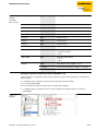
1.4.2
BLxx-1SSI-Modul
The function block BLxx_1SSI_FB is used for the data handling of a module BL20-1SSI and BL67-1SSI.
Structure of the function block
Figure 1-5:
Structure of the
function block
BLxx_1SSI_FB
Variable description
For internal purpose, the process input and process output data are converted into data type BYTE.
Therefore the variables "ptSSIInput" and "ptSSIOutput" are defined as data type POINTER.
Table 1-3:
Variable
description
BLxx_1SSI_FB
Variable
Type
Meaning
ptSSIInput
POINTER TO ARRAY
[0...7] OF BYTE
Pointer to the module’s process input data e.g.
ADR(%IW0) or ADR(SSI_IN) → Example for the
PLC configuration of the module BLxx-1SSI (page
1-13).
ptSSIOutput
POINTER TO ARRAY
[0...7] OF BYTE
Pointer to the module’s process output data e.g.
ADR(%QW0) or ADR(SSI_OUT) → Example for the
PLC configuration of the module BLxx-1SSI (page
1-13).
xStop
BOOL
Communication control:
0 = cyclic reading;
1 = communication stopped
xEnCMP1
BOOL
Release comparison 1
xClrCMP1
BOOL
Delete comparison bit 1
xEnCMP2
BOOL
Release comparison 2
xClrCMP2
BOOL
Delete comparison bit 2
diREG_CMP1
DINT
Comparison value 1
xLOAD_REG_CMP1
BOOL
Load comparison value 1
D301146 - CoDeSys FBs for BL×× 1012
1-11
CoDeSys - function blocks for programmable gateways
Table 1-3:
Variable
description
BLxx_1SSI_FB
1-12
Variable
Type
Meaning
diREG_CMP2
DINT
Comparison value 2
xLOAD_REG_CMP2
BOOL
Load comparison value 2
diREG_LOWER_LIMIT
DINT
Value for lower limit
xLOAD_REG_LOWER_
LIMIT
BOOL
Load value for lower limit
diREG_UPPER_LIMIT
DINT
Value for upper limit
xLOAD_REG_UPPER_
LIMIT
BOOL
Load value for upper limit
xRegWR
BOOL
Release for writing a register: 0 → 1 active
bRegRdAdr
BYTE
Address for reading a register
bRegWrAdr
BYTE
Address for writing a register
diRegWrData
DINT
Data of the register to be written
dwRegRdData
DWORD
Data of the register to be read
bRegRdAdrStat
BYTE
Acknowledge of the register which was read
xRegRdAbort
BOOL
Abort of reading registers
xRegWrAkn
BOOL
Acknowledge WRITE register running
xRegWrAcept
BOOL
Acknowledge WRITE register accepted
xStsCMP1
BOOL
Status bit COMP1:
1 = RegSSIPos = RegCMP1;
0 = RegSSIPos ≠ RegCMP1
xFlagCMP1
BOOL
Status bit COMP1 (latch):
1 = RegSSIPos = RegCMP1;
0 = RegSSIPos ≠ RegCMP1
xRelCMP1
BOOL
Status bit COMP1:
1 = RegSSIPos ≥ RegCMP1;
0 = RegSSIPos < RegCMP1
xStsCMP2
BOOL
Status bit COMP2
1 = RegSSIPos = RegCMP2;
0 = RegSSIPos ≠ RegCMP2
xFlagCMP2
BOOL
Status bit COMP2 (latch):
1 = RegSSIPos = RegCMP2;
0 = RegSSIPos ≠ RegCMP2
xRelCMP2
BOOL
Status bit COMP2
1 = RegSSIPos ≥ RegCMP2;
0 = RegSSIPos < RegCMP2
xSstDN
BOOL
Status count direction down
D301146 - CoDeSys FBs for BL×× 1012
BL20/BL67-function blocks
Table 1-3:
Variable
description
BLxx_1SSI_FB
Variable
Type
Meaning
xStsOflw
BOOL
Status overflow
xStsUflw
BOOL
Status underflow
xStsStop
BOOL
Status communication
xSSIDiag
BOOL
Display: diagnostic message present
xSSISts0
BOOL
Diagnostic bit 0
xSSISts1
BOOL
Diagnostic bit 1
xSSISts2
BOOL
Diagnostic bit 2
xSSISts3
BOOL
Diagnostic bit 3
xERR_SSI
BOOL
Status encoder signal:
1 = error (wire break)
0 = O.K.
xERR_PARA
BOOL
Status parameterization:
1 = error
0 = O.K.
wRetVal
WORD
Return Value: value > 8000h → error
– 0x8101:
Size of array of input data ≠ 8 Bytes → abort FB
– 0x8103
Size of array of output data ≠ 8 Bytes → abort FB
Example for the PLC configuration of the module BLxx-1SSI
In this example, the assignment of the process input data to the variable "ptSSIInput" can be done in
different ways:
1 as ADR(SSI_IN), if a symbolic name has been assigned to the input address,
2 or directly as ADR(%IW0)
This is also valid for the process output data in variable "ptSSI_Output":
1 as ADR(SSI_OUT), if a symbolic name has been assigned to the output address, or directly as
ADR%QW0).
Figure 1-6:
Example
D301146 - CoDeSys FBs for BL×× 1012
1-13
2
Application example for a BLxx_1RSxxx_FB with Hyper Terminal
2.1
General........................................................................................................................................................... 2
2.1.1
Windows HyperTerminal...................................................................................................................................................................3
2.2
Setting-up the communication parameters ............................................................................................... 4
2.2.1
2.2.2
Setting-up the module parameters in CoDeSys .......................................................................................................................4
Setting-up the properties in HyperTerminal..............................................................................................................................5
2.3
CoDeSys - calling the FB and variable declaration ..................................................................................... 6
2.4
Transmission of data (module → HyperTerminal) ..................................................................................... 7
2.5
Reception of data (HyperTerminal → module)........................................................................................... 8
D301146 - CoDeSys FBs for BL×× 1012
2-1
Application example for a BLxx_1RSxxx_FB with Hyper Terminal
2.1
General
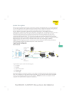
By means of the following example, a RS232-communication between a BL20-station, consisting of a
programmable gateway and amongst others one RS232-module, and a Windows HyperTerminal is
described.
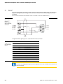
The connection between RS23-module and PC is realized via the PC’s COM-interface:
Figure 2-1:
Connection
between
BL20-1RS232
and D-sub male
connector
11
21
12
22
11 = RxD
21 = TxD
2 = RxD
GND
3 = TxD
8 = CTS
14 = CTS
24 = RTS
13
23
14
24
7 = RTS
SHLD
Assignment of the signal types at a 9-pole Submin-D male connector
Table 1:
Assignment of
the signal types
RS232
Pin- No.
Signal designation
1
DCD
Data Carrier Detect
2
RxD
Receive Data
3
TxD
Transmit Data
4
DTR
Data Terminal Ready
5
GND
Ground
6
DSR
Data Set Ready
7
RTS
Request To Send
8
CTS
Clear To Send
9
RI
Ring Indicator
Note
The table rows highlighted in grey indicate signals that are also available at the terminals of
the base module.
2-2
D301146 - CoDeSys FBs for BL×× 1012
General
2.1.1
Windows HyperTerminal
Windows-HyperTerminal is opened via "Start → (All) Programs → Accessories → Communication
→ HyperTerminal".
Note
Enter your "Area Code". Entering the phone number is not necessary for a serial connection at
the PC.
Enter a user defined connection name in the dialog box „Connection Description“ and define the COM
port, via which the connection between PC and module has to be established.
Figure 2-2:
Windows
HyperTerminal
D301146 - CoDeSys FBs for BL×× 1012
2-3
Application example for a BLxx_1RSxxx_FB with Hyper Terminal
2.2
Setting-up the communication parameters
Note
In order to guarantee an error-free RS232-communication, the communication parameters of
both RS232-nodes (RS232-module and HyperTerminal) have to be identical.
2.2.1
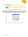
Setting-up the module parameters in CoDeSys
The RS232-module’s parameter definition is done in the PLC configuration.
Mark the entry BLxx-IO [Slot] and select the module BL20-1RS232 under „Selected Modules“ in the
"Input/Output“-tab.
After this, open the parameterization dialog box „Module Properties“ via the „Properties“ button.
Figure 2-3:
IO module,
properties
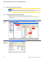
Figure 2-4:
Parameterization in "Module
Properties"
2-4
D301146 - CoDeSys FBs for BL×× 1012
Setting-up the communication parameters
2.2.2
Setting-up the properties in HyperTerminal
Configure HyperTerminal according to the application ("File → Properties"). The configuration is only
possible if the connection is inactive. If necessary, an active communication has to be disconnected via
"Call → Disconnect" first.
Note
Please note that the configuration for the RS232-module and for the HyperTerminal are
identical. Otherwise an error-free communication can not be guaranteed.
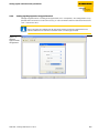
Figure 2-5:
Windows
HyperTerminal,
configuration
D301146 - CoDeSys FBs for BL×× 1012
2-5
Application example for a BLxx_1RSxxx_FB with Hyper Terminal
2.3
CoDeSys - calling the FB and variable declaration
Call the function block BLxx_RSxxx_FB for RS232-communication in the PLC_PRG.
If, in the PLC configuration, variables have been defined for the module’s in- and output word (here in
this example: "RS232_RX" and "RS232_TX"), then those variables have to be assigned to the pointers of
the receive and transmit data buffers ("ptRxData" and "ptTxData", see also page 1-9).
Figure 2-6:
Variable declaration and
usage in the FB
All other variables are already defined within the function block.
Note
It is also important to enter the maximum number or data to be transmitted and received in
"uiMaxTxByte" or respectively "uiMaxRxByte". Without these entries no data is exchanged.
Figure 2-7:
Max. number of
data to be
transmitted and
received
2-6
D301146 - CoDeSys FBs for BL×× 1012
Transmission of data (module → HyperTerminal)
2.4
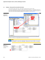
Transmission of data (module → HyperTerminal)
1 The data to be transmitted is written to the transmit buffer "TX_Buffer".
2 Then, the transmission has to be enabled in the FB/ module. Set the variable "xEnableTx" to TRUE.
3 HyperTerminal shows the received data in ASCII code.
Figure 2-8:
Transmission
1
2
3
D301146 - CoDeSys FBs for BL×× 1012
2-7
Application example for a BLxx_1RSxxx_FB with Hyper Terminal
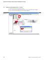
2.5
Reception of data (HyperTerminal → module)
1 Write the data to be sent into HyperTerminal.
2 Then, enable the data reception in the FB/ module. Set the variable "xEnableRx" to TRUE.
3 The received data will be shown in the receive buffer „RxBuffer".
Figure 2-9:
Reception
3
2
1
2-8
D301146 - CoDeSys FBs for BL×× 1012
Hans Turck GmbH & Co. KG
45472 Mülheim an der Ruhr
Germany
Witzlebenstraße 7
Tel. +49 (0) 208 4952-0
Fax +49 (0) 208 4952-264
E-Mail [email protected]
Internet www.turck.com
D301146 1012
www.turck.com


![Overview cPR67 and cPR84 [v00]](http://vs1.manualzilla.com/store/data/005648847_1-d158a5d3d4b92d14c7a3179652b88ffd-150x150.png)