1
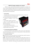
MINCO A3 genset controller user’s manual
MINCO A3 controller adopts high performance microprocessor and industrial class devices,
with high and bright LED display and 96 X 96 mm standard shell. It has the properties of compact
structure, marked display and easily install, The controller can control the genset to start and
stop ,
detect and measure the work state of genset, and realize the auto-protect function. And it can also
provide autostart and ATS control functions.
I. Characteristic
1. The engine controller control the genset to run or stop by either press-key, or outside switch.
2. Provids remote start port, can set the delay start and stop. It
can control the the genset to auto start and stop.
3. Relay output touching capacities 10A.
4. ATS function, control genset supply or normal supply.
5. There are two kinds connecting ways of Water temperature,
oil pressure, option input. That’s analog input or switch alarm
input.
6. Auto record the running times of genset.
7. Protection function: low oil pressure, high coolant, over speed,
emergency stop and over crank.
Ⅱ. The front-panel function explanation
The front panel of MINCO A3 engine controller has 5 LED, 6 press-keys and 12 indicator lights.
The press-keys control genset to start or stop and set working parameters, the indicator lights indicate
the state of controller and failure of genset.
1. The control key instruction
RUN : When press key, the above green light become always bright, indicate controller is be placed in
"running", directly start the generator manually , and keep running.
AUTO
: When press this key, the above yellow LED become always bright, indicate controller is be
placed in "automatic state", the controller receive the "remote start" switch signal, if this switch is close,
then delay to starte the generator; Otherwise will delay to stop machine. To realize the auto-start
control of gen-set, "Remote start" switch signal can be provided by the detect module of the normal
supply or timer. In order to realize an engine automation controlling staying.
-1-
RESET :When press this key, the above red LED always bright, indicate controller is be placed in
"STOP/RESET" state, if at this time generator just in the running, press this key once, the engine will
shut down normally; press this key two times continuously, the engine will stop immediately.
+ 、 - :The key is used to change the LED display content and to change parameter setting under
setup circumstances.
SET
: The key is used to enter into or exit parameter settings.
2. Instruction of the indicator light
The front-panel of the controller has 12 indicator lights, they denote the state or alarm of controller
and generator.
Five of them showed LED statement:
When Press +
、 -
key, station will be to changed display in 5 LED. They will be
displayed the different content, and corresponging every LED display the only content.
1) HZ— Denote genset frequency. (Unit: HZ)
2) TEMP—Denote the current engine coolant temperature. (Unit: ℃ ) If you do not take the water
temperature sensor, the show "---".
3) OIL.P— Denote the current engine oil pressure. (Unit: kpa ) If you do not take the oil pressure
sensor, the show "---".
4) BATT.V—Denote the current battery voltage. (Unit: V )
5) HOURS—Denote current already working engine time. (Unit: Hour)
There is five indicator light of statement: LOADING, REMOTE (MAINS STATE), START,
AUTO, RESET/STOP.
The one light of alarm: If the controller MINCO A3 "alarm switch" (port 24) interface on the input
with battery “-“ to short, 5 seconds after a delayed report to the alarm after the bright lights, but it will
not protect the engine shutdown.
.
The one light of fault: when the engine appear to operation failure , it will lead the MINCO A3
controller control engine shut down to protect the engine, at the same time, 5 high-light LED denote the
failure code . The reason which led to shut down the machine for protection can be judged according to
the failure code.
Failure code and corresponding failure cause:
E――01: over crank;
E――02: emergency stop;
E――03: over speed;
E――04: loss speed;
E――05: high coolant;
E――06: low oil pressure;
E――07: null ;
E――08: low battery voltage;
-2-
If the machine is conk out, then will lead the machine to shut down for protection, at the same time,
the malfunction reason will be locked, and the motor can not be start again. until the malfunction was
solved, and then pree the key RESET .Then you can start the motor again.
Ⅲ. Parameter setup
when press SET key, it will enter into the setting state, two LED on the left will show “00”-“20”
twenty-one in total codes, three LED on the right will show corresponding parametric content . The
parameter will increase or decrease according to pressing the
+
or
-
key. And according to
press SET key, the set parameter will be saved and display next parameter ( the parameter code add
one). Continue to press SET key, until all parameters were set, finally exit parameters setting state. On
the setting status, if you do not press anything in the thirty second, the setting state will be exit , and
return to the measurement state and to normal display.
00――coolant temperature upper limit;
01――oil pressure lower limit;
02――battery voltage lower limit;
03――frequency upper limit;
04――frequency lower limit ;
05――trip frequency;
06――coolant temperature adjust ;
07――oil pressure adjust ;
08――battery voltage adjust ;
09―― null ;
10――delay of no power to load ;
11――delay of warm up ;
12――delay of Energize To Stop (ETS) ;
13――delay of remote start;
14――delay of retransform;
15――delay of cool down ;
16 ――delay of Idle speed on starting;
17――delay of idle speed on stopping;
18 ――control parameter 1 ;
19――control parameter 2
20 ――control parameter 3 ;
Coolant temperature upper limit: If the coolant temperature was selected the analog sensor to
give alarm, when coolant temperature exceeds this upper limit, it will lead the engine protection to shut
down; (Default:96)
Oil pressure lower limit: If oil pressure was selected to give alarm by the oil pressure sensor.
when oil pressure is lower than the lower limit, it will lead the engine to shut down for protection;
(Default:200)
Battery voltage lower limit: When the battery voltage is lower than lower limit voltage, it will
alarm but will not shut down the engine. (Default:10.5)
Frequency upper limit: When the engine frequency is higher than upper limit, it will lead the
engine to shut down for the protection.; and instruct the over speed malfunction;(Default:55)
-3-
Trip frequency: When the genset frequency is higher this limit, then, indicate the engine start
successfully, and stop cranking the motor ;( Default: 13.50)
Frequency lower limit: When the engine frequency is lower than this limit, it will lead the
engine to shut down for the protection; and instruct the over speed malfunction ;( Default: 47)
Coolant temperature adjust , oil pressure adjust , battery voltage adjust: when you measure
the water temperature , oil pressure , battery voltage, it may bring some measurement error ,this error
value was allowed to adjust in a range of 10% more or less in MINCO A3. Especially, the coolant or
oil-pressure sensor maybe positive modulus (the sensor output enhances with input enhancing), or may
be minus modulus (the sensor output diminishes with input enhancing) .The effects that arised from
imcreasing or decreasing adjusting value will depend on the actual circumstance;
The ways of coolant temperature adjustment: Enter into setting interface; the initialization is “0”.
Press
+ or
-
once, The current show value will be reduced or added for 2 units. If the screen
display “4 units were higher”,please set “+2.”
The ways of oil pressure, battery voltage adjustment: Enter into setting interface, the
initialization is “0”, Press + or
-
once, The current show value will be added
or reduced for 2
units. If the screen display “4 units were higher”, please set “-2.”
Delay of no power to load: between mains supply output and genset supply output there is a
delay, during the delay no power supply to load. (factory default value: 2 s)
Delay of warm up:When start successful and after idle. There is a delay to loading, it can make the
genset reach to optimal work state, Reduce machine wear and tear. (Default:10 s)
Delay of Energize To Stop (ETS): Set to “0”, fuel mode is “Energize to Run” (ETR), fuel beginning
starting until shutdown so far;
If set to “nonzero”, fuel mode is “Energize to Stop” (ETS). At this time, the output of “fuel” is
equivalent with the stopping of the machine. While stopping the machine, start the delay and the relay
of “fuel” have output. When delay is over, the relay of "fuel" stop output.(Default:30 s)
Delay of remote start: In the "auto" state of controller, When the normal power failure was
detected begin the delay, The engine start when delay finished.(Default:3)
Delay of retransform: Start delay of retransform when the engine work with onload and the
remote start switch was disconnected. The engine will dis-onload and no-loading to work when delay
of retransform finished.(Default:5)
Delay of cool down: When the controller is in "auto" state and the "remote start" switch
disconnect , as well as the genset was load-off. The genset will work with no-loading. The genset will
shutdown after the delay is over. (Default:20)
Delay of Idle Speed when Starting : Start to idle speed delay when the machine start
successfully. Start to ACCeleration when delay finished .(Default:10)
-4-
Delay of Idle Speed when Stopping: In the AUTO statement, the idle speed delay will begin when
the delay of DECeleration was finished. Fuel stopping when delay finished.(Default:15)
Control parameter 1: (Default: 0 )
“0”―― testing low oil pressue input when start-up, switching-on mode is NC (normal closed).
“1”―― start-up not testing low oil pressure input, switching-on mode is NC.
“2”―― testing low oil pressue input when start-up, switching-on by pulse (To maintain the closed
off after two seconds).
“3”―― start-up not testing low oil pressure input, switching-on by pulse.
Control parameter 2 (default "0" )
“0”- high temp. alarm by switch input, low oil pressure alarm by switch input ;
“1”- high temp. alarm by temp. sensor, low oil pressure alarm by switch input ;
“2”- high temp. alarm by switch input, low oil pressure alarm by oil sensor ;
“3”- high temp. alarm by temp. senso, low oil pressure alarm by oil sensor;
Control parameter 3: Only be set by manufacturer, don’t set them by yourself please !
Ⅳ. The controller interface explaination
1. Power Supply (range: DC8~36 v)
Port 1――connect battery “-” pole (GND).
Port 2――connect battery “+” pole
If power source polarity meet on the contrary, since the inside connect have a protecting diode,
in general it will not breakdown the controller.
2. Analog input:
Port 7――coolant temperature sensor input.
Port 8――oil pressure sensor input
3. Switch input (That entering adds photoelectric isolator, the short circuit is effective with
GND)
Port 20――remote start;
Port 21――emergency stop; (When emergency or repairing the machine, the machine will
not start when lock and close this port.)
Port 22――high coolant temperature;
Port 23――low oil pressure;
Port 24――alarm switch input;
4. Relay output (Relay isolator , touching capacities 10A/250V or 10A/30V )
Port 3――alarm output;
-5-
Port 4――idle NC (closed when idling, opened when rate speed);
Port 5――idle NO (opened when idling, closed when rate speed);
Port 6――idle comm;
Port 13――fuel (stop );
Port 14――crank ;
Port 15――common ; The “fuel” and “crank” relay have one contact connect the “comm ”.
Port 16/17――mains supply;
Port 18/19 ――genset supply ;
5. AC voltage input:
Port 9、Port 10――mains voltage input, to determine whether or not the normal
electricity(Input range: AC70-300 v).
Port 11、Port 12――genset voltage input, used to detect frequency (Input range: AC25-300
v).
Explanation:
1. All of relay output touching capacities is 10A/250V or 10A/30V , When over this capacities,
you need to plus the current absorption electric circuit in outside wiring, otherwise it will
probably influence controller to work normally.
2. If MINCOA3 set to Energize To Stop (ETS), and the controller in the RESET(stop) state, when
press the RESET button every time, the “fuel” relay output has output and begin ETS delay.
when the delay overed, the “fuel” relay stop output.
3. When need to achieve auto-start function, "remote" port and "mains voltage" port connection
may be required to choose. Their relationship is: when the “remote” port not connected (empty),
with or without mains normal, since the genset will not start.when to short the “remote” and
negative side of the battery, the unit is activated by the decision whether or not there is have
mains.
Therefore, the application of the usual (one mains and one emergency power supply),
will short the “remote” port and negative side of the battery, at this time if there is without
mains, and then start the unit with switch on. When mains restore, genset will unloading and
cool down.
But the MINCO A3 only test there is where or not "mains voltage" input, if need to the
mains for a better quality of detection, or at the scene of mains is not city normal, then can not
connect the “mains voltage”, will input the other start signals. If at this time “remote” short with
negative side of the battery, the unit start and will switch on loading, and will unloading and
delayed shutdown when the port disconnect.
4. All the coolant temperature, oil pressure sensor and alarm sensor that GuiLin MINCO
electronic CO.,LTD provides are electric resistance type sensor. For electric resistance type
sensor, the measure method needs to connect allotted resistance. The MINCO A3 controller has
taken over three allotted resistance already inside, so do not need to connect the allotted
resistance outside.
-6-
Ⅴ. Size of form and outside wiring diagram
Size of form:96 mm (Width) ×96 mm (Height) ×8.5 mm(Depth)
(front panel)
84 mm (Width) ×84 mm (Height) ×48 mm (Depth)(back shell)
Hole size of panel:85+1 mm (width) × 85+1 mm(height)
VI. Mode of start and stop:
There are two ways genset can be started : First, press the RUN button on the panel, it will
start engines immediately, and has been kept running; second, press the AUTO button, the controller
is in the "automatic state" , if the "remote start" switch input signal closure at this time, after the delay
of remote start, the engine will start.
During the starting of engine, the starting light flashes when pressing the run button (the auto
light flashes when pressing the auto button), after the engine starts successfully, the light is always
bright. After the delay of idle when stop and warm up, the engine is ready to onload, but whether the
engine is onloading is decided by the "remote start" Switch input, as long as "Remote Start" is not
closed, the engine is not automatically onloading. Therefore, users should pay more attention to this
point, auto start will auto onload, but if starting by pressing the “RUN” button, that would not
necessarily onload. If the application needs pressing the RUN button to start the engine by hand, we
must short the “remote start” switching to “GND”. While the delay of “warm up” happens, onloading
light flashes. After the delay of “warm up”, onloading light is always bright, the engine runs with load.
If the onloading condition is not satisfied, then the onloading light crushes out and the engine runs with
no load.
"Remote start" connects the normal power supply detection module generally, also can connect
timers or other special devices, to achieve auto-start generator setting and onloading or other functions.
Stop the genset have three ways:
1) Cool down mode at “auto” state. If the "remote start" signal disconnects, it’s unloading after
retransfer delay, after the delay of cool down the engine runs with no load, begins idle for stop, then
stop the machine after the delay of idle for stop.
2) Press the RESET button on the panel, the controller stops normally, and will immediately unload,
and idle to stop, stop the machine after the delay of idle. The indicating light of RESET was flashing
-7-
in the process of Idling, after the machine stops, the light always shine.
2) Emergency stop, will immediately unload and stop. "Emergency stop" signal switch be closed and
the engine failure would lead to an emergency stop. There is a situation another, if press RESET
button again when normally stop machine by press RESET key on the front panel, then bypass
idling to stop immediately.
GuiLin Minco Electronic Co., Ltd. CHINA
GuiLin Glminco Intelligent Control S&T Co., Ltd.
ADD: Building B-216, Venture park of returned Scholars, Guilin high-tech zone, GuangXi, CHINA
Tel: +86-773-5812281 5828281
Fax: +86-773-5828281
E-mail: [email protected] [email protected]
Http: //www.glminco.com
Appendix 1 : Outside wiring diagram(Auto start, Auto Transform Switch state)
:
-8-
Appendix 2 : MINCO A3 front & back panel diagram
-9-