1
GE Infrastructure
Sensing
Druck DBC 150/650 Series
Dry block temperature calibrator
User manual - K400
[EN]
[FR]
[DE]
[IT]
[PT]
[ES]
English
French
German
Italian
Portuguese
Spanish
1 ..... 56
TBA
TBA
TBA
TBA
TBA
© 2005 General Electric Company. All rights reserved.
Introduction
•
This technical manual provides operating instructions for the Druck
DBC Series of Dry Well Calibrators.
Safety
•
•
•
The manufacturer has designed this equipment to be safe when
operated using the procedures detailed in this manual. Do not use this
equipment for any other purpose than that stated.
This publication contains operating and safety instructions that must be
followed to ensure safe operation and to maintain the equipment in a
safe condition. The safety instructions are either warnings or cautions
issued to protect the user and the equipment from injury or damage.
Use suitably qualified * technicians and good engineering practice for
all procedures in this publication.
Test leads
•
Only use the test leads supplied with the instrument, do not use these
test leads with any other equipment.
Power isolation
•
Access to the power supply isolator switch must not be obstructed.
Toxic Materials
•
There are no known toxic materials used in construction of this
equipment.
Maintenance
•
The equipment must be maintained using the procedures in this
publication. Further manufacturer’s procedures should be carried out
by authorized service agents or the manufacturer’s service
departments.
Technical Advice
•
For technical advice contact the manufacturer.
*A qualified technician must have the necessary technical knowledge,
documentation, special test equipment and tools to carry out the required
work on this equipment.
This equipment meets the requirements of all relevant
European safety directives. The equipment carries the CE
mark.
K400 Issue No. 1
i
TRACEABILITY AND CALIBRATION REPORT
•
Each DBC instrument is supplied as standard with a calibration report,
declaring traceability to a National or International standard.
WARRANTY AND LIABILITY
1
Our equipment is guaranteed against defective material and
workmanship during the warranty period. Claims under warranty
can be made by returning the equipment, prepaid, to our factory. The
equipment will be replaced, repaired or adjusted at our discretion.
2
The liability of GE is restricted to that given under our warranty. No
responsibility is accepted for damage, loss or other expense
incurred through the sale or use of our equipment.
3
Under no circumstances will GE be liable for any special incidental
or consequential damage.
Symbols
The following symbols are used to identify hazards on the instrument:
This symbol, on the instrument, indicates that the user
should refer to the user manual.
This symbol, on the instrument, indicates a very hot
surface that must not be touched.
K400 Issue No. 1
ii
Safety Instructions
This instrument should only be used by suitably qualified * technicians
During operation observe the following safety instructions:
1
USE the instrument in vertical position only.
2
DO NOT place any object on the protection grid of the dry well.
3
DO NOT put any liquid into the dry well and/or on the inserts.
4
DO NOT use fluids to clean the dry well and/or the inserts.
5
BEFORE any maintenance activity, WAIT for the instrument to cool
to ambient temperature (keep the instrument switched on, to allow
the cooling fan to operate).
6
DO NOT touch the protection grid until it has cooled to ambient
temperature).
7
The instrument must be at ambient temperature before storing in any
transit case or packing system.
8
DO NOT use this instrument near inflammable liquids or in
Hazardous areas.
9
DO NOT place either your hands, or any other object, into the dry
well.
10
Before use, REMOVE all traces of contamination from the device
under test.
11
During normal operation, this instrument could reach high
temperatures.
12
Always observe all the safety instructions.
*A qualified technician must have the necessary technical knowledge,
documentation, special test equipment and tools to carry out the required
work on this equipment.
Abbreviations
The following abbreviations are used in this manual; the
abbreviations are the same in the singular and plural.
BLK
CJ
DBC
in
mm
RDG
T/C
TC
block
Cold Junction
Dry Block Calibrator
inch
millimetre
reading
Thermocouple
Temperature Calibrator
K400 Issue No. 1
ent
CJC
°C
mA
mV
RTD
V
TS
enter
Cold Junction Compensation
Degrees Centigrade
milliampere
millivolt
Resistive Temperature Device
Volt
Temperature Source
iii
TABLE OF CONTENTS
Introduction .................................................................................. .......... i
Safety .......................................................................................... .......... i
Traceability and Calibration Report.............................................. .......... ii
Symbols ....................................................................................... .......... ii
Safety Instructions........................................................................ .......... iii
Index .......................................................................................... ..........iv
Standard and optional accessories............................................... .......... vii
1
INTRODUCTION ............................................................... ..........1
1.1
Automatic calibration ......................................................... ..........2
1.2
Parts identification ............................................................. ..........2
2
INSTALLATION.................................................................. ..........4
2.1
Preparation ........................................................................ ..........4
2.2
Power Supply..................................................................... ..........4
2.3
Temperature Probes........................................................... ..........4
2.4
Electrical Connections........................................................ ..........6
3
OPERATION...................................................................... ..........11
3.1
Key-pad Functions............................................................. ..........11
3.2
Operating Displays............................................................. ..........13
Menu selection screen....................................................... ..........13
System Set-up screen........................................................ ..........13
Working screen................................................................... ..........13
Help/Info screen................................................................. ..........14
Self-test screen.................................................................. ..........14
3.3
Functional Modes............................................................... .......... 15
Reading of the generated temperature.............................. ..........15
Dual display - (generated temperature and an input test).. ..........15
3.4
Temperature Reference Selection...................................... ..........16
Internal reference probe..................................................... ..........16
External reference probe.................................................... ..........16
3.5
System Set-up .................................................................. ..........18
Language settings.............................................................. ..........18
Temperature unit settings................................................... ..........18
Key-pad audio signal.......................................................... ..........19
Digital Interface settings..................................................... ..........19
K400 Issue No. 1
iv
Printer settings................................................................... ..........20
Calibration.......................................................................... ..........20
Protection code.................................................................. ..........21
3.6
Testing Modes.................................................................... ..........22
Direct mode........................................................................ ..........22
Step mode.......................................................................... ..........23
Fixed step selection............................................................ ..........23
Programmable step selection............................................. ..........24
Ramp mode........................................................................ ..........25
Preset values mode............................................................ ..........26
3.7
Measuring an Input ............................................................ ..........27
Switch test.......................................................................... ..........27
Thermocouple testing......................................................... ..........28
Internal............................................................................... ..........29
Setting Cold Junction Compensation................................. ..........29
Direct ................................................................................. ..........30
CAL mode.......................................................................... ..........30
Absolute............................................................................. ..........31
% of span............................................................................ ..........31
% of reading....................................................................... ..........32
RTD measurements........................................................... ..........33
Direct ................................................................................. ..........34
CAL mode.......................................................................... ..........34
Absolute............................................................................. ..........35
% of span............................................................................ ..........35
% of reading....................................................................... ..........36
Current measurements....................................................... ..........37
Direct ................................................................................. ..........37
CAL ................................................................................... ..........38
Voltage measurements (high level).................................... ..........39
Direct ................................................................................. ..........39
CAL ................................................................................... ..........40
Voltage measurements (low level)...................................... ..........41
Resistance measurements................................................. ..........42
4
SERIAL COMMUNICATION ............................................. ..........43
K400 Issue No. 1
v
4.1
DBC Series - Serial Commands Protocol .......................... ..........43
5
CALIBRATION .................................................................. ..........48
Calibration of the Standard Reference Probe Input ..................... ..........48
Calibration of the External Reference Probe ............................... ..........49
Calibration of the Internal Dry Well Sensor.................................. ..........49
Calibration of the Millivolt Input Range ........................................ ..........50
Calibration of the Volt Input Range .............................................. ..........51
Calibration of the mA Input Range .............................................. ..........51
Calibration of the Ohm Input Range ............................................ ..........52
6
FAULT FINDING ............................................................... ..........53
7
MAINTENANCE................................................................. ..........54
7.1
Cleaning Instructions.......................................................... ..........54
8
TECHNICAL SPECIFICATION ......................................... ..........55
8.1
Standard Specification........................................................ ..........55
8.2
Common Specification ....................................................... ..........55
8.3
Electrical Input Specification (DBC-TC models)................ ..........56
K400 Issue No. 1
vi
STANDARD ACCESSORIES DBC-TC series
The DBC-TC series is supplied with the following standard accessories:
•
Operating manual
•
Set of leads for:
2 test leads and 2 clamps for switch connection
6 test leads and 6 clamps for connection of electrical signal
•
Power supply cable
•
Removable insert with 3 holes (5, 6.6, 9.8 mm diameter), (3/16, 1/4,
3/8 in. diameter for USA)
•
Tool for extraction of removable insert
•
RS232 interface cable (1.5 metre, 5 pin/5 pin)
•
Traceable calibration certificate
•
2 spare fuses (see page 4 for more information)
OPTIONAL ACCESSORIES DBC-TC series
•
Option B1 for DBC 150, reference probe type PT 100, range –50°C
to +400°C
•
Option B2 for DBC 650, reference probe type PT 100, range +50°C
to +650°C
•
Option B3, temperature probe type PT 100, range –50°C to +650°C.
•
Option D, fast cooling device
•
Option E, aluminium transit case
•
Option C1/C2, insert with 2 holes (5 and 13 mm diameter), (3/16,
1/2 in. diameter for USA)
•
Option C3/C4, insert with 4 holes (3.4, 5, 5, 8.2 mm diameter), (1/8,
3/16, 3/16 and 5/16 in. diameter for USA)
•
Option C5/C6, blank insert
•
Option C7/C8, insert with special holes.
K400 Issue No. 1
vii
STANDARD ACCESSORIES DBC-TS series
The DBC-TC series is supplied with the following standard accessories:
•
Operating manual
•
Set of leads for:
2 test leads and 2 clamps for switch connection
•
Power supply cable
•
Removable insert with 3 holes (5, 6.6, 9.8 mm diameter), (3/16, 1/4,
3/8 in. diameter for USA)
•
Tool for extraction of removable insert
•
RS232 interface cable (1.5 metre, 5 pin/5 pin)
•
Traceable calibration certificate
•
2 spare fuses (see page 4 for more information)
OPTIONAL ACCESSORIES DBC-TS series
•
Option B1 for DBC 150, reference probe type PT 100, range –50°C
to +400°C
•
Option B2 for DBC 650, reference probe type PT 100, range +50°C
to +650°C
•
Option B3, temperature probe type PT 100, range –50°C to +650°C.
•
Option D, fast cooling device
•
Option E, aluminium transit case
•
Option C1/C2, insert with 2 holes (5 and 13 mm diameter), (3/16,
1/2 in. diameter for USA)
•
Option C3/C4, insert with 4 holes (3.4, 5, 5, 8.2 mm diameter), (1/8,
3/16, 3/16 and 5/16 in. diameter for USA)
•
Option C5/C6, blank insert
•
Option C7/C8, insert with special holes.
K400 Issue No. 1
viii
1
INTRODUCTION
The DBC series of temperature calibrators test and calibrate temperature devices.
The series comprises two types: a TS (Temperature Source) and a TC
(Temperature Calibrator). Multilingual firmware provides a menu-driven user
interface in English, French, German, Italian, Spanish and Portuguese. An RS232
digital interface, supplied as standard, enables remote operation of the instrument
from a compatible computer.
TS (Temperature Source)
The DBC-TS generates stable temperatures and accurately measures the
temperature of the dry well. It provides an automatic switch test facility.
There are two models of the DBC-TS, providing the same operating capabilities at
different temperature ranges:
• DBC 150-TS : -45°C below ambient temperature to +150°C.
• DBC 650-TS : +50°C to +650°C.
This series of calibrators uses the GE technology temperature controller, providing
high performance temperature stability and accuracy. Temperature generation can
be controlled either in manual mode (direct) or automatic with ramping, stepping or
preset functions. The dry well temperature can be measured either with the internal
probe or with an external certified reference probe. The key-pad, display and
electrical connections enable the user to carry out test procedures for RTD and
thermal switches with a hysteresis calculation.
TC (Temperature Calibrator)
The DBC-TC generates stable temperatures and accurately measures the
temperature of the dry well. It measures process signals from the temperature
devices under test.
There are two models of this series, providing the same operating capabilities at
different temperature ranges:
• DBC 150-TC : -45°C below ambient temperature to +150°C.
• DBC 650-TC : +50°C to +650°C.
This series of calibrators uses the GE technology temperature controller, providing
high performance temperature stability and accuracy. Temperature generation can
be controlled either in manual mode (direct) or automatic with ramping, stepping or
preset functions. The dry well temperature can be measured either with the internal
probe or with an external certified reference probe.
The key-pad, display and electrical connections enable the user to carry out test
procedures for thermocouples, RTD, switches, temperature transmitters and
converters, regulators. Both TC models contain a switch test function with a
hysteresis calculation. This Input/Measure facility enables direct connection and
reading of thermocouples, RTD, Voltages, Current and Resistance: the dual display
can simultaneously show the generated temperature (with internal or external
K400 Issue No. 1
1
reference) and a possible electrical feedback from a device under test (i. e.
temperature probes, temperature transmitters). An error calculation, with scaling
function, allows the user to check immediately the accuracy specification of the unit
under test. A 24 V auxiliary excitation provides power for temperature transmitters
under test.
1.1
Automatic Calibration
An RS232 computer interface enables a Calibration Management Software to
provide automatic calibration procedures, typically with the following capabilities:
• Creation of instrument details
• Creation of test procedures and work orders
• Analysis of devices due for calibration
• Printing of calibration reports
• Export functions
Refer to section 4 SERIAL COMMUNICATION for remote control of this instrument.
1.2
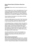
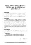
Parts Identification
Key to Figure 1-1
Description
Fig no.
1
Dry well with insert
2
Protection grid
3
Carrying handle
4
4 mm socket for T/C, RTD and ohm connection, with CJ compensation
6
Tactile key-pad for direct selection of all the operating function (ramps, steps, preset
values, switch test, help, set-up) and to set temperature values
Cooling fan
7
Support feet (4)
5
9
Protection fuse (115 Vac 2x12.5 AT and 230 Vac 2x6.3 AT for DBC 650
(115 Vac 2x1.6 AT and 230 Vac 2x3.15 AT for DBC 150)
Main power selector 100 - 120 Vac and 220 - 240 Vac, 50/60 Hz
10
Power supply on/off switch
11
Main power socket: to connect the standard power cable
12
RS232 serial communications interface
8
14
Cursor (arrow) keys to select operating functions from the main menu and to move the
selection cursor through the menus
Digital display with Multi-language user interface
15
Switch test connection, suitable to connect test leads supplied as standard
16
4 mm socket for voltage and current input with 24V dc auxiliary excitation
17
Lemo connection for external reference probe: suitable for connecting PT 100 probes
with 3 or 4 wires, supplied with standard mating connector ( B1, B2 and B3 options)
13
2
K400 Issue No. 1
17
1
16
2
3
15
14
13
4
5
17
DBC-TS
15
12
6
7
9
8
10
11
Figure 1-1
K400 Issue No. 1
3
2
INSTALLATION
2.1 Preparation
General
•
Remove the instrument from the carrying case and use it on a flat, stable
surface. To avoid any possible damage, either to the instrument or the unit
under test, the dry well of the instrument must be used in the vertical position.
•
The fan system at the base of the instrument must be free from any obstruction.
•
The dry well must be completely clean.
•
Carefully read the SAFETY section of this manual.
2.2 Power Supply
CAUTION:
BEFORE OPERATING, CHECK THAT THE POWER SUPPLY SELECTOR SWITCH
SETTING MATCHES THE POWER SUPPLY VOLTAGE.
The DBC series of calibrators operate from an a. c. power supply of 100 to 120 Vac
or 220 to 240 Vac, 50-60 Hz.
CAUTIONS:
1
THE POWER SUPPLY MUST PROVIDE CONNECTION TO A PROTECTIVE GROUND
TERMINAL.
2
THE INSTRUMENT MUST , AT ALL TIMES, BE CONNECTED TO THE SUPPLY EARTH
(GROUND).
2.3 Temperature Probes
WARNING
AFTER USE, THE PROBES WILL BE VERY HOT. HANDLE WITH
CARE AND WAIT FOR THE PROBES TO COOL COMPLETELY.
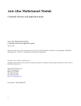
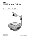
The temperature probe to be tested must be correctly placed in the dry well to
produce accurate test results:
•
•
•
Check the probe diameter and operating range and use reduction inserts with
the correct sized holes (the hole diameter should comply with EA-10/13
guidelines). A large temperature difference between probe and dry well causes
large measuring errors. This difference increases as the difference between
the diameters increases.
Always clean the probes, before use.
Do not force the probes into the dry well, insert the probe down to the bottom of
the dry well.
4
K400 Issue No. 1
When testing a probe with a certified reference probe, place both probes close
together and at the same depth.
YES
*
160mm
50
mm
Calibration
zone
NO
Reduction
insert
•
NO
YES
NO
YES
Internal reference probe
* dimension should comply with EA-10/13 guidelines - for temperature
ranges -80° C to +660°C maximum 0.5mm
IMPORTANT NOTE
Reduction inserts with special holes could be necessary when carrying out a
calibration procedure on temperature device with specific mechanical
dimensions. Refer to GE for details of specific application solutions.
K400 Issue No. 1
5
2.4
•
Electrical Connections
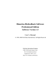
Connection of a Thermocouple sensor
-
+
24V Out
35mA max
V IN
Ref RTD
35mA
max
mA IN
0V
X MTR
C AT I
max 30V
•
Use of screw connections for T/C wires
1
2
3
4
6
K400 Issue No. 1
•
Connection of a 3-wire RTD.
24V Out
35mA max
V IN
Ref RTD
35mA
max
0V
mA IN
X MTR
CAT I
max 30V
•
Connection of a 4-wire RTD
24V Out
35mA max
V IN
Ref RTD
35mA
max
0V
mA IN
X MTR
CAT I
max 30V
•
Connection of a 2-wire T/I transmitter (external 24 V dc excitation)
24V Out
35mA max
V IN
Ref RTD
35mA
max
0V
mA IN
X MTR
CAT I
max 30V
0V user supply (SELV)
-
K400 Issue No. 1
T
I
24V user supply floating (SELV)
+
7
•
Connection of a 2-wire T/I transmitter (with 24 V dc auxiliary excitation)
24V Out
35mA max
V IN
Ref RTD
35mA
max
0V
mA IN
X MTR
CAT I
max 30V
T
•
I
General
The temperature probes to be tested fit into an appropriate size reduction insert
located in the 30 mm diameter hole of the dry well. The dry well can be heated by
either cartridge heaters (DBC 650) or Peltier cells (DBC 150). A fan system fitted
on the bottom of the instrument reduces the temperature during cooling operations.
Operating procedure
The DBC Series can be used to carry out comparison test using a variety of
methods:
Reading of temperature calibration with the internal regulation probe
The generated temperature
is considered as reference
value and is shown on the
DBC display: this
temperature is measured
with the standard internal
probe.
Unit under Test
Dry Well
Internal Temperature
Probe
8
K400 Issue No. 1
Calibration with external reference probe
The temperature value to be considered as standard is measured with an external
and certified reference probe. This measurement reading can be directly shown
either on the DBC display (connecting the reference probe to the REF RTD socket
on the top of the instrument) or with an external, certified electronic calibrator.
Unit under Test
External Certified
Reference Probe
Dry Well
Internal Temperature
Probe
K400 Issue No. 1
9
Power, reading and calibration of devices
under test (DBC-TC only)
The DBC-TC series has the input capability to
directly measure the electrical signal of unit
under test (T/C, RTD, mA, V, Ohms): using an
error calculation function (with scaling
capability), calibration procedures can be
carried out and the UUT accuracy immediately
measured.
A 24 V auxiliary excitation supply is also
available to power the loop of the device due for
calibration. The generated temperature can be
measured with the internal or the external
reference as described above.
•
External probe connections
A
1
2
3
4
Wire 1
Wire 1a
Wire 2
Wire 2a
A
10
K400 Issue No. 1
3
OPERATI0N
3.1
Key-pad Functions
7
8
9
4
5
6
1
2
3
0
info
help
+/direct
setup
#
menu
ce
ent
•
ent (Enter) key
1.
Pressing this key to confirms the selected choices or the temperature setpoint.
•
ce (clear entry) key
2.
Pressing this key cancels the previous key operation or corrects a typing
error.
•
menu/setup key
3.
Pressing this key recalls the Menu Selection Screen. Pressing this key after
the # key (2nd function), selects the SETUP menu display.
•
# key
4.
Pressing this key selects DIRECT temperature generation mode. Pressing
this key with other keys recalls second functions (# + set-up, # +
,#+
etc.).
•
help/Info key
5
Pressing this key recalls a related display containing more information, either
on the selected function or on the operation to be performed. Pressing this
key after the # key, changes the display containing information relating to the
selected temperature reference or to the selected test function (for example
switch test).
K400 Issue No. 1
11
•
+/- key
6
Pressing this key changes the sign on working screen. Pressing this key
after the # key, recalls the Switch Test function. Pressing # and +/- again to
return to the working screen.
•
key
7
Pressing this key sets the decimal point. Pressing this key after the # key,
recalls the step generation mode, starting from the step selection screen.
•
0 key
8
Pressing this key zeroes the display. Pressing this key after the # key, recalls
the ramp generation mode, starting from the Ramp set-up screen.
•
1- 9 (numeric) keys
9
Using these numeric keys sets a temperature value or a special generation
mode (ramp limits, programmable steps etc.). Pressing keys 1- 5 after the #
key, recalls specific preset values.
•
10
(arrow) keys
Pressing these keys moves the screen cursor either in the horizontal or
vertical direction. When the ramp and step functions are enabled, these keys
can start, stop, hold or recall related values.
12
K400 Issue No. 1
3.2
OPERATING DISPLAYS
The DBC-TC series has four operating displays:
•
Menu selection screen
MEASURE
REF T.
NONE
INTERNAL
SEL RTD
REF T.
MEASURE
INTERNAL
SEL RTD
NONE
T/C
RTD
mA
T/C
RTD
mA
MEASURE
NONE
DBC-TS
This display shows the measure parameters. The arrow keys move the cursor in
both horizontal and vertical directions.
•
System Set-up Screen
Press MENU to select the system set-up menu.
SYSTEM SETUP
LANGUAGE
TEMPERATURE UNIT
KEYBOARD
SERIAL PORT
PRINT
Use the
•
keys to move the cursor up/down and press ent to select.
Working screen
DBC-TC
T/ C
K
RDG: 148.50
0.15% SPAN
150.00
BLK
K400 Issue No. 1
DBC-TS
23.8° C
°C
SWITCH
DIRECT
148.00
150.00
°C
BLK
13
DIRECT
148.00
°C
This display shows the temperature set-point, the actual temperature (with internal
or external reference) and the current temperature measurement. Use the numeric
key-pad to set the temperature value and, using the second function key, change
the direct function to ramping, stepping and preset.
•
Help/Info screen
MEASURE
REF T.
NONE
INTERNAL
SEL RTD
SELECT
ENT TO
CONFIRM
This display shows more information relating to the selected function or test/
measure - (for example selected temperature reference – internal or external -,
switch test, mA reading etc.).
•
Self-test screen
Note:
When switched on, the display shows the self-test screen:
•
•
•
•
Model
Firmware release
EPROM self-test
Temperature regulator self-test
DBC - 650 - TC
V x. xx - mm/ yyyy
Self test ....................................
Eeprom
Temp. Control
14
OK
OK
K400 Issue No. 1
3.3
•
Function Modes
Reading of the generated temperature
REF T.
MEASURE
INTERNAL
SEL RTD
NONE
150.00
DIRECT
BLK
148.00
T/C
RTD
mA
°C
Press the MENU key to recall the Menu Selection Screen from any Working Screen.
Leave the MEASURE (Input) display set to NONE to display the dry well (BLK)
temperature with the temperature set-point shown in small numbers and arrow
symbols indicating either a heating or cooling operation.
•
Dual display – (generated temperature and an input (test) option)
REF T.
INTERNAL
SEL RTD
MEASURE
T/ C
K
23.8° C
RDG: 148.50
0.15% SPAN
NONE
150.00
T/C
RTD
mA
BLK
°C
DIRECT
148.00
°C
From the Menu Selection Screen, use the horizontal and vertical cursor keys move
the cursor through the REF. T and MEASURE displays. Select both the reference
for the temperature to be generated and an input option (measure). The final
working screen, configured as a dual display, shows two sections of equal size, dry
well temperature and the unit under test feedback (with or without scaling
capability).
K400 Issue No. 1
15
3.4
Temperature Reference Selection
The DBC series measures the dry well temperature in two different ways:
•
Internal reference probe
From the standard working screen, press the menu key to open the menu selection
screen:
REF T.
MEASURE
INTERNAL
SEL RTD
NONE
T/C
RTD
mA
Using the
keys, move the selection cursor on the REF. T display. Select
INTERNAL with the
keys and press ent to activate the dry well temperature
measure made with the internal regulation probe. The next display allows the
setting-up of the temperature generation mode (Direct, Ramp, Step or Preset).
•
External reference probe
From the REF. T display of the Menu Selection Screen select the SEL RTD function
using the
keys and press ent.
REF T.
MEASURE
INTERNAL
SEL RTD
NONE
T/C
RTD
mA
The next selection display now appears as follows.
16
K400 Issue No. 1
Move the cursor with the
press ent.
keys, to select a REF 1or REF 2 connection and
SEL RTD
REF 1
REF 2
The following display allows the set-up of the temperature generation mode. Using
this facility, the user can connect one of two certified probes to the Ref RTD
connector and display the measured dry well temperature.
Note:
For best accuracy, use an optional reference probe (option B1, B2 or B3).
K400 Issue No. 1
17
3.5
•
System Set-up
Language setting
The DBC series have multi-lingual firmware with a default setting of English. To
select a different language, press the # + menu keys to recall the System Set-up
Screen. Using the
keys select the required LANGUAGE (English, French,
German, Italian, Portuguese or Spanish) and press ent. Press ce to return to the
Working Screen.
SYSTEM SETUP
LANGUAGE
LANGUAGE
TEMPERATURE UNIT
KEYBOARD
SERIAL PORT
PRINT
•
ENGLISH
FRENCH
GERMAN
ITALIAN
PORTUGUESE
Temperature unit setting
Press the # + menu keys to recall the System Set-up Screen, using the
keys,
select TEMPERATURE UNIT and press ent. Select the required temperature unit
and press ent again. Press ce to leave the System Set-up Screen.
SYSTEM SETUP
TEMPERATURE UNIT
LANGUAGE
TEMPERATURE UNIT
KEYBOARD
SERIAL PORT
PRINT
°C
°F
K
18
K400 Issue No. 1
•
Key-pad audio signal
The DBC series can give an audio signal to confirm each key press. To select this
option, press the # + menu keys to recall the System Set-up Screen. Using the
keys select KEYBOARD and press ent. Select the required function (beep
off/on) and press ent again. Press ce to return to the Working Screen.
SYSTEM SETUP
KEYBOARD
LANGUAGE
TEMPERATURE UNIT
KEYBOARD
SERIAL PORT
PRINT
•
BEEP OFF
BEEP ON
Digital interface settings
SYSTEM SETUP
SERIAL PORT
LANGUAGE
TEMPERATURE UNIT
KEYBOARD
SERIAL PORT
PRINT
Address:
1
To set the RS232 communication address, select the System Set-up Screen, using
the
keys select SERIAL PORT and press ent. To set the communication
address, use the numeric key-pad and press ent. Press ce twice to exit the System
Set-up Screen.
K400 Issue No. 1
19
•
Printer settings
To print calibration data via the RS232 interface, press the # + menu keys to recall
the System Set-up Screen. Using the
keys, select PRINT and press ent.
Select the parameter to be printed using the
keys, (set-point temperature
[SET], dry well temperature [BLK], reference temperature [REF], measure [RDG]).
Use the numeric keys to set the period, in seconds, between each printout and
press ent. Press ce to return to the Working Screen.
SYSTEM SETUP
PRINT SETUP
LANGUAGE
TEMPERATURE UNIT
KEYBOARD
SERIAL PORT
PRINT
•
Period:
SET
BLK
REF
RDG
0 sec
NO
NO
NO
NO.
Calibration
A PIN code protects the CALIBRATION function. Refer to 5 Calibration, page 47.
SYSTEM SETUP
CALIBRATION
ENTER CODE
ENTER CODE
20
K400 Issue No. 1
•
Protection code
To set a new PIN code (initial code 4321) open the System Set-up Screen and,
using the
keys, select ENTER CODE and press ent. Using the numeric keypad, enter the existing PIN (initial code 4321) and press ent to change the PIN
code.
SYSTEM SETUP
CALIBRATION
ENTER CODE
ENTER CODE
ENTER CODE
CODE:
4321
ENTER CODE
Note:
This procedure permanently changes the PIN code.
Using the numeric key-pad, set the new code and press ent to store it.
K400 Issue No. 1
21
3.6
•
Testing Modes
Direct mode
After switching on and self-test the display automatically changes to the DIRECT
generation working screen. The related display shows the actual dry well
temperature in large characters (from the internal or external probe), temperature
set-point and a possible measurand (i.e. the last selections made).
150.00
DIRECT
BLK
148.00
°C
The status bar shows the temperature set-point, the
symbol (indicating a
cooling or heating condition) and the generation mode. To set a new set-point value
and generate a new temperature, use the numeric key-pad and press ent. The
calibrator immediately activates the temperature regulator and the status bar shows
the new set-point, with the
symbol indicating the new heating or cooling
condition. On reaching the new set-point, the RDY (ready) message replaces the
symbol.
150.00
RDY
DIRECT
BLK
150.00
22
°C
K400 Issue No. 1
•
Step mode
To set a STEP generation mode from the DIRECT mode display, press the # key
(2nd function) and the
key. The display shows the step function selection menu
as follows:
STEPS
PROGRAM
20%
25%
33%
50%
Using the
keys, select the required percentage of temperature interval
between each step or, depending on the application, program a variety of values.
•
Fixed step selection
STEPS
PROGRAM
20%
25%
33%
50%
Using the
keys, select one of the standard percentage steps (20, 25, 33, and
50%) and press ent. The following display allows the temperature range span to
be set-up (e. g.), 0 to 100 %.
20% STEPS
0%
100%
=
=
0.00
100.00
°C
°C
Using the
keys, move the selection cursor in vertical direction, set the required
temperature values (0 and 100 %) and press ent. In the next working screen, use
the
keys to increase or decrease the temperature set-point with the selected
percentage difference between each step.
K400 Issue No. 1
23
The status bar shows the recalled percentage step, together with the related
temperature set-point, the step symbol (
) and the heating/cooling
arrow
symbols.
20.00
20%
BLK:
19.00
•
°C
Programmable step selection
From the display of step setting, select PROGRAM using the
keys and press
ent. The next display permits the temperature step size to be set-up (5 maximum).
STEPS
PROGRAM
20%
25%
33%
50%
Using the
keys select the number of step to be set and press ent. In the next
display, move the selection cursor using the
again and set a specific
temperature value for each step.
STEPS
PROGRAMMED STEPS
2
3
4
5
#1
#2
=
=
0.00
100.00
°C
°C
At the end of this operation, press ent to activate the standard working screen. Use
the
keys to increase/decrease the step value as described above for the fixed
step capability.
24
K400 Issue No. 1
•
Ramp mode
The DBC series can generate temperature using programmable temperature ramp
function. To set-up a ramp function from a Direct or Step working screen, press the
# and 0 keys. The next display allows set-up of the ramp temperature limits and the
required temperature gradient (°C/minute), to be used during the generation
(maximum capability 10.0°C/minute).
RAMP
T min:
T max:
dt/ dT:
0.00
100.00
1.00
°C
°C
°C/ min
Move the cursor in vertical direction using the
keys and, using the numeric keypad, set the start/finish ramp temperature values (T min and T max) and the
required rate of change for the regulator. Pressing the ent key causes the working
screen to be activated. Use the
key to start ramp generation, starting at the
actual dry well temperature and finishing at the T max value. Use the key to start
a negative ramp function (actual dry well temperature to T min). The display shows
the ramp direction, together with a corresponding heating/cooling symbol.
60.00
BLK:
50.00
°C
To stop the ramp, press the
key. Press the
keys to restart. The status bar
shows the
ramp symbol, the temperature set-point, the
symbols and a
HOLD message (if the ramp has been stopped).
K400 Issue No. 1
25
•
Preset values mode
To set-up temperature generation from the standard working screen, using
PRESET values, the user must assign a temperature set-point value to a specific
numeric key on the key-pad. From the Direct/Step/Ramp working screen, press ce
since the setting menu is already open. Select PRESET using the
keys and
press ent.
SET MODE
PRESET
DIRECT
PRESET
STEPS
RAMP
#1
#2
#3
#4
#5
=
=
=
=
=
0.00
0.00
0.00
0.00
0.00
°C
°C
°C
°C
°C
The next display allows a specific temperature value to be assigned to each of the
numeric keys (1 to 5) of the key-pad. Use the
keys and the numeric key-pad
to set the values. Press ent to leave the set-up display and to open the working
screen.
Pressing the # key followed by one of the numeric keys 1- 5 recalls the set-point
assigned to the numeric key.
Note:
Ramp, Step and Preset functions can also be set starting from the Menu
Selection Screen. In an active standard working screen, press the menu
key to open the Menu Selection Screen and use the
keys to select the
required temperature reference from the REF. T display (see next section),
and press ent. The following screen allows set-up of the Ramp, Step and
Preset parameters.
26
K400 Issue No. 1
3.7
Measuring an Input
The DBC series has a dual display. By selecting a measurement (input) option from
the menu using the
keys and pressing ent, the working screen shows a dual
display with the dry well temperature (at the bottom) and the selected input (at the
top).
Note:
Leaving the MEASURE section of the Menu Selection Screen to NONE, the
final working screen shows only the dry well temperature (with internal or
external reference).
To show the dry well temperature and a thermocouple input (DBC-TC only):
• Select from the menu screen REF .T and then INTERNAL.
• Using the
keys, select from the menu screen MEASURE and then T/C.
• Press the ent key, to confirm and set the display.
MEASURE
REF T.
T/ C
NONE
INTERNAL
SEL RTD
23.8° C
150.00
T/C
RTD
mA
•
K
RDG: 148.50
0.15% SPAN
BLK
°C
DIRECT
148.00
°C
Switch Test
A switch test can be carried out by connecting the device under test to the electrical
connections on the top side of the instrument (identified with the
symbol).
• Select from the menu screen REF .T and then INTERNAL.
• Using the
keys, select from the menu screen MEASURE and then
.
• Press the ent key, to confirm and set the display.
DBC-TC
DBC-TS
REF T.
MEASURE
REF T.
MEASURE
INTERNAL
SEL RTD
NONE
INTERNAL
SEL RTD
NONE
T/C
RTD
mA
K400 Issue No. 1
27
Selecting the Direct, Step or Preset generation mode, the final working screen
shows the dry well temperature at the bottom (together with the temperature setpoint, the generation mode and the status arrow symbol) and the contact state at
the top (open/close). An audio signal indicates the change of state.
SWITCH
150.00
BLK
DIRECT
148.00
°C
To enable the Switch Test with the indication of open, close and calculated
hysteresis values, the Ramp generation mode must first be selected.
SWITCH
OPENED AT:
CLOSED AT:
HIST:
145.50
148.00
2.50
°C
°C
°C
150.00
BLK:
148.00 °C
The switch test function can be rapidly recalled from any working screen by
pressing the # and +/- keys. Press these keys again to disable Switch Test and to
recall only the dry well temperature measurement.
•
Thermocouple Testing
The DBC-TC series can measure the T/C electrical output, directly displaying the
value in the selected temperature units.
From the Menu Selection Screen, select the required dry well temperature
reference into the REF. T display, move the selection cursor on the MEASURE
section using the keys, select T/C using the
keys and press ent.
REF T.
MEASURE
INTERNAL
SEL RTD
NONE
T/C
RTD
mA
28
K400 Issue No. 1
After the SET MODE selection, a new display allows the T/C type definition.
TYPE
K
J
S
N
R
Using the
keys, select the type of probe to be measured and press ent : the
next display sets the compensation method for the T/C cold junction.
COLD J.
INTERNAL
SET CJC
• Internal
This selection activates the internal CJ compensation mode. A temperature sensor
fitted near the T/C electrical connection measures the CJ temperature and activates
the compensation circuit.
• Setting Cold Junction Compensation
This sets the CJ compensation temperature reference to a programmable value
between 0 to 70° C. The T/C reference table uses a CJ temperature of 0° C.
SET CJC
CJC °C:
24.2 °C
Using the
keys, select the required CJ compensation method and press ent.
The display shows the mode settings (i.e. how the T/C measurement can be
displayed).
K400 Issue No. 1
29
MODE
DIRECT
CAL
•
Direct
This screen shows, in the top, a direct reading in the selected temperature unit,
together with the T/C type and the CJ temperature. The bottom part of the screen
shows, the generated temperature value (with internal or external reference), the
temperature set-point, the status arrows symbols and the selected generation
mode.
T/ C
RDG:
K
23.8° C
148.50
150.00
°C
DIRECT
BLK
148.00
•
°C
CAL Mode
This facility performs an error calculation analysis for the unit under test. From the
MODE display select CAL using the
and press ent. The next display provides
the setting of T/C span.
SET SPAN
T min :
T max :
50.00 °C
200.00 °C
Using the
select the T min value and set the temperature limit using the
numeric key-pad: then, move the cursor on the T max value using the
key, set
the related temperature value and press ent to confirm. Press ent again to show
the next display, where the error calculation method can be set.
30
K400 Issue No. 1
ERROR
ABSOLUTE
% OF SPAN
% OF RDG
Using the
•
keys, select the required error calculation method and press ent.
Absolute
The display shows the error calculation as deviation in temperature measurement
units between the reference temperature (internal or external) and the unit under
test measurement.
•
% of Span
This selection gives an error calculation referenced to the full-scale value.
T/ C
K
23.8° C
RDG: 148.50
0.15% RDG
150.00
BLK
°C
DIRECT
148.00
°C
The working screen shows, in the top part, the selected T/C type, the probe
measure directly in the selected temperature unit, the CJ temperature and the error
value.
The bottom part of the screen shows, the generated temperature value (with
internal or external reference), the temperature set-point, the status arrows symbols
and the selected generation mode.
K400 Issue No. 1
31
•
% of Reading
This selection gives an error calculation referenced to a previously set, specific
measuring point of the temperature span.
T/ C
K
23.8° C
RDG: 148.50
0.15% RDG
150.00
BLK
°C
DIRECT
148.00
°C
The screen shows, in the top part, the selected T/C type, the probe measure directly
in the selected temperature unit, the CJ temperature and the error value.
The bottom part of the screen shows, the generated temperature value (with
internal or external reference), the temperature set-point, the status arrows symbols
and the selected generation mode.
32
K400 Issue No. 1
•
RTD Measurements
The DBC-TC series can measure the electrical output of RTD, displaying the value
directly in the selected temperature unit.
REF T.
MEASURE
INTERNAL
SEL RTD
NONE
T/C
RTD
mA
From the Menu Selection Screen, using the
select RTD and press ent.
After selection of the generation mode, a new display shows the RTD types that can
be measured.
TYPE
Pt-100
Pt-200
Pt-500
Pt-1000
Ni-100
Using the
keys to select the required RTD type and press ent. After this
operation, a new display sets the connection configuration (3 or 4 wires) of the
probe under test.
RTD
3 WIRES
4 WIRES
Using the
K400 Issue No. 1
keys, select the required connection configuration and press ent.
33
The display shows the mode settings (i.e. how the RTD measurement can be
displayed).
MODE
DIRECT
CAL
•
Direct
This screen shows, in the top, a direct reading in the selected temperature unit,
together with the RTD type and the temperature. The bottom part of the screen
shows, the generated temperature value (with internal or external reference), the
temperature set-point, the status arrows symbols and the selected generation
mode.
Pt-100
RDG: 148.50
0,15% SPAN
150.00
BLK
•
°C
DIRECT
148.00
°C
CAL Mode
This facility performs an error calculation analysis for the unit under test. From the
MODE display select CAL using the
and press ent. The next display provides
the setting of RTD span.
SET SPAN
T min :
T max :
50.00 °C
200.00 °C
Using the
select the T min value and set the temperature limit using the
numeric key-pad: then, move the cursor on the T max value using the
key, set
the related temperature value and press ent to confirm. Press ent again to show
the next display, where the error calculation method can be set.
34
K400 Issue No. 1
ERROR
ABSOLUTE
% OF SPAN
% OF RDG
Using the
•
keys, select the required method and press ent.
Absolute
The display shows the error calculation as deviation in temperature measurement
units between the reference temperature (internal or external) and the unit under
test measurement.
•
% of Span
This selection gives an error calculation referenced to the full-scale value.
Pt-100
RDG: 148.50
0,15% SPAN
150.00
BLK
°C
DIRECT
148.00
°C
The screen shows, in the top part, the selected RTD type, the probe measure
directly in the selected temperature unit and the error value.
The bottom part of the screen shows, the generated temperature value (with
internal or external reference), the temperature set-point, the status arrows symbols
and the selected generation mode.
K400 Issue No. 1
35
•
% of Reading
This selection gives an error calculation referenced to a previously set, specific
measuring point of the temperature span.
Pt-100
RDG: 148.50
0,15% RDG
150.00
BLK
°C
DIRECT
148.00
°C
The screen shows, in the top part, the selected RTD type, the probe measure
directly in the selected temperature unit and the error value.
The bottom part of the screen shows, the generated temperature value (with
internal or external reference), the temperature set-point, the status arrows symbols
and the selected generation mode.
36
K400 Issue No. 1
Current Measurements
The DBC-TC series has an input section for direct measurement of mA signal, for
example, from a DIN temperature transmitter, directly fitted on the probe under test.
REF T.
MEASURE
INTERNAL
SEL RTD
NONE
T/C
RTD
mA
From the Menu Selection Screen, select mA using the
and press ent. After
selection of the required generation mode (DIRECT, PRESET, STEP, RAMP), the
measure MODE display will be immediately recalled, allowing solution of how the
mA measurement must be carried out.
MODE
DIRECT
CAL
•
Direct
Use the
keys and pressing ent, changes the display to the working screen.
The top part of the working screen shows the mA electrical signal from the device
under test (i.e. a temperature transmitter) and the bottom part, the usual generated
temperature parameters.
mA
RDG:
20.00
150.00
BLK
K400 Issue No. 1
mA
DIRECT
148.00
37
°C
•
CAL
Use the
keys and pressing ent, changes the display. The new display allows
the setting of a temperature range to the specific mA output of the device under test.
SET SPAN
T min
T max
Min
Max
:
:
:
:
50.00 °C
200.00 °C
4. 000 mA
20.000 mA
Using the
keys to move the cursor through this display and, using the numeric
key-pad, set a low temperature limit (T min) corresponding to a low input current
limit (Min) and a high temperature limit (T max) corresponding to the high input
current limit (Max) and press ent to confirm the selection and to go to the next
display where the error calculation method can be set, as previously described.
Selecting ABSOLUTE, the final working screen shows, in the top part, the mA
signal from the unit under test, scaled into the selected temperature unit with the
error indication reported as deviation in temperature.
Selecting % OF SPAN or % OF RDG the display shows the error as a percentage
value of full-scale or as a percentage value of specific reading point.
CAL mA
RDG: 148.50
0,15% SPAN
150.00
BLK
°C
DIRECT
148.00
38
°C
K400 Issue No. 1
Voltage Measurements (high level)
The DBC-TC series can measure a voltage signal from temperature transmitters
under test.
REF T.
MEASURE
INTERNAL
SEL RTD
mV
Ohm
V
From the Menu Selection Screen, select V in the MEASURE section using the
keys and press ent. After selection of the temperature generation mode to be used,
the next display allows set-up of the voltage measurement method.
MODE
DIRECT
CAL
•
Direct
Use the
keys and pressing ent, changes the display to the working screen.
The top part of the working screen shows the voltage signal from the unit under test
in the top part and the parameters of the generated temperature in the bottom part.
VOLT
RDG:
10.00
150.00
BLK
K400 Issue No. 1
V
DIRECT
148.00
39
°C
•
CAL
Use the
keys and pressing ent, changes the display. The new display allows
the setting of a temperature range to the specific voltage output of the device under
test.
SET SPAN
T min
T max
Min
Max
:
:
:
:
50.00
200.00
0
10.000
°C
°C
V
V
Using the
keys, move the cursor through this display and set the values with
the numeric key-pad: T min value is the low limit for the UUT temperature range,
related to its low limit output voltage, T max is the full-scale for the UUT temperature
range, related to the high limit of its output voltage. Press ent to confirm and to go
to the next display, where the error calculation mode can be set.
ERROR
ABSOLUTE
% OF SPAN
% OF RDG
Using the
keys, select ABSOLUTE and press ent: the final working screen
shows the generated temperature parameters in the bottom part of the display, and
the voltage measurement scaled into the selected temperature unit in the top part.
The error (deviation) calculation is shown with small digit between the two sections
of the display and with a temperature unit value.
If in the ERROR screen, using the
keys, the % OF SPAN or % OF RDG
functions are selected, pressing the ent key, the final working screen shows the
error calculation as a percentage deviation related to the full-scale of the device
under test temperature range or to its specific measuring point.
CAL VOLT
RDG: 148.50
0,15% SPAN
150.00
BLK
°C
DIRECT
148.00
40
°C
K400 Issue No. 1
Voltage Measurements (low level)
The DBC-TC series can measure the low level signal from a thermocouple device
under test: using this capability, the operator can make a direct verification of the
electrical behaviour for the T/C under test.
REF T.
MEASURE
INTERNAL
SEL RTD
mV
Ohm
V
From the Menu Selection Screen, select mV using the
keys and press ent.
After the usual selection of the temperature generation mode to be used (Direct,
Ramp, Preset or Step), the final working screen will be immediately recalled
showing the generated temperature parameters in the bottom part of the display
and the measured millivolt value in the top part of it.
mV
RDG:
80.00
150.00
BLK
K400 Issue No. 1
mV
DIRECT
148.00
41
°C
Resistance Measurement
The DBC-TC series can directly measure the resistance value of an RTD under test.
REF T.
MEASURE
INTERNAL
SEL RTD
mV
Ohm
V
From the Menu Selection Screen, select Ohm in the MEASURE section using the
keys and press ent. After selection of the temperature generation mode,
the next display sets the connected RTD as a 3 or 4 wire device.
RTD
3 WIRES
4 WIRES
Using the
select the required connection and press ent. The final working
screen shows the generated temperature in the lower part of the display and the
measured Ohmic value in the top part.
Ohm
RDG:
138.50
150.00
BLK
Ω
DIRECT
100.00
42
°C
K400 Issue No. 1
4
SERIAL COMMUNICATION
Using the standard digital RS232 interface, the calibrator can be controlled from a
remote computer. By sending commands via the RS232 interface, the calibrator
automatically retrieves temperature readings or modifies any parameter settings
(temperature set-point, temperature reference selection, ramp/step/preset
generation etc.).
4.1
DBC Series - Serial Commands Protocol
ABBREVIATIONS:
aa:
Two digit DBC address in ASCII format. (i.e.. 01).
Send 00 to overwrite every other address.
par:
Parameter. Command depending format.
R/W:
Read and Write command
R:
n.a.:
[ ]:
Command
Flow
Write
Read
Query
Write
Read
Query
Write
Read
Query
Read Only command
Not Applicable
Every parameter enclosed in square bracket are optional
Command
*aaEM=par
*aaEM?
!aaEM=par
n.a.
*aaER?
!aaER=par
*aaICc=par
*aaICc?
!aaICc=par
K400 Issue No. 1
Parameters
Description
Par = 0 Absolute error °C
1% of span
2% of readings
Par = floating point
R/W - Error Computation Mode
(MM command to set CAL mode)
c =1 Regulator (optional)
2 Measure
par = 0 NONE
1 n.a.
2 T/C +CJ
3 T/C no CJ
4 RTD 3 Wires
5 RTD 4 Wires
6 RES 3 Wires
7 RES 4 Wires
8 mV
9 n.a.
10 n.a.
11 n.a.
12 mA
13 n.a.
14 Switch
15 n.a.
16 n.a.
17 Reference RTD 4 wires
18 V
R/W –Input Channel
43
R – Get Error Value
(Mode selected by EM command)
No measure
Thermocouple + Cold Junction
Thermocouple without Cold Junct.
Thermoresistors 3 wires
Thermoresistors 4 wires
Resistors up to 400 Ω 3 wires
Resistors up to 400 Ω 4 wires
mV input
mA input
Model
(TS/TC)
TC
TC
TC
TC
TS
TC
TS
TC
TC
TS/TC
TS/TC
TC
TC
TC
TC
Switch mode
TS/TC
User Thermoresistors 4 wires
Volt Input
TS/TC
TS/TC
TC
Command
Flow
Command
Write
Read
n.a.
*aaIRc?
Query
Write
Read
Query
!aaIRc= par
*aaISc=par
*aaISc?
!aaISc=par
Write
Read
Query
Write
Read
Query
*aaCJ[1]=par
*aaCJ[1]?
!aaCJ[1]=par
*aaIUc=par
*aaIUc ?
!aaIUc=par
Write
Read
Query
*aaKB[1]=par
*aaKB[1]?
!aaKB[1]=par
Parameters
Model
(TS/ TC)
Description
c = 1 Reference RTD
2 Measure
par = floating point value
c = 1 Reference RTD
2 Measure
par = 0 NONE
10 PT100 IEC
11 PT200 IEC
12 PT500 IEC
13 PT1000 IEC
16 Ni100 DIN
19 Reference RTD
20 T/C B IEC
21 T/C E IEC
22 T/C J IEC
23 T/C K IEC
24 T/C N IEC
25 T/C R IEC
26 T/C S IEC
27 T/C T IEC
28 T/C U DIN
29 T/C L DIN
30 T/C C
par = Floating Point
R – Get Input Measure value
TS/TC
TC
R/W –Sensor type
TS/ TC
TC
TS/TC
TS/TC
TC
TC
TC
TC
TC
TC
TC
TC
TC
TC
TC
TC
TC
TC
TC
TC
TC
c = 1 Reference RTD
2 Measure
par =98 NONE
80 °F
81 °C
82 °K
60 mA
61 V
62 mV
63 Ω
R/W –Input Units
par = 0 silent keyboard
1 beep on
R/W –Keyboard bid
No sensor
R/W –Manual Cold Junction Value
(Value in current Temperature Units)
Unit n.a
Fahrenheit
Celsius
Kelvin
Milliampere
Volts
Millivolts
Ohms
44
TS/ TC
TC
TS/ TC
TS/ TC
TS/ TC
TS/ TC
TC
TC
TC
TC
TC
TS/ TC
K400 Issue No. 1
Command
Flow
Command
Write
Read
Query
Write
Read
Query
Write
Read
Query
Write
Read
Query
*aaKM[ 1]= par
*aaKM[ 1]?
!aaKM[ 1]= par
*aaMRc= par
*aaMRc?
!aaMRc= par
*aaMM= par
*aaMM?
!aaMM= par
*aaOM[ 1]= par
*aaOM[ 1]?
!aaOM[ 1]= par
Write
Read
Query
Write
Read
Query
Write
Read
Query
Write
Read
Query
*aaOP[ 1]= par
*aaOP[ 1]?
!aaOP[ 1]= par
n. a.
*aaOR[ 1]?
!aaOR[ 1]= par
*aaPB[ 1]= par
*aaPB[ 1]?
!aaPB[ 1]= par
*aaPSc= par
*aaPSc?
!aaPSc= par
Write
Read
Query
Write
Read
Query
*aaRIc?
!aaRIc= par
*aaRM[ 1]= par
*aaRM[ 1]?
!aaRM[ 1]= par
Parameters
Description
Model
(TS/TC)
par = 0 keys disabled
1 keys enabled
R/ W – Local lockout keyboard
TS/TC
c = 1 zero scale
2 full-scale
par = floating point value
par = 0 Direct mode
1 Cal mode
R/ W – Measure Range
(mA or V in CAL ERROR mode)
TC
TC
R/ W – Measurement mode
TC
TC
par = 0 Direct mode
1 Preset mode
2 Steps mode
3 Ramp mode
par = floating point value
R/ W – Output mode
R/ W – Point Temperature
TS/TC
TS/TC
TS/TC
TS/TC
TS/TC
R – Read Controlled Temperature
TS/TC
par = 0 to 99.9
floating point value
R/ W – Proportional band
TS/TC
par = floating point value
c = 1 preset step #1
2 preset step #2
3 preset step #3
4 preset step #4
5 preset step #5
R/ W – Preset Set Values
TS/TC
TS/TC
TS/TC
TS/TC
TS TC
c = 1 Model
2 Software Version
par = 0 Ramp Down
1 Ramp Up
2 Down Hold
3 Up Hold
R – Read Model and Software Version.
TS/TC
K400 Issue No. 1
45
R/ W – Ramp mode
TS/TC
Command
Flow
Command
Write
Read
Query
Write
Read
Query
Write
Read
Query
Write
Read
Query
*aaRRc= par
*aaRRc?
!aaRRc= par
*aaRS[ 1]= par
*aaRS[ 1]?
!aaRS[ 1]= par
*aaSA[ 1]= par
*aaSA[ 1]?
!aaSA[ 1]= par
*aaSL[ 1]= par
*aaSL[ 1]?
!aaSL[ 1]= par
Write
Read
Query
Write
Read
Query
Write
Read
Query
n.a.
*aaSN[ 1]?
!aaSN[ 1]= par
*aaSP[ 1]= par
*aaSP[ 1]?
!aaSP[ 1]= par
*aaSWc= par
*aaSWc?
!aaSWc= par
Write
Read
Query
Write
Read
Query
Write
Read
Query
Write
Read
Query
*aaTD[ 1]= par
*aaTD[ 1]?
!aaTD[ 1]= par
*aaTI[ 1]= par
*aaTI[ 1]?
!aaTI[ 1]= par
*aaTU[ 1]= par
*aaTU[ 1]?
!aaTU[ 1]= par
*aaTRc= par
*aaTRc? !aaTRc= par
Parameters
Model
(TS/TC)
Description
par = floating point
c = 1 zero scale
2 full-scale
par r = floating point
R/W – Ramp Range
TS/TC
R/W – Ramp Slope
TS/TC
par = 1 to 99
R/W – Station Address
TS/TC
R/W – Language
TS/TC
par = 0 ENGLISH
1 FRENCH
2 GERMAN
3 ITALIAN
4 PORTUGUESE
5 SPANISH
R – Serial Number
TS/TC
par = 1 to 65535
par = 1 to 5 - # of step
R/W – Number of preset step
TS/TC
par = floating point
R – Switch test threshold
TS/TC
c = 1 – Opened
2 – Closed
3 - Hysteresis
par = 1 to 255
R/W – Derivative constant
TS/TC
par = 1 to 255
R/W – Integration constant
TS/TC
par = 80 °F
81 °C
82 °K
par = floating point value
c = 1 low scale
2 full-scale
R/W – Temperature units
TS/TC
46
R/ W – Temperature Range
(CAL ERROR mode)
TC
K400 Issue No. 1
Command
Flow
Command
Write
Read
Query
n. a.
*aa. Ac?
!aa. Ac= par
Write
Read
Query
n. a.
*aa. Mc?
!aa. Mc= par
Write
Read
Query
n. a.
*aa. Pc?
!aa. Pc= par
Description
Model
(TS/TC)
par = floating point
c = 1 regulator channel
2 n. a.
3 calibrator board
R – Get cold junctions compensation
TS/TC
par = Exp. floating point
c = 1 regulator temp.
2 REF Probe temp.
3 calibrator value
R – Not averaged measures
(diagnostic purposes)
TS/TC
R – Main measures
TS/TC
Parameters
Write
Read
Query
Write
Read
Query
*aaRN = par
*aaRN?
!aaRN = par
n.a.
*aaST?
!aaST = par
Write
Read
Query
*aaCN = par
*aaCN?
!aaCN = par
Write
Read
Query
*aaURc = par
*aaURc?
!aaURc = par
par = Exp. floating point
c = 1 reg. Sensor mV out
2 REF sensor mV out
3 Cal. Electrical value.
par = integer
0 = REF 1
1 = REF 2
par = integer
0 = Cooling
1 = Heating
2 = Ready
par = integer
0 = 10%
1 = 30%
2 = 50%
3 = 70%
4 = 90%
5 = 100%
par = floating
c = 1 REF 1
c = 2 REF 2
Write
Read
Query
*aaUAc = par
*aaUAc?
!aaUAc = par
Write
Read
Query
(diagnostic purposes)
Reference RTD selection
TS/TC
Status of controller
TS/TC
Select display contrast
TS/TC
Ref probe R0 coefficient
TS/TC
par = floating
c = 1 REF 1
c = 2 REF 2
Ref probe A coefficient
TS/TC
*aaUBc = par
*aaUBc?
!aaUBc = par
par = floating
c = 1 REF 1
c = 2 REF 2
Ref probe B coefficient
TS/TC
Write
Read
Query
*aaUCc = par
*aaUCc?
!aaUCc = par
par = floating
c = 1 REF 1
c = 2 REF 2
Ref probe C coefficient
TS/TC
Write
Read
Query
*aa. Tc
*aa. Tc?
!aa. Tc= par
par = integer
c = 1 REF 1
c = 2 REF 2
Ref probe tag number
TS/TC
K400 Issue No. 1
47
5
CALIBRATION
The DBC series of temperature calibrators must be considered as reference
standard: these instruments must be periodically tested and calibrated with a
recommended recalibration period of 12 months. The Service Centres of GE
provide a global calibration service to National and International standards.
Calibration must be carried out by the suitably qualified calibration technicians. The
calibration procedure requires a high-accuracy reference standard (at least 5 times
better than the DBC accuracy) with direct traceability to National or International
Standard (SIT, UKAS etc.).
Press the # and the menu keys to select the set-up display.
SYSTEM SETUP
CALIBRATION
ENTER CODE
ENTER CODE
Use the
keys to select CALIBRATION and press ent.
Important Note
A PIN code protects the calibration facility from unauthorised use. Each instrument,
on delivery, contains the factory set PIN (4321). To continue protecting the
calibration facility, the PIN code should be changed as soon as possible.
Enter the correct PIN at the ENTER CODE prompt and press ent. After entering
the PIN number, calibrate the instrument by following the on-screen instructions.
CALIBRATION
REF. RTD INPUT
REF. RTD
BLOCK CALIBRATION
mV (1)
mV (2)
•
Calibration of the standard Reference Probe Input
In the calibration menu, using the cursor keys select the REF. RTD INPUT and
press ent. The display enables the setting of the resistance test value (true value).
48
K400 Issue No. 1
Using a decade resistance box, generate the required value (to the Ref. Probe
connection on the electrical panel) and press ent. The microprocessor combines
the two values automatically. The nominal value is the value recommended for the
test.
REF. RTD INPUT
Nominal value:
300 Ω
True value:
Reading:
300.00
298.50
Press ENT or CE ...
•
Calibration of the external Reference Probe (DBC-TS and DBC-TC)
By selecting the REF RTD from the calibration menu and pressing ent, a new
display opens to set all the parameters needed for the connected Reference RTD
(Tag number, R0 values, coefficients).
REF RTD
Tag:
100.00 Ω
3.9080e-03
-5.8020e-07
-4.1830e-12
R0:
A:
B:
C:
Move the cursor with the
keys and set the value with the numeric key-pad. In
this way, a characterisation of the specific Reference Probe can be made. Press
ent to return to the calibration menu.
•
Calibration of the internal dry well Sensor (DBC-TS and DBC-TC)
Note: Starting this procedure after at least 1 hour of warm-up, achieves a better
accuracy.
CALIBRATION
SET 1:
REF 1:
SET 2:
REF 2:
SET 3:
K400 Issue No. 1
50.00
50.00
300.00
300.00
400.00
49
1
To calibrate the dry well regulation, install a suitable reference probe in the
dry well and connect it to the Reference Probe socket in the front panel.
2
Follow the above procedure to insert the coefficients of the probe in use.
3
Change from INTERNAL to SEL RTD, Direct mode. The display shows the
temperature measured by the Reference Probe.
4
Select the CALIBRATION menu and use the PIN to enter the menu. Record
the values of SET1 ...SET4, and REF1 ... REF4.
5
Set the dry well temperature at SET1 value; wait at least 30 minutes at this
temperature. Record the true temperature value on display, identify this
value as READ1.
6
Set the dry well temperature at SET2 value; wait at least 30 minutes at this
temperature. Record the true temperature value on display, identify this
value as READ2. Repeat this procedure for SET3 and SET4 and record
values READ3 and READ4.
7
Enter the Calibration menu, select dry well CALIBRATION.
8
Calculate the NEWREF1 ... NEWREF4 value as follow: NEWREFx= READxSETx+REFx.
9
Type in REF1 ...REF4 fields the values NEWREF1 ...NEWREF4.
10
Press ENTER. DBC650 (150) automatically calculates the coefficients.
11
The calibration of the dry well temperature regulator has been completed.
•
Calibration of the millivolt input ranges (DBC-TC only)
The DBC-TC series has four different millivolt input ranges to be calibrated,
depending on the type of thermocouple measurements available, the calibration
procedure is the same.
CALIBRATION
REF. RTD INPUT
REF. RTD
BLOCK CALIBRATION
mV (1)
mV (2)
From the CALIBRATION menu select one of the mV input range to be calibrated
using the
and press ent.
50
K400 Issue No. 1
mV (1)
Using a certified and high accuracy millivolt simulator, generate a millivolt signal to
the T/C electrical connection on the front panel (nominal value is the recommended
value for the calibration): pressing the ent key causes the microprocessor to
combine the millivolt values (true value and effective reading).
•
Calibration of the Volt input range (DBC-TC only)
From the CALIBRATION display, select V INPUT using the
ent.
keys and press
V INPUT
Using a certified and high accuracy Volt simulator, apply the calibration signal to the
Voltage electrical connection on the front panel of the instrument (the nominal value
is the recommended value for the test).
Pressing the ent key causes the microprocessor to combine the voltages indication
(True value and Reading).
•
Calibration of the mA input range (DBC-TC only)
From the CALIBRATION display, select mA INPUT using the
ent.
keys and press
mA INPUT
Using a traceable and high accuracy mA simulator, generate a specific current
value to the related electrical connection on the front panel of the instrument (the
K400 Issue No. 1
51
Nominal Value is the recommended value for the test): pressing the ent key causes
the microprocessor to combine the current indications on the display (True Value
and Effective Reading).
•
Calibration of the resistance (Ohm) input ranges (DBC-TC only)
As for the millivolt input range, also the resistance measurement channel has
different ranges capability, depending on the RTD measurement available.
CALIBRATION
Ohms INPUT
1 KOhms INPUT
From the CALIBRATION menu select the required Ohms input range to be
calibrated, using the
keys, and press ent.
Ohms INPUT
Nominal value:
300Ω
True value: 300.00Ω
Reading:
298.00Ω
Press ENT or CE ...
Using a certified and high accuracy Ohms simulator, apply the required value to the
related electrical connection on the front panel of the instrument (the nominal value
is the recommended value for the test).
Pressing the ent key causes the microprocessor to combine the resistance
measure on the display (true value and effective reading).
52
K400 Issue No. 1
6
FAULT FINDING
1.
The instrument does not
work even if the power
cord is correctly fitted and
the mains switch is in the
correct position.
When the instrument is
turned on the fuse blows
The heating and cooling
function of the dry well is
not working
The controller is not
disabled when the setpoint is reached
The heating and cooling
times out of specification.
Fan system not working.
Fault description
2.
3.
4.
5.
6.
7
At high temperatures the
instrument cannot
stabilize.
Possible problem
Solution
- faulty protection fuse
- faulty power cable
- faulty power switch
-Replace the fuse
-Replace the power cable
-Contact your service representative
- short circuit on power supply card
- faulty power switch
- faulty power supply card
- faulty controller card
- damage to one or more Peltier cells
- faulty controller card
-Contact your service representative
-damage to one or more Peltier cells or
damage to the heating system
-faulty power supply card
-faulty controller card
-faulty fan
-incorrect step or preset values
-faulty reference probe
-Contact your service representative
-Contact your service representative
-Contact your service representative
-Contact your service representative
-Change the step or preset values
-Contact your service representative
Note:
Fuses are designed to give maximum protection in case of fault. Make sure
that voltage selector and fuses are selected for the nominal working value.
K400 Issue No. 1
53
7
MAINTENANCE
7.1
CLEANING INSTRUCTIONS
1
Wait until the instrument is at ambient temperature before cleaning.
2
Disconnect the instrument from the power supply and clean the keyboard
and case with a damp cloth, using a little mild detergent.
CAUTION:
DO NOT, under any circumstances, use any form of solvent for cleaning
purposes. Using solvent damages the case.
54
K400 Issue No. 1
8
TECHNICAL SPECIFICATION
8.1
Standard Specification
DBC 150-TC and TS
Temperature range
Well depth
Well diameter
Stability
-45°C (from ambient) to +150°C
dry well 160mm (6.3in)
insertion depth 155mm (6.1in)
30mm (1.18in)
0.03°C
Radial Uniformity
(adjacent holes)
Heating time
Cooling time
0.15°C
Display resolution
CJ compensation error
Reference probe accuracy
Power supply
0.01°C
0.3°C
0.2°C (including B1probe)
100-120 or 220-240 Vac,
50-60 Hz, 230 VA
DBC 150 TC only
35 mA
30 Vdc
Maximum mA IN (current signal)
Maximum V IN (voltage signal)
8.2
14 minutes (20°C to 120°C)
22 minutes (25°C to -20°C)
DBC 650-TC and TS
50°C to 650°C
dry well 160mm (6.3in)
insertion depth 155mm (6.1in)
30mm (1.18in)
0.05°C (between 70°and 650°C)
0.15°C (between 50°and 70°C)
0.25°C
22 minutes (25°C to 650°C)
27 minutes (600°C to 100°C with
optional cooling probe)
0.01°C
0.3°C
0.3°C (including B2 probe)
100-120 or 220-240 Vac,
50-60 Hz, 1385 VA
DBC 650 TC only
35 mA
30 Vdc
Common specification
Display area
Temperature units
External Ref. Probe
Switch Test
Communication Interface
Software function
Operating temperature range
Reference Standards
60 x 40mm (2.36 x 1.57 in) LCD with backlighting
°C
K
°F
Facility for connection of a PT100 reference probe
Facility for connection of switch contacts
RS232, supplied as standard
Ramp, step and preset temperature generation. Switch test
10 to 50°C
PT 100 EN 60751: 1998-05 (ITS 90)
EN 60584-1: 1997-10
{DBC-TC only} Thermocouples EN 60584-2: 1998-02
Conformity Standards
EMC EN 61326 (1997) + A1(1998) + A2 (2001)
Safety EN 61010-1: 2001 (2nd edition)
Measurement Category
I (all measurement terminals MAX 30V to earth)
Pollution degree
2
Regulation sensor
Thermocouple
Weight
9.5 kg (21 lbs)
Dimensions
322 x 156 x 328mm (12.7 x 6 x 12.9 in)
K400 Issue No. 1
55
8.2
•
Electrical Input Specifications
DBC-TC models
Input
Range
Accuracy
(90 days)
Resolution
Accuracy
(1 year)
PT100
PT200
PT500
PT1000
Ni100
-99 /+750°C
-99 /+750°C
-99 /+750°C
-99 /+550°C
-60 /+250°C
0.01°C
0.1°C
0.1°C
0.1°C
0.01°C
0.04°C
0.1°C
0.1°C
0.1°C
0.05°C
0.15°C
0.3°C
0.3°C
0.3°C
0.15°C
T/C K
T/C J
T/C S
-99 /+990°C
-99 /+990°C
-50 /+100°C
100 /+990°C
-99 /+990°C
-50 /+100°C
100 /+990°C
200 /+500°C
500 /+990°C
0 /+990°C
-99 /+990°C
-99 /+400°C
-99 /+800°C
800 /+900°C
-99 /+50°C
-50 /+0°C
0 /+500°C
500 /+600°C
0.1°C
0.1°C
0.1°C
0.1°C
0.1°C
0.1°C
0.1°C
0.1°C
0.1°C
0.1°C
0.1°C
0.1°C
0.1°C
0.1°C
0.1°C
0.1°C
0.1°C
0.1°C
0.1°C
0.1°C
0.3°C
0.2°C
0.1°C
0.3°C
0.2°C
0.8°C
0.5°C
0.2°C
0.1°C
0.1°C
0.1°C
0.3°C
0.2°C
0.1°C
0.1°C
0.3°C
0.3°C
0.3°C
1°C
0.6°C
0.3°C
0.9°C
0.6°C
2.5°C
1.5°C
0.6°C
0.3°C
0.3°C
0.3°C
0.9°C
0.6°C
0.3°C
0.3°C
0.9°C
0 /+12V
0 /+79.2mV
0 /+24mA
0 /+400ߟ
0.001V
0.001mV
0.001mA
0.01ߟ
0.01%RDG+0.01%FRO
0.003%RDG+0.002%FRO
0.005%RDG+0.005%FRO
0.003%RDG+0.003%FRO
0.03%RDG+0.03%FRO
0.01%RDG+0.006%FRO
0.015%RDG+0.015%FRO
0.01%RDG+0.01%FRO
T/C N
T/C R
T/C B
T/C C
T/C E
T/C T
T/C L
T/C U
Volts
mV
mA
Ohm
1.
2.
3.
T/C and RTD accuracy includes electrical and conversion table uncertainty.
T/C Total accuracy not including CJ compensation.
RTD Total accuracy measured @ 0.2 mA excitation.
56
K400 Issue No. 1
Approved service agents:
www.gesensing.com