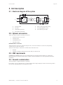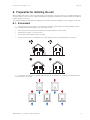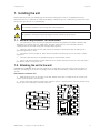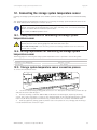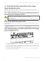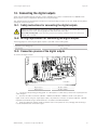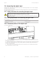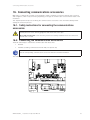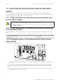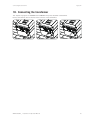
1
INGECON SUN STORAGE 1Play
Installation and Operation Manual
ABH2013IQE01_
02/2015
Ingeteam Power Technology, S.A. - Energy
Avda. Ciudad de la Innovación, 13
31621 SARRIGUREN (Navarra) - Spain
Tel.: +34 948 28 80 00
Fax.: +34 948 28 80 01
e-mail: [email protected]
Service Call Center: +34 948 698 715
Ingeteam
INGECON SUN STORAGE 1Play
Installation and Operation Manual
ABH2013IQE01_ - Installation and Operation Manual
iii
Ingeteam
The copy, distribution or use of this document or of its content requires written authorisation. Any breach thereof will be reported for
damages. All rights reserved including those of patent rights or design registration.
The conformity of the document content with the hardware described has been checked. However, discrepancies may exist. Liability
will not be assumed for total concordance. The information contained in this document is regularly reviewed and it is possible that
there may be changes in subsequent editions. Other functions may be available which are not covered by this document.
This document may be changed.
iv
ABH2013IQE01_ - Installation and Operation Manual
Contents
Ingeteam
Contents
Contents ......................................................................................................................................................5
1. About this manual.....................................................................................................................................8
1.1. Scope and nomenclature...................................................................................................................8
1.2. Recipients........................................................................................................................................8
1.3. Symbols...........................................................................................................................................8
2. Unit description........................................................................................................................................9
2.1. Electrical diagram of the system.........................................................................................................9
2.2. Optional accessories.........................................................................................................................9
2.3. EMC requirements............................................................................................................................9
2.4. Acoustic contamination.....................................................................................................................9
2.5. Specification table..........................................................................................................................10
2.6. Residual current device...................................................................................................................11
2.7. Description of cable inlets...............................................................................................................11
3. Safety....................................................................................................................................................12
3.1. Safety conditions............................................................................................................................12
3.2. Personal Protective Equipment (PPE)...............................................................................................14
4. Receipt of the unit and storage.................................................................................................................15
4.1. Reception......................................................................................................................................15
4.2. Equipment identification.................................................................................................................15
4.3. Transport damage...........................................................................................................................15
4.4. Storage..........................................................................................................................................15
4.5. Conservation..................................................................................................................................15
5. Equipment transport...............................................................................................................................16
5.1. Transport........................................................................................................................................16
5.2. Unpacking.....................................................................................................................................16
6. Preparation for installing the unit.............................................................................................................17
6.1. Environment...................................................................................................................................17
6.2. Environmental conditions................................................................................................................18
6.3. Supporting Surface and Fastening....................................................................................................18
6.4. Protection of the connection to the consumption grid ........................................................................20
6.5. Protection of the connection to the auxiliary grid/genset.....................................................................20
7. Installing the unit...................................................................................................................................21
7.1. General requirements for installation................................................................................................21
7.2. Attaching the unit to the wall...........................................................................................................21
7.3. Opening the housing.......................................................................................................................24
8. Connection of the storage system..............................................................................................................25
8.1. Safety instructions for connecting the storage system.........................................................................25
8.2. Wiring requirements for connecting the storage system.......................................................................25
8.3. Storage system connection process...................................................................................................25
9. Connecting the consumption grid.............................................................................................................26
9.1. Safety instructions for connecting to the consumption grid.................................................................26
9.2. Wiring requirements for connecting to the consumption grid...............................................................26
9.3. Consumption grid connection process...............................................................................................26
10. Auxiliary grid/genset connection.............................................................................................................27
10.1. Safety instructions for connecting the auxiliary grid/genset ..............................................................27
10.2. Wiring requirements for connecting the auxiliary grid/genset.............................................................27
10.3. Auxiliary grid/genset connection process ........................................................................................27
11. Connecting the PV array.........................................................................................................................28
11.1. Safety instructions for connecting the PV array ...............................................................................28
11.2. Wiring requirements for connecting the PV array..............................................................................28
11.3. PV array connection process ..........................................................................................................28
12. Connecting the storage system temperature sensor...................................................................................29
12.1. Safety instructions for connecting the storage system temperature sensor...........................................29
ABH2013IQE01_ - Installation and Operation Manual
5
Ingeteam
Contents
12.2. Wiring requirements for connecting the storage system temperature sensor........................................29
12.3. Storage system temperature sensor connection process....................................................................29
13. Connecting the CAN communication of the storage system management system.........................................30
13.1. Safety instructions for connecting the CAN communication of the storage system management system.30
13.2. Wiring requirements for connecting the CAN communication of the storage system management system...
30
13.3. Connection process of the CAN communication of the storage system management system..................30
14. Connecting the digital outputs................................................................................................................31
14.1. Safety instructions for connecting the digital outputs.......................................................................31
14.2. Wiring requirements for connecting the digital outputs.....................................................................31
14.3. Connection process of the digital outputs........................................................................................31
15. Connecting the digital input...................................................................................................................32
15.1. Safety instructions for connecting the digital input...........................................................................32
15.2. Wiring requirements for connecting the digital input........................................................................32
15.3. Connection process of the digital input...........................................................................................32
16. Connecting communications accessories.................................................................................................33
16.1. Safety instructions for connecting the communications accessories...................................................33
16.2. Connecting the communication accessories.....................................................................................33
17. Connecting the synchronisation input for three-phase systems...................................................................34
17.1. Safety instructions for connecting the synchronisation input for three-phase systems..........................34
17.2. Wiring requirements for connecting the synchronisation input for three-phase systems........................34
17.3. Connection process of the synchronisation input for three-phase systems...........................................34
18. Connecting the transformer....................................................................................................................35
19. Commissioning.....................................................................................................................................36
19.1. Equipment inspection...................................................................................................................36
19.1.1. Inspection............................................................................................................................36
19.1.2. Hermetic sealing of the unit..................................................................................................36
19.2. Start-up.......................................................................................................................................36
20. Display control......................................................................................................................................37
20.1. Keypad and LEDs.........................................................................................................................37
20.2. Display........................................................................................................................................38
20.3. Menu structure.............................................................................................................................39
20.4. Main menu...................................................................................................................................40
20.5. Start/Stop....................................................................................................................................40
20.6. Monitoring...................................................................................................................................40
20.7. Configuration................................................................................................................................42
20.7.1. Battery................................................................................................................................42
20.7.2. Inverter................................................................................................................................43
20.7.3. Grid/Genset..........................................................................................................................43
20.7.4. Operation Mode....................................................................................................................43
20.7.5. Digital I/O............................................................................................................................44
20.7.6. Change time/date.................................................................................................................45
20.7.7. Change Modbus Node...........................................................................................................45
20.7.8. PV grounding.......................................................................................................................45
20.7.9. Enter password.....................................................................................................................45
20.8. Language.....................................................................................................................................45
20.9. Further options.............................................................................................................................45
21. Shutting down the unit..........................................................................................................................47
21.1. Process of disconnecting the unit...................................................................................................47
22. Preventive maintenance.........................................................................................................................48
22.1. Safety conditions..........................................................................................................................48
22.2. Status of the housing....................................................................................................................48
22.3. Status of cables and terminals.......................................................................................................48
22.4. Cooling system.............................................................................................................................48
22.5. Environment.................................................................................................................................49
23. Troubleshooting....................................................................................................................................50
6
ABH2013IQE01_ - Installation and Operation Manual
Contents
Ingeteam
23.1. Alarms.........................................................................................................................................50
24. Waste handling.....................................................................................................................................52
ABH2013IQE01_ - Installation and Operation Manual
7
About this manual
Ingeteam
1. About this manual
The purpose of this manual is to describe the INGECON SUN STORAGE 1Play units and to provide appropriate
information for their correct reception, installation, start-up, maintenance and operation.
1.1. Scope and nomenclature
This manual is applicable to the following units:
Complete name
Abbreviation
Units without a transformer
INGECON SUN STORAGE 1Play 3TL
1Play 3TL
INGECON SUN STORAGE 1Play 6TL
1Play 6TL
Units with a transformer
INGECON SUN STORAGE 1Play 3
1Play 3
INGECON SUN STORAGE 1Play 6
1Play 6
This document will refer to the various models by both their complete name and their abbreviation. It will also
refer generically to any of the models from the INGECON SUN STORAGE 1Play family using the terms unit, inverter or
inverter/charger.
1.2. Recipients
This document is intended for qualified personnel.
The status of qualified personnel referred to in this manual will be, as a minimum, that which meets all the
standards, regulations and laws regarding safety applicable to the tasks of installing and operating this unit.
Ingeteam recommends this unit to be installed by a professional installer.
1.3. Symbols
This manual uses various symbols to emphasise and highlight certain texts. The general meanings are explained
below.
General warning.
General information.
Electrical danger.
Read the section indicated in this manual.
Hot surface.
Prohibition.
Explosion hazard.
8
ABH2013IQE01_ - Installation and Operation Manual
Unit description
Ingeteam
2. Unit description
2.1. Electrical diagram of the system
B
D
E
C
+
A
J56
J55 F
–
INGECON SUN STORAGE 1Play
G
A.
Storage system.
E.
Grid or auxiliary generator relay.
B.
PV input.
F.
Auxiliary grid/genset input.
C.
Transformer (optional).
G.
Consumption grid output.
D.
Consumption grid relay.
2.2. Optional accessories
These units may include the following accessories:
•
Communications accessories.
•
PV array inputs.
•
PV array DC switch.
•
AC power supply.
Communications accessories
There are distinct options for communicating the units. For more information consult the corresponding
communication accessories manual.
There are several ways to achieve this communication with these units:
•
RS-485.
•
Ethernet (including communication via RS-485, for optional use)
2.3. EMC requirements
INGECON SUN STORAGE 1Play units are equipped with the necessary filtering elements to comply with
EMC requirements for domestic applications in order to prevent disturbances in other equipment outside the
installation.
2.4. Acoustic contamination
The unit produces a slight buzz when in operation.
Do not place it in an occupied room, or on light supports which might amplify this buzz. The mounting surface
must be firm and appropriate for the weight of the unit.
ABH2013IQE01_ - Installation and Operation Manual
9
Unit description
Ingeteam
2.5. Specification table
3
3TL
6
6TL
Storage system voltage range (1)
48 ~ 300 V
48 ~ 300 V
96 ~ 300 V
96 ~ 300 V
Extended operating voltage (2)
48 ~ 420 V
48 ~ 420 V
96 ~ 420 V
96 ~ 420 V
Minimum operating voltage (1)
40 V
40 V
40 V
40 V
Maximum charge/discharge current
50 A
50 A
50 A
50 A
10 kWp
Storage system input (DC)
Battery type
Lead, Ni-Cd, Li-ion
PV array input (DC)
PV array maximum power
6.5 kWp
6.5 kWp
10 kWp
550 V
550 V
550 V
550 V
MPP voltage range
300 ~ 450 V
300 ~ 450 V
300 ~ 450 V
300 ~ 450 V
Operating voltage range (3)
Maximum input voltage
300 ~ 550 V
300 ~ 550 V
300 ~ 550 V
300 ~ 550 V
Minimum voltage for rated power
300 V
300 V
300 V
300 V
Maximum short circuit current
22 A
22 A
22 A
22 A
0 A rms
0 A rms
0 A rms
0 A rms
MPPT
1
1
1
1
Number of strings
2
2
2
2
Strings per MPP
2
2
2
2
20 A
20 A
30 A
30 A
Maximum inverter backfeed current to the array
Maximum input current
Auxiliary grid/genset input (AC)
Rated voltage
230 V
230 V
230 V
230 V
Voltage range
172 ~ 264 V
172 ~ 264 V
172 ~ 264 V
172 ~ 264 V
Nominal frequency
50 / 60 Hz
50 / 60 Hz
50 / 60 Hz
50 / 60 Hz
Frequency range
40 ~ 70 Hz
40 ~ 70 Hz
40 ~ 70 Hz
40 ~ 70 Hz
Load current range
0 ~ 13 A
0 ~ 13 A
0 ~ 26 A
0 ~ 26 A
Generator or grid maximum power
11,500 W
11,500 W
11,500 W
11,500 W
52 A
52 A
52 A
52 A
Nominal power (up to 40 ºC)
3 KVA
3 KVA
6 KVA
6 KVA
Maximum continuous power
3 kW
3 kW
6 kW
6 kW
Maximum transient current
Consumption grid output (AC)
Power (25°C) 30 min, 2 min, 3s (4)
3,500 / 3,900 / 5,080 W
6,400 / 6,900 / 7,900 W
Max. temperature for rated power
40 ºC
40 ºC
40 ºC
40 ºC
Maximum current
13 A
13 A
26 A
26 A
< 26 A rms (60 ms)
Maximum output fault current
Maximum output overcurrent protection
Rated voltage (5)
< 40 A rms (60 ms)
26 A rms
26 A rms
40 A rms
40 A rms
220 ~ 240 V
220 ~ 240 V
220 ~ 240 V
220 ~ 240 V
± 2%
± 2%
± 2%
± 2%
50 / 60 Hz
50 / 60 Hz
50 / 60 Hz
50 / 60 Hz
95.5 %
95.5 %
96 %
96 %
95 %
95.1 %
95.2 %
95.2 %
Air flow
45 m3/h
45 m3/h
45 m3/h
Weight
43.3 Kg
18.3 Kg
65 Kg
23.3 Kg
470 x 360 x 320 mm
470 x 360 x 180 mm
470 x 360 x 180 mm
470 x 360 x 320 mm
Voltage range
Nominal frequency (5)
Performance
Maximum efficiency
Euroefficiency
General data
Cooling system
Measurements (height x width x depth)
Stand-by current
Operating temperature
Relative humidity (without condensation)
Protection class
Contamination class
Markings
EMC and safety regulations
10
Forced ventilation
45 m3/h
< 10 W
< 10 W
< 10 W
< 10 W
–20 ~ +65 ºC
–20 ~ +65 ºC
–20 ~ +65 ºC
–20 ~ +65 ºC
0 ~ 95 %
0 ~ 95 %
0 ~ 95 %
0 ~ 95 %
IP65
IP65
IP65
IP65
2
2
2
2
CE
EN 61000-6-1, EN 61000-6-2, EN 61000-6-3, EN 61000-6-4, EN 61000-3-11, EN 610003-12, EN 62109-1, EN 62109-2, IEC62103, EN 50178, FCC Part 15, AS3100
ABH2013IQE01_ - Installation and Operation Manual
Unit description
Ingeteam
3
3TL
6
6TL
RD1699/2011, DIN V VDE V 0126-1-1, EN 50438, CEI 0-21, VDE-AR-N 4105:2011-08,
G59/2, G83/2(6), AS4777.2, AS4777.3, IEC 62116, IEC 61727, UNE 206007-1, ABNT
NBR 16149, ABNT NBR 16150, South African Grid code, IEEE 929Thailand MEA & PEA
requirements
Public grid connection regulations
The maximum power of the inverter is a calculation of the battery voltage multiplied by the maximum discharge current (50 A). (2) Only possible if there
is no PV energy. (3) Never exceed this value. Consider the voltage increase of the panels ‘Voc’ at low temperatures. (4) This power will be available if the
battery voltage multiplied by the maximum discharge current reaches said value. (5) This parameter can be set on the display. (6) For units of more than
16 A.
(1)
2.6. Residual current device
The units without a transformer (TL) incorporate a differential circuit breaker which serves to disconnect the unit in
the event of a 30mA differential current.
This residual current device exclusively protects the unit. A residual current device must be installed
to protect the installation according to the country’s legislation.
2.7. Description of cable inlets
Units without a transformer
D
E
F
A
G
B
F
I
H
J
A.
Storage system (PG20).
B.
PV array *.
C.
DC switch *.
D. Communications accessories
(PG20).
C
E. CAN communication of the
storage system management system
(PG16).
Units with a transformer
F.
D
E
F
G. Storage system temperature
sensor PT-100 (PG16).
A
G
B
F
H
Digital inputs / outputs (PG16).
I
J
K
C
H. Synchronisation input for threephase systems (PG16).
I.
Consumption grid (PG25).
J.
Auxiliary grid/genset (PG25).
K.
Transformer connection **.
* Optional.
** Units with a transformer.
K
ABH2013IQE01_ - Installation and Operation Manual
11
Safety
Ingeteam
3. Safety
This section describes the safety warnings and the Personal Protective Equipment used in the unit.
3.1. Safety conditions
General warnings
The operations described in the manual may be performed only by qualified personnel.
The status of qualified personnel referred to in this manual will be, as a minimum, that which meets
all the standards, regulations and laws regarding safety applicable to the tasks of installing and
operating this unit.
The responsibility for designating qualified personnel will always fall to the company to which the
personnel belong. It is necessary to decide which workers are suitable or not for carrying out specific
work to preserve their safety at the same time as complying with occupational safety legislation.
These companies are responsible for providing appropriate training in electrical equipment to their
personnel and for familiarising them with the contents of this manual.
All applicable safety-related legislation for electrical work must be complied with. Danger of electric
shock.
Compliance with the safety instructions set out in this manual or in the suggested legislation does
not imply exemption from other specific standards for the installation, place, country or other
circumstances that affect the inverter.
Opening the door of the housing does not imply there is no voltage inside.
There is a risk of electric shock even after disconnecting all power sources from the system.
Only qualified personnel may open it, following the instructions in this manual.
The entire manual must be read and understood in full prior to manipulating, installing or operating
the unit.
Following is a list of the basic obligatory safety standards for each country:
•
RD 614/2001 in Spain.
•
CEI 11-27 in Italy.
•
DIN VDE 0105-100 and DIN VDE 1000-10 in Germany.
•
UTE C18-510 in France.
Category III - 1000-Volt measuring instruments must be used for checking for the absence of voltage.
Ingeteam accepts no liability for any damages caused by improper use of its equipment.
Ingeteam accepts no liability for any damages caused by improper use of the equipment. Any work
carried out on any equipment which implies a modification of the original electrical arrangements
must be proposed in advance to Ingeteam. These must be studied and approved by Ingeteam.
12
ABH2013IQE01_ - Installation and Operation Manual
Safety
Ingeteam
Carry out all control and handling without voltage.
As a minimum security measure in this operation, you should always follow the so-called 5 golden
rules:
1.
Disconnect.
2.
Prevent any possible feedback.
3.
Check there is no voltage.
4.
Ground and short circuit.
5.
Protect from live elements, if any, and put up safety signs around the work zone.
Until these five steps are completed, the work area cannot be considered voltage-free and any work
performed will be considered to be work on live equipment.
The space for the installation of the storage system must be properly ventilated.
The storage system must be installed in such a way that any accidental short-circuits are avoidable.
Potential hazards for people
Bear in mind the following warnings concerning personal safety.
DANGER: Electric Shock.
The equipment may remain charged after disconnecting the renewable power supply and grid power.
Carefully follow the mandatory steps in the manual for removing the voltage.
DANGER: explosion.
There is a very low risk of explosion in very specific cases of malfunction.
The casing will protect people and property from the explosion only if it is correctly closed.
DANGER: Crushing and joint injuries.
Always follow the indications in the manual on moving and placing the unit.
The weight of this unit can cause injury if not handled correctly.
DANGER: High temperature.
The flow of outlet air can reach high temperatures which can cause injury to anybody exposed to it.
Potential hazards for the equipment
Bear in mind the following warnings concerning protection of the equipment.
CAUTION: Cooling.
The unit requires impurity-free air flow while it is operating.
Keeping the unit in the upright position and the inlets free of obstacles is essential for this air flow to
reach the inside.
CAUTION: connections.
After all duly authorised handling, check that the inverter is ready to start operation. Only after this
can you connect it following the instructions in the manual.
ABH2013IQE01_ - Installation and Operation Manual
13
Safety
Ingeteam
Do not touch boards or electronic components. The more sensitive components can be damaged or
destroyed by static electricity.
Do not disconnect or connect any of the terminals while the unit is operating. Disconnect and check
for absence of voltage first.
3.2. Personal Protective Equipment (PPE)
When working on the unit, use the following safety equipment recommended by Ingeteam as a minimum.
Name
Explanation
Safety footwear
In compliance with standard UNE-EN-ISO 20345:2012
Helmet
In compliance with standard EN 397:2012 + A1:2012
Helmet with face shield
In compliance with standard UNE-EN 166:2002, provided there are elements
with directly accessible voltage.
Safety goggles
In compliance with standard UNE-EN 166:2002
Working clothes
Close-fitting, non-flammable, 100% cotton
Dielectric gloves
In compliance with standard EN 60903:2005
Tools and / or equipment used in live work must have at least Category III-1000 Volts insulation.
Should the country’s regulations demand another kind of personal protection, the equipment recommended by
Ingeteam should be appropriately supplemented.
14
ABH2013IQE01_ - Installation and Operation Manual
Receipt of the unit and storage
Ingeteam
4. Receipt of the unit and storage
4.1. Reception
Keep the unit in its packaging until immediately before installation. Keep the unit in a horizontal position at all
times.
4.2. Equipment identification
The serial number of the equipment is its unique identifier. You must quote this number in any communication
with Ingeteam.
If you have purchased inverters with transformers, the transformer and inverter will be received in separate boxes.
It will be possible to identify which transformer corresponds to each unit by means of the serial number, shown on
the shipping label.
The unit’s serial number is also marked on the nameplate:
4.3. Transport damage
If the unit has been damaged during transport, proceed as follows:
1.
Do not proceed with the installation.
2.
Notify the distributor immediately within 5 days of receipt of the unit.
If ultimately the unit has to be returned to the manufacturer, the original packaging must be used.
4.4. Storage
Failure to follow the instructions provided in this section may lead to damage to the unit.
Ingeteam accepts no liability for damage resulting from the failure to follow these instructions.
If the unit is not installed immediately after reception, the following points should be taken into account in order to
avoid damage:
•
The package must be stored in the horizontal position.
•
Keep the unit free of dirt (dust, shavings, grease, etc.) and away from rodents.
•
Keep it away from water splashes, welding sparks, etc.
•
Cover the unit with a breathable protective material in order to prevent condensation due to ambient
humidity.
•
Units in storage must not be subjected to weather conditions other than those indicated in Section “2.5.
Specification table”.
•
It is very important to protect the unit from chemical products which can cause corrosion, as well as from
salty atmospheres.
•
Do not store the unit outdoors.
4.5. Conservation
In order to permit correct conservation of the units, you must not remove them from their original packaging until it
is time to install them.
In case of prolonged storage, the use of dry places avoiding, as far as possible, sharp changes in temperature is
recommended.
Deterioration of the packaging (tears, holes, etc.) prevents the units from being kept in optimum conditions before
installation. Ingeteam accepts no liability in the case of failing to observe this condition.
ABH2013IQE01_ - Installation and Operation Manual
15
Equipment transport
Ingeteam
5. Equipment transport
The unit must be protected, during transport, from mechanical knocks, vibrations, water splashes (rain) and any
other product or situation which may damage it or alter its behaviour. Failure to observe these instructions may
lead to loss of warranty on the product, for which Ingeteam is not responsible.
5.1. Transport
Transport using a pallet truck
At least the following requirements should be observed:
1.
Place the packaged units centred with respect to the forks.
2.
Try to locate them as close as possible to the part where the forks and the steering unit meet.
3.
In all cases, observe the instructions in the pallet truck’s user manual.
Transport using a forklift truck
At least the following requirements should be observed:
1.
Place the packaged units centred with respect to the forks.
2.
Try to locate them as close as possible to the part where the forks and the steering unit meet.
3.
Ensure that the forks are perfectly level to avoid overturning the unit.
4.
In any case, observe the instructions in the forklift truck's user manual.
Once the unit has been transported to the place where it is to be located and only when it is to be installed,
unpack the unit.
At this time, it can be transported vertically over a short distance without packaging. The guidelines in the next
point should be followed both for the unit and for the transformer.
Transport of the unpackaged unit
At least the following requirements should be observed:
1.
Use the two side holes to grasp the unit with both hands.
2.
Follow the necessary ergonomic advice for lifting weights.
3.
Do not release the unit until it is perfectly secured or placed.
4.
Ask someone else to guide the movements to be made.
5.2. Unpacking
Correct handling of the units is vitally important in order to:
•
Prevent damage to the packaging which enables them to be kept in optimum condition from shipping
until they are installed.
•
Avoid knocks and / or falls which may harm the mechanical characteristics of the units, e.g. cause
incorrect closure of doors, loss of protection rating, etc.
•
Avoid, as far as possible, vibrations which may cause subsequent malfunction.
If you observe any anomaly, please contact Ingeteam immediately.
Separating the packaging
You can deliver all the packaging to a non-hazardous waste management company.
In any event, each part of the packaging may be recycled as follows:
16
•
Plastic (polystyrene, bag and bubble wrap): the appropriate container.
•
Cardboard: the appropriate container.
ABH2013IQE01_ - Installation and Operation Manual
Preparation for installing the unit
Ingeteam
6. Preparation for installing the unit
When deciding the location of the unit and planning your installation, you must follow a set of guidelines based on
the specifications of the unit. This chapter summarises the guidelines and details the external elements needed for
correct operation of the unit.
This chapter summarises the guidelines and details the external elements needed for correct operation of the unit.
6.1. Environment
•
Place the units in a place which is accessible for installation and maintenance work and which permits
use of the keyboard and the reading of the front indicator LED.
•
Avoid corrosive environments that may affect the proper operation of the inverter.
•
Never place any object on top of the unit.
•
Do not expose the inverters to direct sunlight.
•
Do not install the units in inhabited rooms. The inverter produces a slight buzz when in operation.
•
If more than one inverter is installed, make sure the hot air extraction of one does not interfere with the
correct ventilation of another.
ABH2013IQE01_ - Installation and Operation Manual
17
Preparation for installing the unit
Ingeteam
•
Keep an area of 50 cm at the top and bottom of the unit and 30 cm at the side free of obstacles. Only in
this way will the unit’s cooling system operate correctly.
50 cm
30 cm
30 cm
30 cm
6.2. Environmental conditions
Environmental operating conditions indicated in section “2.7. Description of cable inlets” must be taken into
account when choosing the location of the unit.
The surrounding atmosphere must be clean and at temperatures above 40 ºC the relative humidity must be
between 4% and 50%. Higher percentages of relative humidity up to 95 % are tolerated at temperatures below 30
ºC.
It should be borne in mind that moderate condensation may occasionally occur as a consequence of temperature
variations. For this reason, apart from the unit's own protection, it is necessary to monitor these units once they
have been started up on sites where the conditions described above are not expected to be present.
In the event of condensation, never apply voltage to the unit.
6.3. Supporting Surface and Fastening
To guarantee good heat evacuation and promote sealing, the units must be placed on a perfectly vertical wall or,
failing this, with a slight slope of a maximum of +80° or -80°.
Reserve a solid wall to which to attach the unit. It must be possible to drill the wall and fit suitable wall anchors
and self-tapping screws to support the unit’s weight.
18
ABH2013IQE01_ - Installation and Operation Manual
Preparation for installing the unit
Ingeteam
For TL models, the distance between drilled holes will be as follows:
80
80
160
200
,5
Ø7
Ø
7,
5
324
Ø 7,5
In models with transformers, it is the transformer which will be secured to the wall. The inverter will subsequently
be fixed to the transformer.
100
100
257
Ø1
0
478,6
Drill the upper three holes before hanging the transformer and the lower three holes after hanging it, as explained
in Section “7.2. Attaching the unit to the wall”. See the measurements in the following figure.
ABH2013IQE01_ - Installation and Operation Manual
19
Preparation for installing the unit
Ingeteam
6.4. Protection of the connection to the consumption grid
Thermomagnetic circuit breaker
A thermomagnetic circuit breaker and / or fuse can be installed on the connection between the inverter and the
consumption grid.
The following table provides the necessary data for the selection of said device by the installer.
INGECON SUN STORAGE 1Play
Maximum inverter
current
Rated current for the
type B thermomagnetic
circuit breaker
3 / 3TL
13 A
20 A
6 / 6TL
26 A
32 A
You must take into account when selecting the protection that the ambient working temperature influences the
maximum current permitted by these protections as indicated by the manufacturer.
Residual current device
You must comply with applicable regulations governing the protection of people in the consumption grid.
6.5. Protection of the connection to the auxiliary grid/genset
A thermomagnetic circuit breaker and / or fuse can be installed on the connection between the inverter and the
auxiliary grid/genset.
The following table provides the necessary data for the selection of said device by the installer.
20
INGECON SUN STORAGE 1Play
Maximum auxiliary
grid/genset current
Rated current for the
type B thermomagnetic
circuit breaker
3 / 3TL
50 A
63 A
6 / 6TL
50 A
63 A
ABH2013IQE01_ - Installation and Operation Manual
Installing the unit
Ingeteam
7. Installing the unit
Before installing the unit, the packaging must be removed, taking special care not to damage the housing.
Check that there is no condensation inside the packaging. If there are signs of condensation, you must not install
the unit until you are sure it is completely dry.
All installation operations must comply with current regulations.
All operations involving moving heavy weights must be carried out by two people.
7.1. General requirements for installation
•
The environment of the unit must be appropriate and meet the guidelines described in Chapter “6.
Preparation for installing the unit”. Additionally, the parts used in the rest of the installation must be
compatible with the unit and comply with the applicable legislation.
•
Ventilation and the space for work, which must be suitable for maintenance tasks according to the
applicable regulations in force.
•
The external connection devices, which must be suitable and sufficiently close as set forth in current
regulations.
•
The feed cables must be of the appropriate gauge for the maximum current.
•
Special care must be taken to ensure that there are no external elements near the air inlets and outlets
that obstruct proper cooling of the unit.
7.2. Attaching the unit to the wall
INGECON SUN STORAGE 1Play units have a system for securing them to the wall using a plate. The steps for
fixing the unit properly are as follows. The weight of the unit and the transformer, if fitted, must be taken into
account.
Units without a transformer (TL)
1. Mark the fixing points for the plates on the wall and drill holes with a suitable bit for the screws to be
used to secure the plate to the wall later.
2. Fix the plate using stainless steel fittings to prevent corrosion. Suspend the unit from the plate by fitting
the two slats in the openings on the back of the unit.
ABH2013IQE01_ - Installation and Operation Manual
21
Installing the unit
Ingeteam
3. Mark the bottom fixing hole. Remove the inverter and drill the hole. Fit the inverter again and bolt the
bottom fixing.
4.
Check that the unit is properly secured.
Units with a transformer
1. Mark the fixing points for the plates on the wall and drill holes with a suitable bit for the screws to be
used to secure the plate to the wall later.
2.
Fix the plate using stainless steel fittings to prevent corrosion.
3. Suspend the transformer from the plate and make sure it fits properly. This operation must be carried out
by two people due to the weight of the transformer.
22
ABH2013IQE01_ - Installation and Operation Manual
Installing the unit
Ingeteam
4. Mark the bottom fixing point, remove the transformer and drill the bottom fixing hole. Fit the transformer
again and screw it in.
5.
Check that the transformer is well secured.
6. Suspend the inverter on the transformer by fitting the holes in the former onto the lugs at the top of the
transformer.
7.
Adjust the two housings to line up the two bottom fixings.
8.
Join the inverter and the transformer with the bolt, washers and nut provided.
9.
Check that the unit is properly secured.
ABH2013IQE01_ - Installation and Operation Manual
23
Ingeteam
Installing the unit
7.3. Opening the housing
Remove the 4 front bolts to open the housing cover. Make sure to disconnect the cable that joins the cover display
to the electronic card when taking of the cover (see figure).
The electronic card connector is shown as Display. Reconnect the connector wiring when the cover is put back in
to place.
24
ABH2013IQE01_ - Installation and Operation Manual
Connection of the storage system
Ingeteam
8. Connection of the storage system
This chapter explains the requirements and process for wiring the storage system to the unit. Read carefully before
starting the connection process.
8.1. Safety instructions for connecting the storage system
Before you start to make the connections, make sure there is no voltage in the inverter. Check that
the AC protection of the auxiliary grid/genset and the DC switch are open.
Do not switch on the power to the unit until you have successfully made the rest of the connections
and the unit is closed.
8.2. Wiring requirements for connecting the storage system
The wiring gauge for connecting the storage system is specified in the following table:
INGECON SUN STORAGE 1Play
Storage system wiring gauge
Cable diameter
10 ~ 16 mm2
7 ~ 13 mm
8.3. Storage system connection process
To connect the storage system:
1. Loosen the packing gland marked BATTERY + (see section “2.7. Description of cable inlets”), remove the
protective cap and pass the positive pole cable through it. Ingeteam recommends using a tubular terminal in
accordance with DIN 46 228/1.
2.
Open the clamp-type terminal J50 BATTERY +, insert the cable and close the terminal.
3. Loosen the packing gland marked BATTERY -, remove the protective cap and pass the positive pole cable
through it. Ingeteam recommends using a tubular terminal in accordance with DIN 46 228/1.
4.
Open the clamp-type terminal J51 BATTERY +, insert the cable and close the terminal.
5. Correctly tighten the packing glands to prevent losses to the protection class, verifying that the wiring is
not taut. Check that the connection is tight.
ABH2013IQE01_ - Installation and Operation Manual
25
Connecting the consumption grid
Ingeteam
9. Connecting the consumption grid
This chapter explains the requirements and process for wiring the consumption grid to the unit. Read carefully
before starting the connection process.
9.1. Safety instructions for connecting to the consumption grid
Before you start to make the connections, make sure there is no voltage in the inverter. Check that
the AC protection of the auxiliary grid/genset and the DC switch are open.
Do not switch on the power to the unit until you have successfully made the rest of the connections
and the unit is closed.
9.2. Wiring requirements for connecting to the consumption grid
The wiring gauge for connecting the consumption grid is specified in the following table:
INGECON SUN STORAGE 1Play
Consumption grid wiring gauge
4 ~ 16 mm2
Cable diameter
9 ~ 17 mm
9.3. Consumption grid connection process
To connect the consumption grid:
L
Live
N
Neutral
Ground
1. Loosen the packing gland marked LOADS (see section “2.7. Description of cable inlets”), remove the cap
and pass the consumption grid cable through it.
2. Open the clamp-type terminals J56 LOADS, insert the respective cables respecting the polarity and close
said terminals. Ingeteam recommends using a tubular terminal in accordance with DIN 46 228/1.
3. Correctly tighten the packing glands to prevent losses to the protection class, verifying that the wiring is
not taut. Check that the connection is tight.
The consumption grid neutral is not internally connected to ground.
26
ABH2013IQE01_ - Installation and Operation Manual
Auxiliary grid/genset connection
Ingeteam
10. Auxiliary grid/genset connection
This chapter explains the requirements and process for wiring the auxiliary grid/genset to the unit. Read carefully
before starting the connection process.
10.1. Safety instructions for connecting the auxiliary grid/genset
Before you start to make the connections, make sure there is no voltage in the inverter. Check that
the AC protection of the auxiliary grid/genset and the DC switch are open.
Do not switch on the power to the unit until you have successfully made the rest of the connections
and the unit is closed.
10.2. Wiring requirements for connecting the auxiliary grid/genset
The wiring gauge for connecting the auxiliary grid/genset is specified in the following table:
INGECON SUN STORAGE 1Play
Auxiliary grid/genset wiring gauge
6 ~ 16 mm2
Cable diameter
9 ~ 17 mm
10.3. Auxiliary grid/genset connection process
To connect the auxiliary grid/genset:
L
Live
N
Neutral
Ground
1. Loosen the packing gland marked GRID/GENSET (see section “2.7. Description of cable inlets”), remove
the cap and pass the consumption grid cable through it.
2. Open the clamp-type terminals J55 GRID/GENSET, insert the respective cables respecting the polarity
and close said terminals. Ingeteam recommends using a tubular terminal in accordance with DIN 46 228/1.
3. Correctly tighten the packing glands to prevent losses to the protection class, verifying that the wiring is
not taut. Check that the connection is tight.
ABH2013IQE01_ - Installation and Operation Manual
27
Connecting the PV array
Ingeteam
11. Connecting the PV array
Optionally, these units can be connected to a PV array.
This chapter explains the requirements and process for connecting the wiring from the PV array to the unit. Read
carefully before starting the connection process.
11.1. Safety instructions for connecting the PV array
Before you start to make the connections, make sure there is no voltage in the inverter. Check that
the AC protection of the auxiliary grid/genset and the DC switch are open.
Do not switch on the power to the unit until you have successfully made the rest of the connections
and the unit is closed.
11.2. Wiring requirements for connecting the PV array
The wiring gauge for connecting the PV array is specified in the following table:
INGECON SUN STORAGE 1Play
Recommended wiring gauge
4 mm2
11.3. PV array connection process
To connect the PV array:
28
1.
Make sure the PV array switch, if present, is off.
2.
Remove the caps from the quick connectors.
3.
Insert the connectors respecting the polarities indicated on the lower connections plate of the unit.
4.
so.
Ensure the connections are firm. If you wish to remove the aerial connectors, use the specific tool to do
ABH2013IQE01_ - Installation and Operation Manual
Connecting the storage system temperature sensor
Ingeteam
12. Connecting the storage system temperature sensor
Installing the storage system temperature sensor enables optimum charging to be carried out and extends battery
life.
This chapter explains the requirements and process for connecting the storage system temperature sensor to the
unit. Read carefully before starting the connection process.
Ingeteam recommends locating the sensor on a battery located in the central area of the storage
system. It should be placed approximately at the centre, vertically, of the cell selected, and suitably
fixed in accordance with the installation specifications.
Use a 3-wire PT-100 temperature sensor.
12.1. Safety instructions for connecting the storage system
temperature sensor
Before you start to make the connections, make sure there is no voltage in the inverter. Check that
the AC protection of the auxiliary grid/genset and the DC switch are open.
Do not switch on the power to the unit until you have successfully made the rest of the connections
and the unit is closed.
12.2. Wiring requirements for connecting the storage system
temperature sensor
The wiring gauge for connecting the storage system temperature sensor is specified in the following table:
INGECON SUN STORAGE 1Play
Temperature sensor wiring gauge
Cable diameter
0.25 mm2 ~ 1.5 mm2
4.5 ~ 10 mm
12.3. Storage system temperature sensor connection process
To connect the temperature sensor:
1. Loosen the corresponding packing gland (see Section “2.7. Description of cable inlets”), remove the cap
and pass the sensor cable through it.
2. Connect the wiring to terminal J60 PT-100, as indicated in the above figure, respecting the wiring
colours. The colours of the wires to connect to each terminal appear on the screen-printed electronic card (R:
red, R: red, W: white). Ingeteam recommends using a tubular terminal in accordance with DIN 46 228/1.
3. Correctly tighten the packing glands to prevent losses to the protection class, verifying that the wiring is
not taut. Check that the connection is tight.
ABH2013IQE01_ - Installation and Operation Manual
29
Connecting the CAN communication of the storage system management system
Ingeteam
13. Connecting the CAN communication of the storage
system management system
Installing the CAN communication enables the inverter to control the storage system management system.
This chapter explains the requirements and process for wiring the storage system CAN communication to the unit.
Read carefully before starting the connection process.
13.1. Safety instructions for connecting the CAN communication of
the storage system management system
Before you start to make the connections, make sure there is no voltage in the inverter. Check that
the AC protection of the auxiliary grid/genset and the DC switch are open.
Do not switch on the power to the unit until you have successfully made the rest of the connections
and the unit is closed.
13.2. Wiring requirements for connecting the CAN communication
of the storage system management system
The wiring gauge for connecting the CAN communication of the storage system management system is specified in
the following table:
INGECON SUN STORAGE 1Play
Temperature sensor wiring gauge
Cable diameter
0.25 mm2 ~ 1.5 mm2
4.5 ~ 10 mm
13.3. Connection process of the CAN communication of the storage
system management system
To connect the CAN communication:
1. Loosen the corresponding packing gland (see Section “2.7. Description of cable inlets”), remove the cap
and pass the cable through it.
2. Connect the wiring to terminal J18 CAN BATTERY as shown in the previous figure, respecting the printed
instructions on the screen-printed electronic card (H: high, L: low, GND: GND). Ingeteam recommends using a
tubular terminal in accordance with DIN 46 228/1.
3. Correctly tighten the packing glands to prevent losses to the protection class, verifying that the wiring is
not taut. Check that the connection is tight.
30
ABH2013IQE01_ - Installation and Operation Manual
Connecting the digital outputs
Ingeteam
14. Connecting the digital outputs
These units are provided with two volt-free contacts, whereby each contact is rated from 6 A to 250 VAC. Both
digital outputs can be configured for different uses using the display.
This chapter explains the requirements and process for wiring the digital outputs to the unit. Read carefully before
starting the connection process.
14.1. Safety instructions for connecting the digital outputs
Before you start to make the connections, make sure there is no voltage in the inverter. Check that
the AC protection of the auxiliary grid/genset and the DC switch are open.
Do not switch on the power to the unit until you have successfully made the rest of the connections
and the unit is closed.
14.2. Wiring requirements for connecting the digital outputs
The wiring gauge for connecting the digital outputs is specified in the following table:
INGECON SUN STORAGE 1Play
Temperature sensor wiring gauge
0.25 mm2 ~ 1.5 mm2
Cable diameter
4.5 ~ 10 mm
14.3. Connection process of the digital outputs
To connect the digital outputs:
Digital output 1
J36 EXT.1 RELAY
Digital output 2
J44 EXT.1 RELAY
1. Loosen the corresponding packing gland “2.7. Description of cable inlets”), remove the cap and pass the
cable through it.
2. Connect the cable to terminals J36 EXT. 1 RELAY and J44 EXT. 2 RELAY as shown in the previous
figure. In the case of using one single digital output, only make the connection to terminal J36 EXT. 1 RELAY.
Ingeteam recommends using a tubular terminal in accordance with DIN 46 228/1.
3. Correctly tighten the packing glands to prevent losses to the protection class, verifying that the wiring is
not taut. Check that the connection is tight.
ABH2013IQE01_ - Installation and Operation Manual
31
Connecting the digital input
Ingeteam
15. Connecting the digital input
The digital input is designed to operate with one dry contact or a DC voltage from 0 to 24 V. It can be configured
for different uses using the display.
This chapter explains the requirements and process for wiring the digital input to the unit. Read carefully before
starting the connection process.
15.1. Safety instructions for connecting the digital input
Before you start to make the connections, make sure there is no voltage in the inverter. Check that
the AC protection of the auxiliary grid/genset and the DC switch are open.
Do not switch on the power to the unit until you have successfully made the rest of the connections
and the unit is closed.
15.2. Wiring requirements for connecting the digital input
The wiring gauge for connecting the digital input is specified in the following table:
INGECON SUN STORAGE 1Play
Temperature sensor wiring gauge
Cable diameter
0.25 mm2 ~ 1.5 mm2
4.5 ~ 10 mm
15.3. Connection process of the digital input
To connect the digital input:
1. Loosen the corresponding packing gland (see Section “2.7. Description of cable inlets”), remove the cap
and pass the cable through it.
2. Connect the wiring to terminal J54 DIGITAL INPUT as shown in the previous figure, respecting the printed
polarities on the screen-printed electronic card (+, GND). Ingeteam recommends using a tubular terminal in
accordance with DIN 46 228/1.
3. Correctly tighten the packing glands to prevent losses to the protection class, verifying that the wiring is
not taut. Check that the connection is tight.
32
ABH2013IQE01_ - Installation and Operation Manual
Connecting communications accessories
Ingeteam
16. Connecting communications accessories
Optionally, a communication system can be installed in order to establish a connection with the unit to monitor
and configure it, either locally or remotely, depending on the type of communication chosen and the needs of the
installation.
This chapter explains the process for wiring the communications accessories to the unit. Read carefully before
starting the connection process.
16.1. Safety instructions for connecting the communications
accessories
Before you start to make the connections, make sure there is no voltage in the inverter. Check that
the AC protection of the auxiliary grid/genset and the DC switch are open.
Do not switch on the power to the unit until you have successfully made the rest of the connections
and the unit is closed.
16.2. Connecting the communication accessories
There are several ways to achieve this communication with these units:
•
RS-485.
•
Ethernet (including communication via RS-485, for optional use)
See the corresponding communications accessories manual for further information.
The communications accessories are connected to connectors J46A and J46B available on the electronic card.
ABH2013IQE01_ - Installation and Operation Manual
33
Connecting the synchronisation input for three-phase systems
Ingeteam
17. Connecting the synchronisation input for three-phase
systems
The synchronisation input enables the synchronisation of single-phase units to create a three-phase grid.
This chapter explains the requirements and process for wiring the synchronisation input for three-phase systems to
the unit. Read carefully before starting the connection process.
17.1. Safety instructions for connecting the synchronisation input
for three-phase systems
Before you start to make the connections, make sure there is no voltage in the inverter. Check that
the AC protection of the auxiliary grid/genset and the DC switch are open.
Do not switch on the power to the unit until you have successfully made the rest of the connections
and the unit is closed.
17.2. Wiring requirements for connecting the synchronisation input
for three-phase systems
The wiring gauge for connecting the synchronisation input for three-phase systems is specified in the following
table:
INGECON SUN STORAGE 1Play
Temperature sensor wiring gauge
Cable diameter
0.2 mm2 ~ 1.5 mm2
4.5 ~ 10 mm
17.3. Connection process of the synchronisation input for threephase systems
To connect the synchronisation input:
1. Loosen the corresponding packing gland “2.7. Description of cable inlets”), remove the cap and pass the
cable through it.
2. Connect the synchronism phase wiring to either of the two positions of terminal J61 PHASE SYNC as
shown in the previous figure. Ingeteam recommends using a tubular terminal in accordance with DIN 46
228/1.
3. Correctly tighten the packing glands to prevent losses to the protection class, verifying that the wiring is
not taut. Check that the connection is tight.
34
ABH2013IQE01_ - Installation and Operation Manual
Connecting the transformer
Ingeteam
18. Connecting the transformer
This chapter only applies to INGECON SUN STORAGE 1Play units fitted with a transformer.
Connect the external cable to the free aerial connector on the transformer.
ABH2013IQE01_ - Installation and Operation Manual
35
Commissioning
Ingeteam
19. Commissioning
This chapter details the process for the commissioning of the unit.
19.1. Equipment inspection
The correct condition of the installation must be checked before start-up.
Each installation is different, depending on its characteristics, the country in which it is located or other special
conditions which may apply. In all cases, before starting up, it is necessary to ensure that the installation complies
with the applicable legislation and regulations and that at least the part to be started up is complete.
19.1.1. Inspection
Before inverter start-up, a general inspection of the units must be carried out involving mainly:
Wiring check
•
Check that the cables are correctly connected to their connectors at the bottom of the housing.
•
Check that these cables are in a good condition and that there are no hazards in their environment which
damage them, such as sources of intense heat, objects which could cut them or arrangements which put them
at risk of impacts or pulls.
Check that the unit is properly secured
Check that the unit is secured firmly and is not at risk of falling.
19.1.2. Hermetic sealing of the unit
Ensure during installation operations that the unit’s level of sealing has not been altered during connection of the
unit.
Check the correct adjustment of the connectors and that any cable glands are well sealed.
Display cable
If the front cover has been opened at any time, ensure that the cable to the display remains firmly connected.
Cover
If the front cover has been opened at any time, attach it to the unit using its four bolts as follows:
1. Ensure that the cover is correctly aligned with the housing. This can be confirmed easily by checking that
the holes in the cover and the housing mate.
2. Lubricate the bolts. Whenever the unit is opened, it is mandatory to lubricate the bolts before putting
them back in to prevent them seizing.
3. Manually insert the four bolts into their threaded holes, starting at the top right, followed by the bottom
left and finally the other two.
4.
Tighten the bolts until a maximum torque of 5 Nm is applied to each with a calibrated tool.
5.
Check that the sealing is conserved.
The guarantee does not cover damage caused by inadequate sealing of the unit.
19.2. Start-up
Once a general visual inspection, wiring check and sealing check have been carried out, connect power to the unit.
The tasks outlined for this step must be carried out with the unit door always closed, thus avoiding possible
contact with live parts.
36
ABH2013IQE01_ - Installation and Operation Manual
Display control
Ingeteam
20. Display control
INGECON SUN STORAGE 1Play inverters/chargers incorporate a display and keypad unit to interface with the
installer or the user.
This interface allows the display of the main internal parameters and the configuration of the entire system during
installation.
Parameters, variables and commands are organised as menus and submenus.
20.1. Keypad and LEDs
The keypad has four keys:
To exit a parameter, leave a menu and returning to the next level up in the structure, to not
confirm a change or not accept a suggestion.
With this key you can scroll up the list of parameters or folders within the same level or increase
the value of an editable parameter by one base unit. To increase the value of a parameter by
intervals of 10 use the combination
+
. To increase the value of a parameter by intervals of
100 use the combination
+
.
Scroll down the list of parameters or folders within the same level or decrease the value of an
editable parameter by one base unit. To reduce the value of a parameter by intervals of 10
use the combination
+
. To reduce the value of a parameter by intervals of 100 use the
combination
+
.
Serves to accept a parameter as valid, to enter a lower level menu in the structure, to confirm a
change or accept a suggestion.
The front panel has three LEDs:
Green LED
•
Flashing for 1 second: inverter checking the storage system and starting up.
•
On: inverter generating voltage in the consumption grid or connected to the auxiliary
grid/genset.
Orange LED
•
Three flashes: the external fan is not working correctly.
•
Flashing every 1 second: the internal fan is not running correctly.
•
Flashing every 3 seconds: inverter limiting power due to high temperature.
•
On: presence of alarm.
Red LED
•
On: manual shutdown.
ABH2013IQE01_ - Installation and Operation Manual
37
Display control
Ingeteam
20.2. Display
The following figure shows the main screen of the inverter and the meaning of each field.
a
10:23
b
c
23/01/2015
e
f
g
d
h
a.
Current time, hh:mm.
b.
Current date, dd/mm/yy.
c. Storage system data. The voltage in volts,
current in amps and charge status is shown
alternately. If COM is shown in place of these
values, there is no communication with the storage
system manager.
d. PV array data. The voltage in volts and current
in amps of the PV array is shown alternately.
e. Current power percentage. The letter indicates
the reason for the power limitation. (1)
i
f. Consumption grid output data. The power in
Watts and the voltage in volts is shown alternately.
g. Auxiliary grid/genset input data. The power in
Watts and the voltage in volts of the auxiliary grid/
genset is shown alternately.
h. Phase of the three-phase system. In the
event that the inverter is operating in a three-phase
system the phase in which it is operating will be
indicated (R, S or T).
i.
This indicates that the system is operating
to the interface setting. If the symbol flashes, this
means that communications have been lost. As a
result, the display will switch to standby.
In the event that the inverter is connected to a grid or auxiliary generator the current power percentage and the
most restrictive reason for power limitation are shown. The various reasons for limiting the power are explained
subsequently:
(1)
38
M
Limitation due to user settings.
B
Limitation due to the storage system charge status.
T
Limitation due to high temperature in the unit.
D
Auxiliary grid/genset input availability.
C
Limitation due to external communication.
ABH2013IQE01_ - Installation and Operation Manual
Display control
Ingeteam
20.3. Menu structure
Start screen
Main menu
Start/Stop
Switch to start
Switch to stop
Monitoring
Battery
BMS(1)
PV
Inverter
Grid
I/O
Alarm
Fw
Data
Configuration
Battery
Lead-Acid
Lithium
Inverter
RMS Voltage
Frequency
AC Phase.
Grid/Genset
Type of grid
Generator
Grid
Manual connection
Scheduling
Operation Mode
Stand-Alone
Grid support
Backup
Self-consumption
Digital I/O
Digital output 1
Digital output 2
Digital Input 1
Change time/date
Change Modbus Node
PV grounding
Enter password
Language
Further options
Emergency charge
Partial data reset
Manual equalization
Start/Stop Battery
Send CAN Commands
Fan test
ABH2013IQE01_ - Installation and Operation Manual
39
Display control
Ingeteam
20.4. Main menu
10:23
23/01/2015
The main menu contains the following submenus:
Start/Stop
Start-up and manual stopping of the inverter.
Monitoring
Displays the main variables that indicate the operating status of the unit.
Configuration
Modify parameters to adapt the unit to different operational conditions.
Language
Select the display language.
Further options
Shows further available options.
To access the various menus and submenus, the desired option
and
must be highlighted over a black background using the
keys and press the
key to access it.
10:23
23/01/2015
Configuration
20.5. Start/Stop
The operation of the inverter can be stopped and started manually using this option.
The Start or Stop status remains unchanged even if the unit becomes switched off.
20.6. Monitoring
You may want to find out certain parameters of the unit. This facilitates the monitoring of the unit.
To consult the monitoring access Main menu > Monitoring. A series of screens enable you to consult the
parameters in the following groups:
Battery
Battery manager
Photovoltaic
Inverter
Grid
Digital I/O
Alarm
FirmWare
Data
Battery monit.
Parameter
VBAT
40
Explanation
Storage system voltage (V).
ABH2013IQE01_ - Installation and Operation Manual
Display control
Ingeteam
Parameter
IBAT
Explanation
Storage system current (A). Positive for discharge, negative for charge.
SOC
Estimation of the storage system charge status (%).
Status
Status of the storage system. The following states may be shown: Stop, Discharge, Charge,
Absorption, Flotation or Equalization.
Tempbat
Storage system temperature (ºC).
Bat. manager monit.
Parameter
Explanation
VBAT
Storage system voltage (V).
IBAT
Storage system current (A). Negative for discharge, positive for charge.
SOC
Estimation of the storage system charge status (%).
I MAx Ch
Maximum charge current permitted by the storage system manager.
I MAx Dch
Maximum discharge current permitted by the storage system manager.
Photovoltaic monit.
Parameter
Explanation
Vdc
Photovoltaic input voltage (V).
Idc
Photovoltaic input current (A).
Inverter monit.
Parameter
Explanation
Vac
Voltage generated by the inverter (V).
Iac
Current through the inverter (A).
Fac
Frequency generated by the inverter (Hz).
Sac
Apparent power (VA) through the inverter.
PhiCos
Cosine of Phi. Cosine of the phase shift angle between the voltage and current supplied by
the inverter. The cosine of phi can be positive or negative.
•
Positive: the inverter injects positive reactive energy. The current is ahead with
respect to the voltage.
•
Negative: the inverter injects negative reactive energy. The current is delayed with
respect to the voltage.
Grid monit.
Parameter
Explanation
Vac
Auxiliary grid/genset voltage (V).
Iac
Auxiliary grid/genset current (A).
Fac
Auxiliary grid/genset frequency (Hz).
SAC
Auxiliary grid/genset apparent power (VA).
Status
Indicates whether the inverter is connected to or disconnected from the auxiliary grid/
genset.
Digital I/O monit.
Parameter
Output 1
Explanation
Indicates the configuration of the digital output 1.
Output 2
Indicates the configuration of the digital output 2.
Input 1
Indicates the configuration of the digital input 1.
ABH2013IQE01_ - Installation and Operation Manual
41
Display control
Ingeteam
Alarm monit.
Parameter
Explanation
Alarm
Status of inverter alarms.
Code1
Unit operating code. This can be requested from Ingeteam’s customer services.
Code2
Unit operating code. This can be requested from Ingeteam’s customer services.
Firmware monit.
Parameter
Explanation
FW Ver.
Unit firmware version.
DFW Ver.
Unit display firmware version.
D. Boot
Internal program version.
Sun Fw
Unit firmware revision.
Sun d.
Display firmware revision.
Data monit.
Parameter
Explanation
S/N
Unit serial number.
Comm. Node
Number assigned to the inverter to identify it in a Modbus grid.
RAD. temp.
Unit radiator temperature.
CI temp.
Unit internal temperature.
PT-100 temp.
PT-100 temperature sensor.
20.7. Configuration
With the exception of the modification of date and time, the other configurations must be carried out
by the unit installer and never the user.
The installer must have sufficient knowledge to be able carry out the installation correctly.
Ingeteam accepts no liability for incorrect use of the installer password nor the consequences that
may arise from incorrect configuration of the unit by the user and / or the installer.
In order to modify the Configuration menu parameters, the key 0332 must first be entered into
the Configuration > Enter password submenu.
When the password is entered correctly, an asterisk will appear at the top of the Configuration
menu.
20.7.1. Battery
This menu is for selecting the type of batteries to be used in the installation and configuring their parameters.
The > symbol points to the option selected.
To choose a different option to the one currently selected and configure it, highlight it using the
press
.
or
keys and
If the option selected is Lead-Acid the following parameters must be set:
Parameter
Explanation
Vnominal
Storage system rated voltage (V).
Capacity
Storage system (C20) capacity, in Ah.
I Charge
Maximum storage system charge current, in amps.
I Discharge
Maximum storage system discharge current, in amps.
42
ABH2013IQE01_ - Installation and Operation Manual
Display control
Ingeteam
Parameter
Explanation
Comp. Temp.
Storage system voltage compensation constant as a function of temperature (V/ºC).
V Absorption
Storage system absorption voltage (V).
V Flotation
Storage system flotation voltage (V).
V Equalization
Storage system equalization voltage (V).
T absorption
Duration of absorption charge, in minutes. Time for which the storage system must be
maintained at the absorption voltage.
T Equalization
Duration of equalization charge, in minutes. Time for which the storage system must be
maintained at the equalization voltage.
N.EQU. Cycles
Number of cycles to carry out an automatic equalization.
20.7.2. Inverter
From this menu the parameters of the inverter/charger can be set.
Parameter
Explanation
RMS Voltage
RMS voltage generated (V).
Frequency
Frequency of generated voltage (Hz).
AC Phase
Phase (R, S, T or single phase) to be generated by the inverter. The single phase will be
configured by default.
20.7.3. Grid/Genset
Type of grid
This menu is for selecting and configuring the type of auxiliary grid/genset input to be used in the installation.
The > symbol points to the option selected. To select the desired option and configure it, press
once it is highlighted.
on the option
If the option selected is Generator, the following parameters must be set:
Parameter
Explanation
Rat. Power
Auxiliary generator rated power, in watts. Obtain this information from the generator
manufacturer.
Vac MIN
Minimum AC voltage of the generator, in volts. Obtain this information from the generator
manufacturer.
Vac MAX
Maximum AC voltage of the generator, in volts. Obtain this information from the generator
manufacturer.
Fac MIN
Minimum AC frequency of the generator (Hz).
Fac MAX
Maximum AC frequency of the generator (Hz).
If the option selected is Grid, the country in which the unit is installed must be set.
By default the voltage and frequency values are set in accordance with the standards in the selected country.
Should these values be modified, Ingeteam accepts no liability for any consequences which may occur as a result
of this modification.
Manual connection
Allows the inverter to be manually connected to the auxiliary grid/genset immediately. The unit will continue to run
until the shut-down is ordered by the same method.
Scheduling
Allows the inverter to be manually connected to the auxiliary grid/genset in accordance with the scheduling
established.
20.7.4. Operation Mode
This menu is for selecting the strategy to be used in the installation and configuring its parameters.
ABH2013IQE01_ - Installation and Operation Manual
43
Display control
Ingeteam
The > symbol points to the option selected. To select the desired option and configure it, press
once it is highlighted.
on the option
Stand-Alone
The inverter generates an alternative stand-alone grid and acts as a grid manager, guaranteeing the balance
between generation, consumption and the storage system. In order to do this, it controls the energy flow between
the grid and the batteries in accordance with the situation at all times. It enables a solar energy source to be
integrated into the grid using INGECON SUN inverters. The control system manages the power produced by the
photovoltaic inverters, based on the consumption data and the battery charge status. The auxiliary generation
source (a generator or the public grid) only connects when the battery charge status is below a specific,
programmable level.
Self-consumption
This operating mode is intended for grid connection systems with renewable energy sources, in order to minimise
consumption from the grid. If energy production is greater than demand, the excess can be used to charge the
batteries or to inject into the grid if the batteries are completely charged.
If the loads require more energy than that produced by the renewable sources, the batteries will be in charge of
satisfying this demand, increasing the self-consumption ratio.
Grid support
In conjunction with INGECON EMS Manager, the INGECON SUN STORAGE 1Play inverter can adapt the output
power of the PV plant to a pre-set value, enabling a constant power value to be achieved or the power variation
ramp to be controlled.
UPS (backup)
This operating mode was designed for systems connected to the grid, where grid outages are long and frequent,
and an auxiliary energy source is necessary. The INGECON SUN STORAGE 1Play inverter operates connected to
the alternative grid. In order to guarantee an energy source, the inverter keeps the batteries charged. During a grid
outage the battery inverter generates the AC grid and the energy stored in the batteries is used to supply the loads.
If there are sources of renewable energy connected to the grid and the energy generated is greater than the
demand, the excess can be injected into the grid.
For all the previously mentioned modes the following parameters must be set:
Parameter
Explanation
SOCMAX
Maximum charge limit of renewable sources. In Stand-Alone mode the auxiliary grid/genset
input is deactivated.
SOCRED
Maximum charge limit from the auxiliary grid/genset input.
SOCMIN
Minimum limit for switching to standby. In Stand-Alone mode the auxiliary grid/genset
input is activated.
SOCRECX
Value at which, once passed, the unit starts generation in the consumption grid, as long as
the SOCDESCX (SOCRECX ≤ SOCMIN). has been previously reached.
SOCDESCX
Minimum limit for switching to the shutdown status (SOCDESCX ≤ SOCRECX).
Charging
Power
Maximum battery charging power, in Watts.
Grid Power
Grid Power, in Watts. It can be positive or negative:
•
Positive: maximum power injected into the grid.
•
Negative: minimum power consumed from the grid.
20.7.5. Digital I/O
In this menu the digital inputs and outputs are configured.
The configuration options for the digital outputs are:
Option
No Configuration
44
Explanation
No configuration.
ABH2013IQE01_ - Installation and Operation Manual
Display control
Ingeteam
Option
Explanation
Generator
Auxiliary generator activation signal.
Low Bat. Voltage
Storage system voltage below parameter set.
High Bat. Voltage
Storage system voltage above parameter set.
Non-Critical Loads
Connection / disconnection of non-crit. loads when there is no grid or auxiliary
generator.
Neutral Ground
Connection / disconnection of inverter neutral ground.
AC Grid Contactor
Opening / closing of an external AC contactor for connecting an inverter to the grid
or auxiliary generator.
Wake-Up Battery
Storage system manager activation signal.
ON/OFF by Comm.
Manual opening / closing via communications.
The digital input options are:
Option
Explanation
No Configuration
No configuration.
Start/Stop
Start/Stop the inverter.
Contactor AC
External AC contactor status reading.
20.7.6. Change time/date
Change the current time and date.
20.7.7. Change Modbus Node
Change the unit's Modbus node number.
20.7.8. PV grounding
Configure the type of PV grounding used in the installation. The grounding is only possible in units with a
transformer.
20.7.9. Enter password
An installer password must be introduced in order to make changes in the unit’s configuration. The password is
0332.
This password is reserved for installers and not end users. Ingeteam accepts no liability for incorrect
use of this password.
20.8. Language
Select the language in which you wish to view the display menus.
20.9. Further options
Emergency charge
Switch on the inverter for a brief period of time to charge the storage system.
Partial data reset
This allows the partial energy meters, partial connection time and number of partial connections to be reset.
Manual equalization
This enables a manual equalization of the storage system to be carried out.
Start/Stop battery
Start or stop the storage system manager. The > symbol points to the option selected. To select the desired option
and configure it, press
on the option once it is highlighted.
ABH2013IQE01_ - Installation and Operation Manual
45
Display control
Ingeteam
The unit will be ready to work with the storage system manager if the Start option has been configured.
Send CAN Commands
Send commands to the storage system manager via the CAN communication.
Test Fans
Test the unit's fans. The test will last approximately 15 seconds. After this time, the test will automatically
deactivate.
46
ABH2013IQE01_ - Installation and Operation Manual
Shutting down the unit
Ingeteam
21. Shutting down the unit
This section describes the procedure to shut down the unit.
If you wish to work inside the unit, these instructions must be carried out in the order shown here to
remove the power.
21.1. Process of disconnecting the unit
1.
Manually stop the inverter, using the Start/Stop option in the display menu.
2.
Remove both the direct voltage (Vdc) and the alternating voltage (Vac) arriving at the unit.
3. Wait 10 minutes for the existing capacities to discharge, the hot parts -which may cause burns- to cool
and the fan blades to stop turning.
4.
Check there is no voltage.
5. Signal cut-off point (Vac and Vdc) with a sign reading ¨Caution no switching…¨. If necessary, rope off the
work area.
ABH2013IQE01_ - Installation and Operation Manual
47
Preventive maintenance
Ingeteam
22. Preventive maintenance
The recommended preventive maintenance tasks must be carried out at least ANNUALLY, except where otherwise
stated.
22.1. Safety conditions
Before opening the unit, you must remove the power (see Section “21. Shutting down the unit”).
You must consider the set of conditions listed below as minimum requirements.
An open housing never implies an absence of voltage in the unit, so only qualified personnel may
access the unit, following the safe operation guidelines stipulated in this document.
Ingeteam accepts no liability for any damages caused by improper use of the equipment. Any work
carried out on any equipment which implies a modification of the original electrical arrangements
must be proposed in advance to Ingeteam. These must be studied and approved by Ingeteam.
All the maintenance checks included here must be carried out with the machine stopped, under safe
conditions for handling, including those specified by the client for these types of operation.
When carrying out maintenance work on the unit, the Personal Protective Equipment specified in
Section “3.2. Personal Protective Equipment (PPE)” of this document must be worn.
After completing the maintenance task, replace the front cover and secure it with the bolts supplied.
22.2. Status of the housing
A visual check of the condition of the housing must be carried out, confirming the condition of the seals and the
cover, as well as the fixing of the units to their anchor points, both at the wall and on the transformer if these exist.
In addition, you must check the condition of the housing for dents or scratches that might degrade the housing or
cause it to lose its protection classification. If you notice these types of defect, the affected parts must be repaired
or replaced.
Check that there is no moisture inside the housing. If moisture exists, you must dry it before making electrical
connections.
Check the correct fixing of the housing components to their corresponding anchoring points.
22.3. Status of cables and terminals
•
Check the correct path of the cables so they do not come into contact with live parts.
•
Check the insulation deficiencies and hot spots by checking the colour of the insulation and terminals.
•
Check that the connections are properly adjusted.
22.4. Cooling system
48
•
Checking the status of exhaust fans, cleaning and replacing them if necessary.
•
Clean the radiator fins and the cooling grids.
ABH2013IQE01_ - Installation and Operation Manual
Preventive maintenance
Ingeteam
22.5. Environment
Check the environment to avoid amplifying or transmitting the buzz.
ABH2013IQE01_ - Installation and Operation Manual
49
Troubleshooting
Ingeteam
23. Troubleshooting
This is a guide for troubleshooting problems that may arise in the installation and operation of INGECON SUN
STORAGE 1Play units.
Troubleshooting for the INGECON SUN STORAGE 1Play inverter must be performed by qualified
personnel in compliance with the general safety instructions in this manual.
23.1. Alarms
In the event that more than one alarm is generated at the same time, the hexadecimal codes
corresponding to each alarm are added together. That is to say, if alarm 0006H is displayed, alarms
0002H and 0004H are being produced simultaneously.
Alarm
Code
Description
Code 2: 0x0080H
The storage system has reached
the minimum configured voltage
or the minimum configured charge
status.
Code 2: 0x0100H
The storage system has reached
the maximum voltage.
Code 2: 0x0040H
Auxiliary grid/genset input
frequency out of range.
Code 2: 0x0040H
Auxiliary grid/genset input voltage
out of range.
Code 1: 0x0004H
Insulation fault. Insulation
resistance out of range.
Check, on the display, that the PV array grounding is
correctly configured.
Residual current out of range.
Check that there are no insulation faults in the PV
array and in the storage system.
0001H
0002H
0004H
0020H
Code 1: 0x0400H
Code 1: 0x0800H
0080H
Code 2: 0x0002H
Code 2: 0x0001H
Inspect the storage system configuration (see section
“20.7.1. Battery” and “20.7.4. Operation Mode”).
If the configuration is correct, start the system by
performing an emergency charge (see section “20.9.
Further options”).
Inspect the storage system configuration (see section
“20.7.1. Battery”).
Check the auxiliary grid/genset input connections.
Check that the frequency is within range.
Check the configuration (see Section “20.7.3. Grid/
Genset”)
Check the auxiliary grid/genset input connections.
Check that the voltage is within range.
Check the configuration (see Section “20.7.3. Grid/
Genset”)
If the error persists, contact the Technical Service.
Code 1: 0x1000H
0040H
Solution
Fault in the synchronisation signal
for three-phase systems.
Temperature out of operating range
Check the connections of the synchronisation input for
three-phase systems.
Inspect the AC Phase configuration.
This may be normal if the room temperature exceeds
the maximum of the unit. Check the fan operation
by performing the test (see section “20.9. Further
options”).
Protect the inverter from direct exposure to sunlight.
Cool the room where the inverter is installed.
0200H
-
0400H
Code 1: 0x2000H
50
Inverter setting change
Normal shut down due to a change in the inverter
setting.
Manual shutdown. The inverter has
been manually stopped.
Start the inverter by means of the display or
communications.
ABH2013IQE01_ - Installation and Operation Manual
Troubleshooting
Alarm
Ingeteam
Code
Description
Code 1: 0x0020H
Hardware fault in the DC/DC phase.
Code 1: 0x0040H
HW fault in the DC/AC conversion
phase.
Code 1: 0x0080H
Hardware fault in the VAC sensor.
Code 1: 0x0100H
Hardware fault in the residual
current sensor.
10000H
-
Inverter overload. The inverter
is supplying more power than
its maximum power in the
consumption grid.
Check the installation consumptions.
20000H
-
Short circuit in the consumption
grid output.
Check the consumption grid installation.
0800H
80000H
Code 2: 0x0200H
Error communicating with the
storage system manager.
ABH2013IQE01_ - Installation and Operation Manual
Solution
Check the installation in the DC and AC part.
Disconnect the DC and AC inverter. Wait until the LEDs
go off and re-connect.
If the error persists, contact the Technical Service.
Check the CAN communication wiring of the storage
system management system.
Make sure that the storage system starts via the
display (see section “20.9. Further options”).
51
Waste handling
Ingeteam
24. Waste handling
These units use components that are harmful to the environment (electronic cards, batteries or cells, etc.).
At the end of the unit's life, the waste must be correctly processed by an authorised hazardous
waste management company.
Ingeteam, in accordance with its policy of respect for the environment, will inform the
authorised manager, via this Section, of the location of components to be decontaminated.
At the end of the unit's life, the waste must be processed by an authorised waste management company.
Ingeteam, in accordance with its policy of respect for the environment, will inform the authorised manager, via this
Section, of the location of components to be decontaminated.
The elements within the unit that must be handled individually are:
1.
Electrolytic capacitors or capacitors containing PCB.
2.
Batteries or accumulators
3.
Printed circuit boards
4.
Liquid crystal displays.
Their location is shown in the following illustrations.
1
2
3
52
4
ABH2013IQE01_ - Installation and Operation Manual
Notes
Notes
Europe
America
Asia
Ingeteam Power Technology, S.A.
Energy
Avda. Ciudad de la Innovación, 13
31621 SARRIGUREN (Navarra) - Spain
Tel: +34 948 28 80 00
Fax: +34 948 28 80 01
email: [email protected]
Ingeteam INC.
5201 Great American Parkway, Suite 320
SANTA CLARA, CA 95054 - USA
Tel: +1 (415) 450 1869
+1 (415) 450 1870
Fax: +1 (408) 824 1327
email: [email protected]
Ingeteam Shanghai, Co. Ltd.
Shanghai Trade Square, 1105
188 Si Ping Road
200086 SHANGHAI - P.R. China
Tel: +86 21 65 07 76 36
Fax: +86 21 65 07 76 38
email: [email protected]
Ingeteam GmbH
Herzog-Heinrich-Str. 10
80336 MÜNCHEN - Germany
Tel: +49 89 99 65 38 0
Fax: +49 89 99 65 38 99
email: [email protected]
Ingeteam INC.
3550 W. Canal St.
Milwaukee, WI 53208 - USA
Tel: +1 (414) 934 4100
Fax: +1 (414) 342 0736
email: [email protected]
Ingeteam SAS
Le Naurouze B - 140 Rue Carmin
31676 Toulouse Labège cedex - France
Tel: +33 (0)5 61 25 00 00
Fax: +33 (0)5 61 25 00 11
email: [email protected]
Ingeteam, S.A. de C.V.
Ave. Revolución, nº 643, Local 9
Colonia Jardín Español - MONTERREY
64820 - NUEVO LEÓN - México
Tel: +52 81 8311 4858
Fax: +52 81 8311 4859
email: [email protected]
Ingeteam Power Technology India Pvt. Ltd.
2nd floor, 431
Udyog Vihar, Phase III
122016 Gurgaon (Haryana) - India
Tel: +91 124 420 6491-5
Fax: +91 124 420 6493
email: [email protected]
Ingeteam S.r.l.
Via Emilia Ponente, 232
48014 CASTEL BOLOGNESE (RA) - Italy
Tel: +39 0546 651 490
Fax: +39 054 665 5391
email: [email protected]
Ingeteam, a.s.
Technologická 371/1
70800 OSTRAVA - PUSTKOVEC
Czech Republic
Tel: +420 59 732 6800
Fax: +420 59 732 6899
email: [email protected]
Ingeteam Sp. z o.o.
Ul. Koszykowa 60/62 m 39
00-673 Warszawa - Poland
Tel: +48 22 821 9930
Fax: +48 22 821 9931
email: [email protected]
Ingeteam Ltda.
Estrada Duílio Beltramini, 6975
Chácara Sao Bento
13278-074 VALINHOS SP - Brazil
Tel: +55 19 3037 3773
Fax: +55 19 3037 3774
email: [email protected]
Ingeteam SpA
Bandera , 883 Piso 211
8340743 Santiago de Chile - Chile
Tel: +56 2 738 01 44
email: [email protected]
Africa
Ingeteam Pty Ltd.
Unit 2 Alphen Square South
16th Road, Randjiespark,
Midrand 1682 - South Africa
Tel: +2711 314 3190
Fax: +2711 314 2420
email: [email protected]
Australia
Ingeteam Australia Pty Ltd.
Suite 112, Level 1, Mike Codd Building 232
Innovation Campus, Squires Way
NORTH WOLLONGONG, NSW 2500 - Australia
email: [email protected]
ABH2013IQE01_
02/2015
Ingeteam Power Technology, S.A.
www.ingeteam.com