1
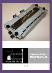
CHASSIS2 PRO
USER MANUAL
Issue 2a
CHASSIS2 PRO
USER MANUAL
www.avonsideworks.com
[email protected]
Contents
Contents ........................................................................................................................................... 2
Scope ................................................................................................................................................ 2
Packing List ....................................................................................................................................... 3
Product Description .......................................................................................................................... 3
Specification ..................................................................................................................................... 4
Parts Identification ........................................................................................................................... 6
Instructions for Use ........................................................................................................................ 13
Cleaning & Maintenance ................................................................................................................ 16
Further Information........................................................................................................................ 17
Manufacturer Information ............................................................................................................. 17
Scope
This manual covers both CHASSIS2 PRO and CHASSIS2 SUPERPRO. Differences are highlighted in
the text. All photographs are of the CHASSIS2 PRO the design of the CHASSIS2 SUPERPRO is exactly
the same but each side of the centreline of the jig is 75mm longer.
Page 2
CHASSIS2 PRO
USER MANUAL
www.avonsideworks.com
[email protected]
Packing List
Your CHASSIS2 PRO is housed in a robust plastic storage case containing:
CHASSIS2 PRO jig, ready assembled, with the Vertical Fence fitted upside down
5 off 1/8” Short Pins
5 off 1/8” Long Pins
5 off 2mm Long Pins
5 off 1mm to 1.5mm bushes
1 off End Fence with thumb nut
4 off Clamps with thumb screws
1 off 2.5mm Allen Key
1 bag of Silica Gel
Instruction CD
Your CHASSIS2 SUPERPRO is housed in a robust plastic storage case containing:
CHASSIS2 PRO jig, ready assembled, with the Vertical Fence fitted upside down
5 off 3/16”” Short Pins
5 off 3/16” Long Pins
1 off End Fence with thumb nut
4 off Clamps with thumb screws
1 off 2.5mm Allen Key
1 bag of Silica Gel
Instruction CD
Product Description
The CHASSIS2 PRO (Chassis Squared Pro) range are jigs designed to enable any reasonably skilled
model locomotive builder to easily and quickly construct a chassis that is square and true. It is
designed to suit rigid, compensated or sprung chassis with between 2 and 5 axles for locomotives
and tenders.
As with all tools, treated with care it will have a long and useful life, please refer to care and
maintenance section before using this tool.
This is not a toy and is not suitable for young children.
Page 3
CHASSIS2 PRO
USER MANUAL
www.avonsideworks.com
[email protected]
Specification
The CHASSIS2 PRO range can be use to assemble chassis from 2 to 5 coupled or non coupled
axles. The minimum pitch between axles is 16mm. The maximum wheelbase for the CHASSIS2 PRO is
152mm (38’ 0” in 4mm scale) and for the CHASSIS2 SUPERPRO is 302mm (43’ in 7mm scale).
As delivered the CHASSIS2 PRO comes with pins for 1/8” (long and short) and 2mm axles (long
only) which should suit the majority of 4mm models. The 1/8” pins have coupling rod alignment pins
of 1mm diameter and drop over sleeves of 1.5mm diameter are provided. The CHASSIS2 SUPERPRO
comes with pins for 3/16” (long and short) which should suit the majority of 7mm models. The 3/16”
pins have coupling rod alignment pins of 2.4mm diameter. All pins have a screwdriver slot in the end
for ease of removal.
Spare pins of all sizes are available individually or in sets. Also 3mm are available in limited
numbers, more will be made if demand justifies their manufacture. The units are is designed to cope
with a range of chassis widths from Narrow Gauge to outside crank Standard Gauge chassis. Broad
gauge outside cranks may need longer pins, which can be made to special order.
The CHASSIS2 PRO is made from quality materials using precision made components. Each unit
comprises a heavy laser cut precision CNC formed U channel main frame made from 3mm zinc
coated steel. Inside this frame are fitted 1 fixed and 4 sliding blocks. The centre fixed block and each
of the sliding blocks have mounting holes for axle alignment pins. The sliding blocks are clamped and
released by allen headed screws and run in slots. Pins in the blocks are intended to limit the skew of
the blocks, even though skew will not affect the accuracy of the jig. The axle pin mounting holes are
referenced to the top surface to maintain the 90° reference between the axle pin and the work
surface.
The unit is fitted with screw adjustors, which adjust the position of the sliding blocks. Some users
will find these a benefit and others will find them a nuisance. The screws are removable so the
choice is yours. The pitch on these adjusting screws is 0.7mm per revolution allowing for accurate
positioning. It is recognised that a lot of turns may be needed to adjust between one chassis and the
next, especially in ‘7mm’ scale, but the choice of accuracy over convenience was made. It is always
possible to remove the locknuts and then remove the adjusters completely for manual adjustment if
desired.
On top of the main frame are fitted Tufnol® work surfaces. These presents an uninterrupted flat
surface for the chassis side, except for the pins to align the horn blocks. They also provide thermal
insulation so that the base plate does not act as a heat sink when soldering. The Tufnol® work
surfaces are easy to replace if damaged.
On top of the Tufnol® work surfaces are two sliding fences which have multiple purposes. First
to provide a reference edge to check the chassis is level against the axle line. Second is to provide
calibration marks for checking things are vertical to the frame. Thirdly to check the pins are in line
and finally they act the mountings for the clamps used to hold the frames and horn guides in place.
To use the clamps, slide the sliding fence towards its extreme outer position, adjust so as the clamp
Page 4
CHASSIS2 PRO
USER MANUAL
www.avonsideworks.com
[email protected]
hits the work piece in the right place and clamp tight. Hook the clamps under the slider at the one
end (beyond the end of the flange) and slide towards the centre engaging on the turned down
flange.
Calibration marks are placed in both axes to give a quick indication of whether the chassis is true
to the pins and set at the right height. Users can always measure for themselves to ensure greater
accuracy. If the bolts holding the Tufnol® work surfaces are loosened the alignments should be
rechecked.
To further assist with alignment and to provide a means of holding chassis spacers during
assembly a bridge is provided. This bridge slides along the main frame. Again a Tufnol® work surface
is provided to act as thermal insulation. Anyone contemplating building a chassis will have sufficient
skills to make further special bridge pieces mounted on 8mm X 8mm brass angle readily available
from DIY stores.
Sliding fences are provided for aligning the chassis sides. A special vertical fence is also provided
to align the two halves of the chassis.
The end fence is intended to give a reference for one end of the chassis. We admit the end fence
is not as useful as we had hoped. We made a batch (the only part we did not prototype) and found it
to be too weak and remade the batch, use it or not, you have one. There may not be enough room
to fit it in, and there may not be a flat end to the chassis in a suitable place. If you have better ideas
we would be pleased to hear the feedback. For other then 10 coupled locos you can use a spare
sliding block with a long pin to achieve the same function.
Page 5
CHASSIS2 PRO
USER MANUAL
www.avonsideworks.com
[email protected]
Parts Identification
The following pictures and drawings identify the main parts of the tool and show how they are
assembled together. All parts are available as spares.
Main Frame
Sliding Block
Fixed Block
Page 6
CHASSIS2 PRO
USER MANUAL
www.avonsideworks.com
[email protected]
End Flange
Adjuster Support Flange
Sliding Fence
Vertical Fence
Page 7
CHASSIS2 PRO
USER MANUAL
www.avonsideworks.com
[email protected]
Tufnol® Block
2mm, 1/8” Long and 1/8” Short Pins
End Fence
Clamp
Page 8
CHASSIS2 PRO
USER MANUAL
www.avonsideworks.com
[email protected]
Bridge
Bridge Tufnol® Block
Page 9
CHASSIS2 PRO
USER MANUAL
www.avonsideworks.com
[email protected]
Block Assembly
Flange Assembly
Page 10
CHASSIS2 PRO
USER MANUAL
www.avonsideworks.com
[email protected]
Adjuster Assembly
Bridge Assembly
Page 11
CHASSIS2 PRO
USER MANUAL
www.avonsideworks.com
[email protected]
Vertical Fence Assembly
End Fence Assembly
Page 12
CHASSIS2 PRO
USER MANUAL
www.avonsideworks.com
[email protected]
Instructions for Use
The unit can be used to build a chassis in the conventional way, that is to build the chassis box
first and then fit horn guides afterwards. The CHASSIS2 PRO however, allows a different
approach described and we recommend that you try this.
This method is to fit the horn guides to each frame separately, then to assemble the frames
together to make the chassis. The benefit of this is that both sides are built using the same pins to
the same settings. Also the location of the frame on the pin is at the same point along the pins
length further reducing possibilities of errors. Equally importantly, there is much better access for
checking positions before assembly and also for soldering.
1. Unscrew the thumbscrews holding the sliding fences in place. Remove the vertical fence
and put to one side.
2. Fit the short pins. Only fit the number of pins needed, always use the centre (fixed)
block. Screw the pins fully home, no more than hand tight.
The centre block is fixed and there is no need to undo it in normal operation. The 4
sliding blocks need to be set in position relative to the centre block. The locomotive
coupling rods are used as the reference for this. If there are no coupling rods to use as a
reference (i.e. tender chassis or adjustable rods) then the positions are less critical and
can be set by measurement or by eye. The CHASSIS2 PRO can then be used as a jig
to provide centres for assembling the coupling rods.
Otherwise the coupling rods (rigid or articulated) are used to set the jig. If the holes in
the rods are smaller than 1mm (2.4mm for 3/16” Axles) it is recommended that they be
opened out to 1mm (2.4mm) with a drill or reamer. These can then fit directly on the
pins. If they are over 1mm then they should be opened out to 1.5mm and put the
1.5mm OD top hat bushes (supplied) on the pins.
3. If the sliding fences are not adjustable to touch the pins remove the sliding fences and
refit upside down, with the calibration marks against the Tufnol® then slide the sliding
fences up to the pins. Check that the pins form a straight line. The blocks have limited
scope for error but it is always worth checking. If they are not in line the culprit is
probably the fixed block, loosen and reposition this.
4. Loosen the bolts on the sliding blocks (not the fixed central block). Drop the coupling rod
onto the pins, one section at a time starting from the centre pin and adjust one of the
sliding blocks using the screw adjuster until the rod drops onto that pin. Pinch the clamp
bolts by hand and continue until all the pins are in the correct position.
Page 13
CHASSIS2 PRO
USER MANUAL
www.avonsideworks.com
[email protected]
5. Remove the coupling rod (to prevent any stress if the blocks move) and tighten the bolts
with the 2.5mm allen key. Now use the rods and sliding fences again to recheck the
alignment of the pins.
6. Turn the sliding fences back to their original positions (with the calibration marks
upwards). If required, fit the end fence from under the jig, locate its position and tighten
(or use a spare sliding block and long pin).
User Tip: For 3 or 4 axle locos use a long pin in an unused sliding block as an end fence.
7. If any, or all, of the axles have fixed bushes decide if you want to fit the bush from the
outside or inside of the frame. Place the chassis side over the pins accordingly and drop
the bush(es) over the pins and seat on the chassis. Slide one of the sliding fences up to
the top edge of the chassis (normally the best for a reference point) and tighten the
thumb screws on the sliding fence. Check the sliding fence is true against the calibration
marks on the end flanges. Clamp the frames with the clamps provided (located on the
other sliding fence). Adjust the position of clamp tips by moving the sliding fence. Solder
the bushes. Do not over tighten the clamps, they are only intended to provide a light
pinch. Over tightening may cause the frames to distort, the sliding fence to bow or the
clamp to deform.
User Tip: Some users do not like the clamps, alternatives are tape or Blu-Tack.
For moving horn blocks place one chassis side over the pins with the inside face up. Use
the sliding fence as above and clamp the chassis. There is a small gap between the
Tufnol® and the pin to allow the flange of a fixed bearing to sit without lifting the chassis
frame, check that the chassis is flat and that excess solder is not lifting it. For a fully
sprung chassis it is traditionally hard to ensure that the axles are centred in the holes.
The jig will ensure that the axles are true and square, the calibration marks on the sliding
fence will assist in ensuring that each side is the same location relative to the axles. The
end fence is provided to ensure that both sides of the chassis are referenced to the same
point.
It may be easier to temporarily use one fixed axle to set the position of the others. This
will allow it to be built as a compensated chassis and then to cut out the chassis and fit
the final horn guide. Some chassis are already cut for full springing so this may not be
possible. It is possible to use a discarded cut out piece from another chassis temporarily
soldered to the side to enable this technique to be used.
8.
Align the chassis side and clamp as above.
9. Fit each horn block to its horn guide and drop over the Pin. As the chassis is now
clamped in place the other sliding fence can be slid to its fully back position and two
further Clamps slid along to clamp the horn guide in place. Ensure the horn block is at
the correct ride height in the horn guide and that the horn guide is vertical in the chassis.
Page 14
CHASSIS2 PRO
USER MANUAL
www.avonsideworks.com
[email protected]
The open design of the CHASSIS2 PRO enables easy access for squares, rules and
other tools. With experience visual alignment across the surface using the graduations
on the fence will give a good guide to trueness.
User Tip: Clamp or drill and bolt a vertical plate to the side frame of the main frame and
measure from here.
Users Tip: Clamp a 6” rule to the sliding fence with magnets to give a line for the top edge of the
horn guides, keeping them both square and in line.
10. Solder each horn guide in place. This is an ideal task for resistance soldering where the
probe can be used as a clamp and the jig provides the electrical return path.
11. Repeat for all other horn guides on this side of the chassis.
12. After assembling one chassis side remove and repeat with the other side. Do not forget
to rotate the jig through 180° and to put the other chassis side on the jig the other face
up. You can temporarily drop the first chassis side on top to ensure ride heights match.
Temporarily replace the sliding fence with the vertical fence for this.
13. When the horn guides are fitted, leave the chassis side in place for the next step. If
assembling a rigid chassis ensure that it is inside up.
14. Now the chassis spacers can be fitted to one side. The bridge can be slid along the main
frame to provide a reference surface for the spacers. The working surface of the bridge
provides thermal insulation to stop the bridge becoming a big heat sink. Clip the chassis
spacer to the work surface using a hair slide bent to suit.
Adjust the position of the bridge and the spacer until the spacer is in the desired position
and solder. Repeat until all spacers are fitted.
User Tip: An alternative is to hold the spacer directly on the metal face of the bridge with strong
magnets.
User Tip: Use an off cut of angle brass to set a reference plane for horizontal spacers.
15. Remove this frame from the jig. Remove the short pins and replace with the long pins.
Do not move the sliding blocks. Fit the side frame without the spacers on the pins. Fit
the other side on top. Replace the sliding fence with the vertical fence and use this to
ensure the alignment between the two halves. Then solder together.
16. There you have it, one true chassis. Do not forget to clean the chassis and the jig.
Page 15
CHASSIS2 PRO
USER MANUAL
www.avonsideworks.com
[email protected]
Cleaning & Maintenance
Various materials are used in the construction of the CHASSIS2 PRO. The process of assembling a
chassis inherently uses fluxes that are corrosive and care should be taken to ensure the product is
kept clean.
The axle pins and all screws are from Stainless Steel and should not cause any problems. The
sliding blocks are Aluminium again should cause no problems. The sheet metal parts are all made
from Zintec (Zinc coated mild Steel) which will, to some extent, be attacked by flux. We have made
performed experiments by painting various fluxes on cut edges of Zintec and found the effects to be
mild. We have also observed that where liquid flux has wicked under sheet parts and not been
cleaned, significant staining has occurred.
We recommend that after each use the minimum cleaning is the removal of the sliding fences
and Tufnol® blocks and careful cleaning of the exposed surfaces. After each chassis is complete we
recommend a full strip down and clean. To ease adjustment, we recommend that a light lubricating
oil is applied where the pins on the sliding blocks touch the faces of the slots in the main frame.
There is inherently a conflict of interests. Some suppliers recommend liquid fluxes over paste
fluxes because they are easier to clean from the loco chassis. We recommend paste fluxes as they
are less likely to spread into unwanted areas of the tool. With paste fluxes we do recommend
ultrasonic cleaning of the loco chassis, and ultrasonic cleaning baths are now cheap and readily
available.
The Silica Gel supplied is to absorb moisture in the box. Please leave it there and do not throw
away.
In the event of damage to any part a full range of spares is available from Avonside Works.
Page 16
CHASSIS2 PRO
USER MANUAL
www.avonsideworks.com
[email protected]
Further Information
We will endeavour to keep the website www.avonsideworks.com updated with comments and
ideas. We will also create a section for customer comments, pictures and examples.
If you have any questions, comments or feedback we will be pleased to hear from you by email:
[email protected]
We hope you enjoy using the jig. We have more innovative ideas in development, please keep a
lookout for other products on our website.
Please recommend us to your friends.
Manufacturer Information
Avonside Works is part of Eileen’s Emporium, a trading name of:
Russan Limited
Unit 19.12 Highnam Business Centre
Newent Road, Gloucester
GL2 8DN. England
Registered in England 05148631. VAT: 842 6796 90
Tel: 0117 2300045
Our Mission: Making better models easier.
Change info: V2 to V2a, Contact changed to Eileen’s, Forum removed.
END
Page 17