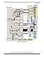
1
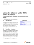
3-Phase AC Induction Motor Control
with PFC Using MC9S08MP16
Design Reference Manual
Devices Supported:
MC9S08MP16
Document Number: DRM115
Rev. 0
11/2009
How to Reach Us:
Home Page:
www.freescale.com
E-mail:
[email protected]
USA/Europe or Locations Not Listed:
Freescale Semiconductor
Technical Information Center, CH370
1300 N. Alma School Road
Chandler, Arizona 85224
+1-800-521-6274 or +1-480-768-2130
[email protected]
Europe, Middle East, and Africa:
Freescale Halbleiter Deutschland GmbH
Technical Information Center
Schatzbogen 7
81829 Muenchen, Germany
+44 1296 380 456 (English)
+46 8 52200080 (English)
+49 89 92103 559 (German)
+33 1 69 35 48 48 (French)
[email protected]
Japan:
Freescale Semiconductor Japan Ltd.
Headquarters
ARCO Tower 15F
1-8-1, Shimo-Meguro, Meguro-ku,
Tokyo 153-0064, Japan
0120 191014 or +81 3 5437 9125
[email protected]
Asia/Pacific:
Freescale Semiconductor China Ltd.
Exchange Building 23F
No. 118 Jianguo Road
Chaoyang District
Beijing 100022
China
+86 10 5879 8000
[email protected]
For Literature Requests Only:
Freescale Semiconductor Literature Distribution Center
1-800-441-2447 or 303-675-2140
Fax: 303-675-2150
[email protected]
Information in this document is provided solely to enable system and
software implementers to use Freescale Semiconductor products. There are
no express or implied copyright licenses granted hereunder to design or
fabricate any integrated circuits or integrated circuits based on the
information in this document.
Freescale Semiconductor reserves the right to make changes without further
notice to any products herein. Freescale Semiconductor makes no warranty,
representation or guarantee regarding the suitability of its products for any
particular purpose, nor does Freescale Semiconductor assume any liability
arising out of the application or use of any product or circuit, and specifically
disclaims any and all liability, including without limitation consequential or
incidental damages. “Typical” parameters that may be provided in Freescale
Semiconductor data sheets and/or specifications can and do vary in different
applications and actual performance may vary over time. All operating
parameters, including “Typicals”, must be validated for each customer
application by customer’s technical experts. Freescale Semiconductor does
not convey any license under its patent rights nor the rights of others.
Freescale Semiconductor products are not designed, intended, or authorized
for use as components in systems intended for surgical implant into the body,
or other applications intended to support or sustain life, or for any other
application in which the failure of the Freescale Semiconductor product could
create a situation where personal injury or death may occur. Should Buyer
purchase or use Freescale Semiconductor products for any such unintended
or unauthorized application, Buyer shall indemnify and hold Freescale
Semiconductor and its officers, employees, subsidiaries, affiliates, and
distributors harmless against all claims, costs, damages, and expenses, and
reasonable attorney fees arising out of, directly or indirectly, any claim of
personal injury or death associated with such unintended or unauthorized
use, even if such claim alleges that Freescale Semiconductor was negligent
regarding the design or manufacture of the part.
Freescale™ and the Freescale logo are trademarks of Freescale
Semiconductor, Inc. The ARM POWERED logo is a registered trademark of
ARM Limited. ARM7TDMI-S is a trademark of ARM Limited.
Java and all other Java-based marks are trademarks or registered
trademarks of Sun Microsystems, Inc. in the U.S. and other countries.
The PowerPC name is a trademark of IBM Corp. and is used under license.The
described product contains a PowerPC processor core. The PowerPC name is
a trademark of IBM Corp. and used under license. The described product is a
PowerPC microprocessor. The PowerPC name is a trademark of IBM Corp.
and is used under license. The described product is a PowerPC
microprocessor core. The PowerPC name is a trademark of IBM Corp. and is
used under license. All other product or service names are the property of their
respective owners.
© Freescale Semiconductor, Inc. 2008. All rights reserved.
DRM115
Rev. 0
11/2009
Chapter 1
Introduction
1.1
1.2
1.3
Introduction . . . . . . . . . . . . . . . . . . . . . . . . . . . . . . . . . . . . . . . . . . . . . . . . . . . . . . . . . . . .1
1.1.1 Application Features and Components . . . . . . . . . . . . . . . . . . . . . . . . . . . . . . . . .1
1.1.2 Overview of Variable Speed Drives . . . . . . . . . . . . . . . . . . . . . . . . . . . . . . . . . . .2
Freescale Controller Advantages and Features . . . . . . . . . . . . . . . . . . . . . . . . . . . . . . . .3
1.2.1 Peripheral Application Usage . . . . . . . . . . . . . . . . . . . . . . . . . . . . . . . . . . . . . . . .4
Bibliography . . . . . . . . . . . . . . . . . . . . . . . . . . . . . . . . . . . . . . . . . . . . . . . . . . . . . . . . . . . .6
1.3.1 Acronyms and Abbreviations . . . . . . . . . . . . . . . . . . . . . . . . . . . . . . . . . . . . . . . .6
1.3.2 Glossary of Symbols . . . . . . . . . . . . . . . . . . . . . . . . . . . . . . . . . . . . . . . . . . . . . . .7
Chapter 2
Control Theory
2.1
2.2
2.3
2.4
2.5
3-Phase AC Induction Motor . . . . . . . . . . . . . . . . . . . . . . . . . . . . . . . . . . . . . . . . . . . . . . .1
AC Induction Motor Scalar Control . . . . . . . . . . . . . . . . . . . . . . . . . . . . . . . . . . . . . . . . . .3
2.2.1 Volts-per-Hertz Control . . . . . . . . . . . . . . . . . . . . . . . . . . . . . . . . . . . . . . . . . . . . .4
2.2.2 Constant Slip Control . . . . . . . . . . . . . . . . . . . . . . . . . . . . . . . . . . . . . . . . . . . . . .5
2.2.3 Open-Loop Startup . . . . . . . . . . . . . . . . . . . . . . . . . . . . . . . . . . . . . . . . . . . . . . . .7
2.2.4 Digital Control of an AC Induction Motor . . . . . . . . . . . . . . . . . . . . . . . . . . . . . . .7
Speed Sensing Using AC Tacho Generator . . . . . . . . . . . . . . . . . . . . . . . . . . . . . . . . . . .8
Power Factor Correction Control . . . . . . . . . . . . . . . . . . . . . . . . . . . . . . . . . . . . . . . . . . . .9
2.4.1 PFC Critical Conduction Mode Implementation . . . . . . . . . . . . . . . . . . . . . . . . . 10
Current Sensing — Flex Timer and ADC Synchronization . . . . . . . . . . . . . . . . . . . . . . . 12
Chapter 3
System Concept
3.1
3.2
Application Description . . . . . . . . . . . . . . . . . . . . . . . . . . . . . . . . . . . . . . . . . . . . . . . . . . .1
Control Process . . . . . . . . . . . . . . . . . . . . . . . . . . . . . . . . . . . . . . . . . . . . . . . . . . . . . . . . .1
Chapter 4
Hardware
4.1
4.2
4.3
4.4
4.5
Hardware Implementation . . . . . . . . . . . . . . . . . . . . . . . . . . . . . . . . . . . . . . . . . . . . . . . . .1
MC9S08MP16 Daughter Board for UHV Power Stage . . . . . . . . . . . . . . . . . . . . . . . . . . .2
3-Phase Universal High Voltage Power Stage . . . . . . . . . . . . . . . . . . . . . . . . . . . . . . . . . .3
PFC Board . . . . . . . . . . . . . . . . . . . . . . . . . . . . . . . . . . . . . . . . . . . . . . . . . . . . . . . . . . . . .6
Motor Specifications — Example . . . . . . . . . . . . . . . . . . . . . . . . . . . . . . . . . . . . . . . . . . . .7
3-Phase AC Induction Motor Control with PFC Using MC9S08MP16, Rev. 3
Freescale Semiconductor
1
Chapter 5
Software Design
5.1
5.2
5.3
5.4
5.5
5.6
5.7
5.8
Introduction . . . . . . . . . . . . . . . . . . . . . . . . . . . . . . . . . . . . . . . . . . . . . . . . . . . . . . . . . . . .1
Main Software Flowchart . . . . . . . . . . . . . . . . . . . . . . . . . . . . . . . . . . . . . . . . . . . . . . . . . .1
Application Overview . . . . . . . . . . . . . . . . . . . . . . . . . . . . . . . . . . . . . . . . . . . . . . . . . . . . .2
Software States . . . . . . . . . . . . . . . . . . . . . . . . . . . . . . . . . . . . . . . . . . . . . . . . . . . . . . . . .3
5.4.1 Initialization . . . . . . . . . . . . . . . . . . . . . . . . . . . . . . . . . . . . . . . . . . . . . . . . . . . . . .5
5.4.2 Application Background Loop . . . . . . . . . . . . . . . . . . . . . . . . . . . . . . . . . . . . . . . .6
5.4.3 Interrupts . . . . . . . . . . . . . . . . . . . . . . . . . . . . . . . . . . . . . . . . . . . . . . . . . . . . . . .6
5.4.4 Library Functions . . . . . . . . . . . . . . . . . . . . . . . . . . . . . . . . . . . . . . . . . . . . . . . . .8
FreeMASTER Software . . . . . . . . . . . . . . . . . . . . . . . . . . . . . . . . . . . . . . . . . . . . . . . . . . .8
5.5.1 FreeMASTER Serial Communication Driver . . . . . . . . . . . . . . . . . . . . . . . . . . . . .9
5.5.2 FreeMASTER Recorder . . . . . . . . . . . . . . . . . . . . . . . . . . . . . . . . . . . . . . . . . . . 10
5.5.3 FreeMASTER Control Page . . . . . . . . . . . . . . . . . . . . . . . . . . . . . . . . . . . . . . . . 10
Setting the Software Parameters for a Specific Motor . . . . . . . . . . . . . . . . . . . . . . . . . . . 11
Microcontroller Memory Usage . . . . . . . . . . . . . . . . . . . . . . . . . . . . . . . . . . . . . . . . . . . . 12
Conclusion . . . . . . . . . . . . . . . . . . . . . . . . . . . . . . . . . . . . . . . . . . . . . . . . . . . . . . . . . . . . 12
3-Phase AC Induction Motor Control with PFC Using MC9S08MP16, Rev. 3
2
Freescale Semiconductor
Chapter 1
Introduction
1.1
Introduction
This document describes the cost-effective design of a three-phase AC induction motor, V/Hz and CSC
(constant slip control) closed-loop speed control, and digital power factor correction (PFC) using
the MC9S08MP16. The design is targeted at consumer and industrial applications. This cost-effective
solution benefits from the dedicated motor control features in the Freescale Semiconductor MC9S08MP16
device.
1.1.1
Application Features and Components
The system is designed to drive a three-phase AC induction motor. The application features:
• Targeted at the MC9S08MP16 8-bit microcontroller.
• Three-phase ACIM control using tacho generator as a rotary transducer.
— Two control algorithms incorporating (optionally set from FreeMASTER).
– V/Hz closed speed loop.
– Constant (optimal) slip control in nominal speed range.
— Controlled acceleration and deceleration.
— Bidirectional rotation.
— Both motor and generator modes.
— PWM frequency 16 kHz.
— Operation in FreeMASTER or demo operating mode.
— Software over-voltage and under-voltage protection.
— Hardware over-current protection.
• Power Factor Correction (PFC).
— Automatic input voltage detection 110 V/60 Hz and 230 V/50 Hz.
— DC-bus voltage regulation: 390 V DC, 5% ripple for Pout = 300 W.
— Over voltage protection.
— Power factor: > 0.94 @ 230 V AC.
• Three-phase high-voltage (230/115 V) power board.
• High-voltage daughter controller board.
• PFC board with input filter.
• FreeMASTER software control interface (motor start/stop, speed setup).
3-Phase AC Induction Motor Control with PFC Using MC9S08MP16, Rev. 0
Freescale Semiconductor
1
Introduction
•
FreeMASTER software monitor.
— FreeMASTER software graphical control page (required speed, actual motor speed, start/stop
status, DC-bus voltage level, motor current, system status).
— FreeMASTER software speed scope (actual and desired speeds, DC-bus voltage, and motor
current).
Figure 1-1. 3-Phase AC Motor Control with V/Hz CSC Speed Close Loop and PFC using MC9S08MP16
The main application components available for customers are:
• Software — written in C-code using some library algorithms available for the HCS08.
• Hardware — based on the Freescale universal motor-control hardware modules.
• Documentation — this document.
1.1.2
Overview of Variable Speed Drives
The design of cost-effective variable-speed 3-phase motor control drives has become a prime focus point
for the appliance designers and semiconductor suppliers. Replacing variable-speed universal motors by
maintenance-free, low-noise asynchronous (induction) motors is a trend that supposes total system costs
being equivalent. The big push in this direction is given by several factors:
• The new IEC555-1, European Community regulations dealing with electrical noise in power
distribution.
• Lines and low power consumption.
• The flexibility that can be achieved in using asynchronous motors with variable frequency.
3-Phase AC Induction Motor Control with PFC Using MC9S08MP16, Rev. 0
2
Freescale Semiconductor
Introduction
•
•
•
The maturity level and affordable price trend of power devices.
The system efficiency optimization that microprocessor-controlled drives can provide.
The size, weight, and dissipated power reduction of the motors for a given mechanical power.
Most usual variable speed ac induction motor drive designs contain a full-bridge rectifier and a large
DC-bus capacitor at the input. Such a circuit draws a peak current from the wall socket, which provokes a
high content of harmonics. The low-power factor (PF), as described in the present circuit, reduces the
necessary power from the mains and increases the efficiency of the mains supply network.
The international standard IEC1000-3-2 defines the limits of the harmonic content of the input current for
mains-supplied equipment. To meet the norms, the design requires a power factor correction at the input.
The present design allows simultaneous driving of the power factor correction algorithm and the AC
induction motor. This way, significant cost reductions of the design can be achieved. Moreover, a wide
range of input voltages from 90 V to 265 V AC and regulation of DC-bus voltage can be achieved. Another
benefit of the design is the possibility of an easy modification of the system by software updates.Two key
requirements of the described design are that it has to be cost-effective and highly reliable.
This design reference manual describes the basic motor theory, system design concept, hardware
implementation, and software design, including the FreeMASTER software visualization tool.
1.2
Freescale Controller Advantages and Features
The MC9S08MP16 is a member of the low-cost, high-performance HCS08 Family of 8-bit
microcontroller units (MCUs). All MCUs in this family use the enhanced HCS08 core and are available
with a variety of modules, memory sizes, memory types, and package types.
The Freescale MC9S08MP16 microcontroller is well-suited for digital motor control offering many
dedicated peripherals, such as Flextimer (FTM) modules, analog-to-digital converters (ADC), timers,
communications peripherals (SCI, SPI, I2C), and onboard flash and RAM.
The MC9S08MP16 device provides the following features:
• Two Flextimer modules with a total of eight channels.
• One analog-to-digital converter (ADC) 13-channel, 12-bit resolution, 2.5 µs conversion time.
• One 8-bit modulo counter with an 8-bit prescaler and overflow interrupt.
• Interrupt Priority Controller (IPC) with four programmable interrupt priority levels.
• One differential Programmable Gain Amplifier (PGA) with programmable gain (x1, x2, x4, x8,
x16, or x32).
• Three fast analog comparators (HSCMP1, HSCMP2, and HSCMP3) with both positive and
negative inputs.
• Three 5-bit digital-to-analog converters (DAC) used as a 32 tap voltage reference.
• Two programmable delay blocks (PDB). PDB1 synchronizes the PWM with samples of the ADC,
PDB2 synchronizes the PWM with comparing window of analog comparators, PWM output
synchronizes with FTM PWM output.
• One serial peripheral interface (SPI).
• One serial communications interface (SCI) with LIN slave functionality.
3-Phase AC Induction Motor Control with PFC Using MC9S08MP16, Rev. 0
Freescale Semiconductor
3
Introduction
•
•
•
•
•
•
•
•
1.2.1
One inter-integrated circuit (I2C) port.
Onboard 3.3 V to 2.5 V voltage regulator for powering internal logic and memories.
Integrated power-on reset and low-voltage interrupt module.
Multiplexing of all pins with general-purpose input/output (GPIO) pins.
Computer-operating-properly (COP) watchdog timer
External reset input pin for hardware reset
Single-wire background debug interface (BDM).
Internal Clock Source (ICS) — Containing a frequency-locked-loop (FLL) controlled by internal
or external reference.
Peripheral Application Usage
The ACIM V/Hz and CSC with PFC benefits greatly from the flexible PWM module, fast ADC,
high-speed comparators HSCMP, program delay block PDB, and modulo timer MTIM.
The Flex Timer offers flexibility in its configuration, enabling efficient three-phase motor control. Each
FTM module supports an initialization trigger function which is used to trigger both PDBs.
The FTM1 (Flex Timer module) features used in the application:
• Input capture mode for tacho period signal measurement.
• HSCMP output connected to the FTM1 input.
The FTM2 (Flex Timer module) features used in the application:
• Generation of six PWM signals.
• Set combine mode with complementary outputs.
• Dead time inserted.
• Fault protection enabled for external over-current fault trigger.
• Synchronized PWM register update on timer-overflow event.
• Hardware trigger generation for ADC synchronization with the PWM signal (optional feature, not
required for application functionality).
The ADC features used in the application:
• Hardware trigger for the ADC start generated by the PDB1.
• Linear successive approximation algorithm with 12-bit resolution.
• High-speed conversion.
• 5 MHz module clock.
The PDB1 (Program delay block) features used in the application (optional, not required):
• The controllable delay from the Flextimer module’s SYNC output to the sample trigger input of
the programmable gain amplifiers and ADC.
3-Phase AC Induction Motor Control with PFC Using MC9S08MP16, Rev. 0
4
Freescale Semiconductor
Introduction
The PDB2 features used in the application:
• Single-shot mode,
• Output PWM PFC pulse generation with precisely controlled rising and falling times,
• Both hardware and software triggering.
The HSCMP1 (High-speed comparator) features used in the application:
• Input current zero-cross detection for PFC,
• Compare level set by the DAC1,
• Inversion on comparator output,
• Output used for hardware trigger.
The HSCMP2 features used in the application:
• Comparator of tacho signal,
• Compare level set by DAC2,
• Output used for period measurement.
The HSCMP3 features used in the application:
• Input low voltage level detection,
• Compare level set by DAC3.
The DACx features used in the application:
• Set compare level for each HSCCMPx.
The MTIM (Modulo timer) features used in the application:
• 8-bit modulo limit running,
• Set time base for a 1 ms loop,
• Overflow interrupt generation.
3-Phase AC Induction Motor Control with PFC Using MC9S08MP16, Rev. 0
Freescale Semiconductor
5
Introduction
1.3
Bibliography
1. 3-Phase Universal High Voltage Power Stage User’s Manual, Freescale Semiconductor, 2009
2. MC9S08MP16 Daughter Board for UHV Power Stage User’s Manual, Freescale Semiconductor,
2009
3. PFC Board User’s Manual, Freescale Semiconductor, 2009
4. MC9S08MP16 Reference Manual, Freescale Semiconductor, 2008
5. Code Warrior Development Studio for Freescale Microcontrollers V6.2, Freescale Semiconductor,
2008
6. AN2395 — PC Master Software Usage, Freescale Semiconductor, 2002
7. 3-Phase PM Synchronous Motor Vector Control, AN1931, by Prokop L., Grasblum P., 2005
8. Embedded Software Library for S08 User’s Manual, Freescale Semiconductor, 2009
For a current list of documentation, refer to www.freescale.com.
1.3.1
Acronyms and Abbreviations
Table 1-1 contains sample acronyms and abbreviations used in a document.
Table 1-1. Acronyms and Abbreviated Terms
Term
Meaning
AC
Alternating current
ACIM
AC Induction Motor
ADC
Analog-to-digital converter
BDM
Background Debug Mode
COP
Computer Operating Properly (watchdog timer)
CSC
Constant Slip Control
DT
GPIO
I/O
LED
Dead time: a short time that must be inserted between the turning off of one transistor in the inverter half
bridge and turning on of the complementary transistor, due to the limited switching speed of the transistors
General-purpose input/output
Input/output interfaces between a computer system and the external world — a CPU reads an input to sense
the level of an external signal and writes to an output to change the level of an external signal
Light-emitting diode
MC9S08MP16 A Freescale family of HCS08 dedicated to motor control
PFC
Power Factor Correction
PLL
Phase-locked loop: a clock generator circuit in which a voltage-controlled oscillator produces an oscillation
that is synchronized to a reference signal
PWM
Pulse-width modulation
RPM
Revolutions per minute
3-Phase AC Induction Motor Control with PFC Using MC9S08MP16, Rev. 0
6
Freescale Semiconductor
Introduction
Table 1-1. Acronyms and Abbreviated Terms (continued)
Term
Meaning
SCI
Serial communication interface module: a module that supports asynchronous communication
V/Hz
Volts per Hertz
1.3.2
Glossary of Symbols
Table 1-2 shows a glossary of symbols used in this document.
Table 1-2. Glossary of Symbols
Term
Definition
ns
synchronous stator speed
fs
synchronous stator frequency
pp
stator pole-pair number
p
stator pole number
ωslip
relative angular velocity
ωs
flux wave velocity
ωr
mechanical angular velocity
3-Phase AC Induction Motor Control with PFC Using MC9S08MP16, Rev. 0
Freescale Semiconductor
7
Introduction
3-Phase AC Induction Motor Control with PFC Using MC9S08MP16, Rev. 0
8
Freescale Semiconductor
Chapter 2
Control Theory
2.1
3-Phase AC Induction Motor
The AC induction motor is a rotating electric machine designed to operate from a 3-phase source of
alternating voltage. For variable speed drives, the source is normally an inverter that uses power switches
to produce approximately sinusoidal voltages and currents of controllable magnitude and frequency.
The stator is supplied by a balanced three-phase AC power source. The synchronous speed of the motor
(ns) is given by
2 × 60 × π × f
n s = -----------------------------------s
p
[rpm]
Eqn. 2-1
where fs is the synchronous stator frequency in Hz, and p is a stator pole number.
A cross-section of a two-pole induction motor is shown in Figure 2-1. Slots in the inner periphery of the
stator accommodate the 3-phase windings a,b,c. The turns in each winding are distributed so that the
current in the stator winding produces an approximately sinusoidally-distributed flux density around the
periphery of the air gap. When the three currents that are sinusoidally varying in time, but displaced in
phase by 120° from each other, flow through the three symmetrically-placed windings, a radially-directed
air gap flux density is produced that is also sinusoidally distributed around the gap, and rotates at an
angular velocity equal to the angular frequency of the stator currents.
The most common type of an induction motor has a squirrel cage rotor in which aluminum conductors or
bars are cast into the slots in the outer periphery of the rotor. These conductors or bars are shorted together
at both ends of the rotor by cast aluminum end rings, which also can be shaped to act as fans. In larger
induction motors, copper or copper-alloy bars are used to fabricate the rotor cage winding.
3-Phase AC Induction Motor Control with PFC Using MC9S08MP16, Rev. 0
Freescale Semiconductor
1
Control Theory
Stator Rotor
b
c'
w
a'
a
c
b'
Figure 2-1. PM Synchronous Motor — Cross Section
As the sinusoidally-distributed flux density wave produced by the stator magnetizing currents sweeps past
the rotor conductors, it generates voltage in them. The result is a sinusoidally-distributed set of currents in
the short-circuited rotor bars. Because of the low resistance of these shorted bars, only a small relative
angular velocity between the angular velocity of the flux wave (ωs) and the mechanical angular
velocity (ω) of the two-pole rotor is required to produce the necessary rotor current. The relative angular
velocity is called the slip velocity (ωslip).
ω slip = ω s – ω r
[rad.s-1]
Eqn. 2-2
The interaction of the sinusoidally-distributed air gap flux density and induced rotor currents produces a
torque in the rotor. The typical induction motor speed-torque characteristic is shown in Figure 2-2.
3-Phase AC Induction Motor Control with PFC Using MC9S08MP16, Rev. 0
2
Freescale Semiconductor
Control Theory
Figure 2-2. AC Induction Motor Speed-Torque Characteristic
Squirrel-cage AC induction motors are popular because of their simple construction, low cost per
horsepower and low maintenance (they contain no brushes, as do DC motors). They are available in a wide
range of power ratings. With field-oriented vector control methods, AC induction motors can fully replace
the standard DC motors, even in high-performance applications.
2.2
AC Induction Motor Scalar Control
Two speed-control algorithms are incorporated in the presented application — Volts per Hertz and
Constant Slip Control. The user can choose one of them using either definitions in the source code (located
at the beginning of the main.c file) or the FreeMASTER control page. Both control methods are described
in the following chapters.
3-Phase AC Induction Motor Control with PFC Using MC9S08MP16, Rev. 0
Freescale Semiconductor
3
Control Theory
2.2.1
Volts-per-Hertz Control
The Volts-per-Hertz control method is the most popular method of Scalar Control which controls the
magnitude of variables such as frequency, voltage, or current. The command and feedback signals are DC
quantities that are proportional to the respective variables.
A simple open-loop Volts/Hertz speed control for an induction motor is the control technique targeted at
low-cost, low-performance drives. This basic scheme is unsatisfactory for more demanding applications
where torque control is required. This drawback can be partly compensated for by implementing a
closed-loop speed control with a speed sensor as a feedback quantity.
This scheme is defined as a Volts-per-Hertz control because the voltage applied command is calculated
directly from the applied frequency in order to maintain the air-gap flux of the machine constant. In a
steady state operation, if it is assumed that there is a negligible voltage drop across the stator resistor, the
machine air-gap flux is approximately proportional to the ratio Vs/fs, where Vs is the amplitude of a motor
phase voltage and fs is the synchronous electrical frequency applied to the motor. However, when the
frequency and voltage are low, the voltage drop across the stator resistance cannot be neglected and has to
be compensated for.
The control system is illustrated in Figure 2-3. The characteristic is defined by the base point (usually
50 Hz or 60 Hz) of the motor. Below the base point, the motor operates at optimum excitation, called
constant torque operation, because of the constant Vs/fs ratio. Above this point, the motor operates
under-excited, called constant power operation, because of the rated voltage limit. Since the air-gap flux
is a maintained constant (constant Vs/fs ratio), independent of the applied synchronous electrical frequency,
the torque produced depends on the slip frequency only. Thus, regulating the slip frequency, the torque and
speed of the ACIM can be controlled with the constant V/Hz technique.
Figure 2-3. Volts-per-Hertz Control Method
Unfortunately, the Volts-per-Hertz ramp is designed for nominal motor / load conditions. If the conditions
are not nominal, the motor does not work at the optimal level and the performance and efficiency are bad.
The optimal slip-control algorithm resolves such disadvantages.
3-Phase AC Induction Motor Control with PFC Using MC9S08MP16, Rev. 0
4
Freescale Semiconductor
Control Theory
2.2.2
Constant Slip Control
From motor-control theory, it is known that a slip frequency exists when the motor efficiency is at its
highest. Close to that slip frequency there is another where the phase current is at its lowest — this means
that the inverter losses are the lowest. The compromise between these two parameters is the constant
(optimal) slip frequency when the system efficiency is the best. This optimal slip frequency significantly
depends neither on electrical sine frequency nor the motor load. The optimal slip frequency can be
determined by the drive efficiency measurement or by a calculation. To control a drive with high efficiency,
this feature is applied.
The system concept of a constant slip speed closed loop control is shown in Figure 2-4.
MC9S08MP16
Speed Command
FreeMASTER
Speed
Ramp
Required
Speed
+
Voltage
Amplitude
V/Hz
Sine
PWM
Generation
Max. Voltage
+
Integrator
U
V
W
Phase
+
Fault
Processing
Optimal Slip
Actual Speed
Speed
Calculation
Tacho Signal
Figure 2-4. Control Concept
The speed closed loop control is characterized by the measurement of the actual motor speed. This value
is compared with the reference value (required speed as an output of the speed ramp), and the error signal
is generated. The magnitude and polarity of the error signal corresponds to the difference between the
actual and required speed. The PI controller generates stator voltage amplitude value, based on the speed
error, in order to compensate the error.
A 3-phase motor is supplied with sinusoidal voltage wave generated by the PWM unit (FTM2) of the
microcontroller. The parameters are the frequency phase and the voltage amplitude.
Control algorithm calls one of the control modes depending on motor conditions:
• Amplitude < 100% — VOLTAGE CONTROL, see Figure 2-5
— The frequency is calculated as the sum of the actual speed and the optimal slip frequency (4 Hz
for the tested drive).
— The voltage is adapted according to the load using a PI controller. It means that for different
loads the amplitude of the supply voltage differs.
3-Phase AC Induction Motor Control with PFC Using MC9S08MP16, Rev. 0
Freescale Semiconductor
5
Control Theory
PWM's
Speed
Command
Speed
Ramp
Required
Speed +
Error
Amplitude
PI
Controller
+
Sine PWM
Generation
Output Sine
Frequency
Sine phase
Integrator
+
Actual Motor Speed
Optimal Slip
Figure 2-5. Voltage Control Concept
•
Amplitude reaches 100% — FREQUENCY CONTROL, see Figure 2-6
— For higher speeds and heavy loads, when the amplitude given by the PI output reaches the
maximum value, it is necessary to increase the slip of the motor in order to achieve the desired
speed.
— The output voltage amplitude is a maintained constant — maximal.
— The machine transits to the field-weakening region. In this region the efficiency of the drive is
decreased due to the slip increase.
PWM's
Amplitude = AMPLITUDE_MAX
Speed
Command
Speed
Ramp
Required
Speed +
Error
PI
Controller
Sine PWM
Generation
Output Sine
Frequency
Sine phase
Integrator
Actual Motor Speed
Figure 2-6. Frequency Control Concept
In the case of an inertial load, the motor can work like a generator during deceleration. In opposite to a
simple V/Hz drive, the generator mode must be detected and the control algorithm adapted. The control
error of the PI controller E(n) has to be calculated differently.
The generator region is sensed using following condition:
IF
(Actual rotor frequency > Generated stator frequency)
THEN
=>
generator region
ELSE
=>
motor region
3-Phase AC Induction Motor Control with PFC Using MC9S08MP16, Rev. 0
6
Freescale Semiconductor
Control Theory
In the MOTOR region the control error E(n) is calculated as follows:
Error = RequiredSpeed – ActualSpeed
In the GENERATOR region the control error E(n) is calculated as follows:
Error = ActualSpeed – (RequiredSpeed + 2 x OptimalSlip)
The rest of the control strategy is the same for both motor and generator regions.
2.2.3
Open-Loop Startup
The application utilizes an open-loop startup from zero up to the minimal measurable rotor speed.
The generated tacho voltage is proportional to motor rotation, and it generates an incomparable voltage
signal from a zero speed up to the minimal measurable rotor speed (see 2.3, “Speed Sensing Using AC
Tacho Generator”). Because of this speed sensor drawback during the motor startup, the actual tacho speed
is set to a minimal measurable speed which enables generating a speed error for the PI controller. When
the rotor speed can be sensed, the speed control loop is closed.
2.2.4
Digital Control of an AC Induction Motor
In adjustable speed applications, AC motors are powered by inverters. The inverter converts a DC power
to an AC power at the required frequency and amplitude. Figure 2-7 illustrates a typical 3-phase inverter.
+ DC-Bus
C
+
- DC-Bus
Ph. B
Ph. A
Ph. C
3-Phase
AC Motor
Figure 2-7. Power Stage Schematic Diagram
The inverter consists of three half-bridge units where the upper and lower switches are controlled
complementarily, meaning when the upper one is turned on, the lower one must be turned off, and vice
versa. Because the power device’s turn-off time is longer than its turn-on time, some dead time must be
inserted between turning off one transistor of the half-bridge, and turning on its complementary device.
The output voltage is mostly created by a pulse width modulation (PWM) technique. The 3-phase voltage
waves are shifted 120° to each another, thus a 3-phase motor can be supplied.
3-Phase AC Induction Motor Control with PFC Using MC9S08MP16, Rev. 0
Freescale Semiconductor
7
Control Theory
2.3
Speed Sensing Using AC Tacho Generator
A tacho generator is a precision shaft-mounted generator used to sense mechanical speed of motor rotation.
It generates an AC voltage which is highly linear in proportion to the actual motor speed and is used as a
feedback signal required for a speed control loop.The precision of speed measurement depends on the
tacho generator pole-pair number. In the application, the 8-pole-pair tacho generator is used.
This generates eight periods of sinusoidal signal per each mechanical revolution.
The biggest problem of using a tacho as a motor speed transducer is that it does not work at zero and low
speed operations which have to be compensated for by software. The actual speed is calculated in the
10 ms loop.
As a comparator, the on-chip HSCMP2 (High Speed Comparator) is used. The analog signal is limited to
3.3 V and connected to HSCMP2 positive input P1. The compared value is set by the internal DAC2 and
connected to HCSCMP2 minus input M4.
The comparator output is internally connected to the FTM1 input and, using a capture event, the period
between the two comparator signal edges is obtained. The actual motor speed is then evaluated from the
captured tacho period.
System configuration is shown in Figure 2-8.
MC9S08MP16
HSCMP2
FTM1
Passive
ACIM
Capture
Input
Input M4
Tacho period
Output
Filter
Input
Input P1
DAC2
Clk
System clock / 8
Output
Figure 2-8. Tacho System Configuration
The actual rotor frequency can be expressed as:
speed
k
speed = --kT
Eqn. 3
FTMfreq
k = ------------------------------------------------------------4 × StatorMaxFreq × p p
Eqn. 4
calculated actual rotor frequency[Hz]
scaling constant[-]
3-Phase AC Induction Motor Control with PFC Using MC9S08MP16, Rev. 0
8
Freescale Semiconductor
Control Theory
T
FTMfreq
StatorMaxFreq
pp
period of a half motor mechanical revolution[s]
FlexTMR frequency for tacho edge input capture[Hz]
Maximal scaling stator frequency[Hz]
motor pole-pair number[Hz]
The rotor frequency is calculated using the tacho generator frequency value per half of a motor mechanical
revolution. The timer FTM1, running with frequency FTMfreq, is employed for capturing the edges
coming from the internal high-speed comparator HSCMP2.The minimum rotor frequency which can be
detected using the presented tacho generator is set to 1.2 Hz, while the maximum measurable speed is
limited to 100 Hz in the presented application.
2.4
Power Factor Correction Control
The boost and the buck/boost topologies are popular within the field, since they produce a higher DC
output voltage than the peak input voltage, which means lower average output currents. The basic topology
of a boost converter is shown in Figure 2-9.
The boost topology has become the most popular topology. A low-side power switch enables utilizing a
simple control technique. Its only restriction is that the DC output voltage is higher than the highest
expected AC voltage amplitude.
Filter + Rectifier
L
D
+
~
C1
S
C2
AC 230V
Control
=
Output
voltage
380 V
-
Figure 2-9. Boost PFC Converter Concept
Control of the power factor correction stage is a point of discussion and patent battling.
There are three general methods of control:
• fixed on-time mode
• critical conduction mode (discontinuous)
• continuous mode
Fixed on-time mode conversion consists of the minimum amount of circuitry, but output current is limited
to lower values. Critical conduction mode conversion incorporates no output rectifier reverse recovery
losses, but output power is limited to the range of 300 to 600 W. Continuous mode boost PFC circuits can
achieve much higher output power, but this brings significant rectifier reverse recovery losses. However,
some zero-transition loss circuits are implemented, and the overall system cost is increased.
Additional cost is very important in this area, since the power factor correction is an invisible benefit to the
customers who do not want to pay for anything which cannot be seen directly. The critical conduction
mode is considered as most suitable for the presented application concept.
3-Phase AC Induction Motor Control with PFC Using MC9S08MP16, Rev. 0
Freescale Semiconductor
9
Control Theory
2.4.1
PFC Critical Conduction Mode Implementation
The PFC can be incorporated as a part of every system which is supplied from the AC mains. This section
describes the implementation of the PFC running in Critical Conduction Mode into 3-phase ACIM V/Hz
control.
The system concept is shown in Figure 2-10.
PWM signal generation for the PFC switch is performed by the on-chip peripheral PDB2 set to mode
ONE-SHOT and the registers set to the following values:
• PDB2DLYA = 1 (constant value)
• PDB2DLYB = duty cycle — PI controller output value calculated in the 1 ms loop
The variable switching frequency depends on the input voltage, the level, and level of output current.
The duty cycle of the PWM pulses is defined by the voltage PI controller, the PWM period is defined by
the input current zero cross detection. The timing diagram shows PFC PWM signal generation
(see Figure 2-11).
V in
Vout
Filter + Rectifier
AC 230V
~
t
DC - BUS
D
t
+
V in
TPFC
C1
Output
voltage
380 V
L
=
-
RGATE
Zero - detect
Power
Supply
t
PWM
PFC Driver
S08MP16
Zero - detect
+
Ref. DAC1
+
V DCreq
e
Period
PDB2
Duty Cycle
-
Vin
Ref. DAC3
HSCMP1
PDB2DLYB
PDB2DLYA
EN/DI
HSCMP3
-
Enable/Disable
PWM + Sw. TRIG
PI controller
ADC
Module
Over-voltage
protection
V DCactual
Figure 2-10. PFC System Concept
3-Phase AC Induction Motor Control with PFC Using MC9S08MP16, Rev. 0
10
Freescale Semiconductor
Control Theory
Voltage [V]
Zero current
detect of PFC
inductor
Ext.trig
T [ Ps ]
Counter reg.
of PDB timer [-]
PDB2DLYB
PDB2DLYA =1
T [ Ps ]
Voltage [V]
Duty cycle
PWM
output
T [ Ps ]
Switching periode
Figure 2-11. PFC PWM Generation Timing
In a normal operation, the PDB2 Timer is restarted by an inductor current zero-crossing signal.
The red area in Figure 2-12 indicates the state when the inductor current zero-crossing signal is lost. In this
case, the PDB2 timer must be restarted by a software trigger because the current zero-crossing signal is
not available when the input line voltage signal is close to zero. The red area is detected when the input
voltage falls under a certain level (typically 35 V). This level indicates the setting of fall compare flag
in HSCMP3. When the input voltage level rises again and the rise-compare flag is set in HSCMP3, PDB2
is switched back to a hardware trigger.
Vin
ref. V in
HSCMP3 rise flag
HSCMP3 fall flag
zero detect is
lost
HSCMP3 Out
Disable PWM
time [ms]
Enable PWM +
SW. TRIG.
450 Ps
time [ms]
Figure 2-12. PFC Critical Zero Detect Area
3-Phase AC Induction Motor Control with PFC Using MC9S08MP16, Rev. 0
Freescale Semiconductor
11
Control Theory
2.5
Current Sensing — Flex Timer and ADC Synchronization
This optional configuration shows how the AD converter module can by synchronized with the Flex Timer
using a PDB. It enables sensing the proper quantities of the phase or DC-bus currents at the instant when
current flows via the sensing shunt. The sensed current is only an informative value and is not required in
the presented control algorithm. The over-current state is detected by the power module and the fault signal
is detected as an FTM fault trigger.
Other quantity sensing (DC-bus and input voltage) can be triggered by the ADC software trigger without
the necessity of a synchronization with the Flex Timer.
The FTM2 module is configured to run in combined center-aligned mode, with counter modulo
FTM2MOD = 1249, and the counter initialization register FTM2CNTIN = –1250, which enable a
center-aligned mode with a switching frequency of 16 kHz at a 40 MHz system clock (PWM cycle period
= 62.5 μs).
The synchronization signal is generated every PWM cycle with a 62.5 μs period. The synchronization
signal is connected to the PDB1 module (program delay block) to synchronize the PWM signal with
analog quantity sensing.
The PDB1 module is configured in triggered mode, synchronized with a FTM2 rollover event. Delayed
output triggers the AD converter to read the DC-bus current samples in predefined time instants.
An overview of the module interconnections is shown in Figure 2-13.
PWM0
PWM1
PWM2
PWM3
PWM4
FTM2
Trigger 5
PDB1
PDB1 HW
trigger
ADC
PWM5
Figure 2-13. ADC Triggering
The timing diagram in Figure 2-14 shows how the triggered ADC conversion is performed. The events are
executed in the following steps, which are numbered in the figure.
1. The FTM2 counter reaches the MODULO value. The FTM2 overflow occurs and the counter is set
to zero. The FTM2 overflow flag (FTM2SC_TOF) is set to one and pending. The synchronization
signal TRIGGER 5 is generated by the FTM2 module.
2. PDB channel 1 count is triggered by the TRIGGER 5 signal, which is connected to its source input.
The timer starts counting up from zero.
3. A compare on the PDB1 DELAYB register occurs. The PDB1 output generates a synchronization
pulse for the ADC.
4. A rising edge on the hardware trigger input of the ADC module starts the ADC conversion.
3-Phase AC Induction Motor Control with PFC Using MC9S08MP16, Rev. 0
12
Freescale Semiconductor
Control Theory
5. The FTM2 ISR is pending. Previous AD conversion data is read, a new AD channel for the next
conversion is set. In one FTM2 ISR, the actual duty cycles are calculated and in the following
FTM2 ISR the values of the PWM register are updated. This means that the PWM register is
updated every second FTM2 period (2 x 62.5 = 125 μs). For a detailed description of the FTM2
ISR, follow 5.4.3.1, “FTM2 Overflow Interrupt.”
PWM Cycle
62.5μs
FTM2 Counter
1
Trigger 5
PDB1
Counter
2
PDB1 Compare
3
ADC Conversion
4
FTM2 Overflow ISR
5
Figure 2-14. ADC Synchronization with FTM2
3-Phase AC Induction Motor Control with PFC Using MC9S08MP16, Rev. 0
Freescale Semiconductor
13
Control Theory
3-Phase AC Induction Motor Control with PFC Using MC9S08MP16, Rev. 0
14
Freescale Semiconductor
Chapter 3
System Concept
3.1
Application Description
A standard system concept is chosen for the drive (see Figure 3-1). The system incorporates these
hardware boards:
• 3-Phase Universal High Voltage Power Stage,
• MC9S08MP16 Daughter Board for UHV Power Stage,
• PFC board with input line filter,
• 3-phase AC induction motor (default configuration for ATAS NT4C82 motor).
The MC9S08M16 populated on the controller daughter board executes the control algorithm. In response
to the user interface and feedback signals, it generates PWM signals for the three-phase high-voltage
power board. High-voltage waveforms generated by the DC to AC inverter are applied to the motor.
Input voltage is connected to the AC/DC converter utilizing the Power Factor Correction Board in order to
provide sinusoidal input current and to increase the PF (power factor) and THD (Total Harmonic
Distortion).
3.2
Control Process
The state of the speed transducer (tacho generator) is scanned periodically by the software timer loop,
while the speed of the motor is calculated utilizing the Input Capture interrupt. The speed command is
calculated according to the state of the control signals (Start/Stop, Required Speed from FreeMASTER).
Then the speed command is processed by means of the speed-ramp algorithm. The comparison between
the actual speed command obtained from the ramp algorithm output and the measured speed generates a
speed error. The speed error is processed by the speed PI controller that generates either a new corrected
motor voltage amplitude or stator frequency, depending on the control algorithm utilized. Using a V/Hz
ramp, the corresponding maximal voltage is calculated. The PWM generation process calculates a system
of 3-phase voltages of the required amplitude and frequency, including dead time, and finally the 3-phase
PWM motor-control signals are generated.
The input voltage, DC-bus voltage and DC-bus current (optional informative value) are measured during
the control process. They are used for PFC control (input voltage), over-voltage, under-voltage protection
(DC-bus voltage) and over-current protection (DC-bus current) of the drive. The voltage protection is
performed by means of software, whilst the over-current fault signal utilizes a fault input of
the microcontroller. If any of the above mentioned faults occur, the motor-control PWM outputs are
disabled in order to protect the drive and the fault state of the system is displayed.
3-Phase AC Induction Motor Control with PFC Using MC9S08MP16, Rev. 0
Freescale Semiconductor
1
System Concept
The power factor correction loop keeps a constant DC-bus voltage using the PI controller. The controller
output provides the required duty cycle of the PFC PWM signal which is generated by the PDB module.
The application can be controlled via a FreeMASTER control page from a host PC. The FreeMASTER
communicates via the USB interface. The USB connector is opto-isolated to achieve safety isolation from
high voltage.
The application state machine of the drive manages the operating states of the drive (FAULT, INIT,
CALIBRATION, and EXECUTE). The actual operating state is indicated by the FreeMASTER control
page. In the case of over-voltage, under-voltage or over-current, the signals for the three-phase inverter are
disabled and the fault state is displayed.
3-Phase AC Induction Motor Control with PFC Using MC9S08MP16, Rev. 0
2
Freescale Semiconductor
System Concept
Power Line
Input
PFC Board
MC9S08MP16
Vin
Processing
Vin
ADC
Vin
Vin Signal
Conditioning
Zero - detect
Zero Cross
Detection
PFC_PWM
Boost
Converter
CMP3
CMP1
PWM
Disable
PI
Controller
Vdcb required
PDB
PFC_PWM
Power Line
Input
3PHUHVPS
Vdcb
FreeMASTER
AC to DC
Converter
15V
5V
3.3V
Power
Input
PFC Connection
OC Fault
Processing
Current &
Voltage
Processing
Vdcb
ADC
Idcb
Vdcb
Analog Signal
Accomodation
Idcb
FAULT0
Sine PWM Generation
Frequency
Amplitude
Over-current
Fault
FTM2
PWM0-5
Power Module
IGBT
Predriver
3-phase
Inverter
PWM 16 kHz
V/Hz or CSC Algorithm
Required
Speed
Actual
Speed
CMP2
Tacho
Speed
Calculation
Filter
Tacho
Motor
Application
State Machine
FreeMASTER
SCI
USB
USB
SCI
Host PC
FreeMASTER
Figure 3-1. System Concept
3-Phase AC Induction Motor Control with PFC Using MC9S08MP16, Rev. 0
Freescale Semiconductor
3
System Concept
3-Phase AC Induction Motor Control with PFC Using MC9S08MP16, Rev. 0
4
Freescale Semiconductor
Chapter 4
Hardware
4.1
Hardware Implementation
This application is designed to drive a three-phase AC motor in a speed closed loop. The application
hardware system configuration is shown in Figure 4-1.
BLDC
Induction
AC
Motor
Motor
Tacho
Generator
Motor
Phases
A
J3
J5
J8.1
J9.1
J8.2
J9.2
J4
J1
J3
J11
J2
J5
PFC
Board
J1
3-Phase Universal High
Voltage Power Stage
PCI Express 64 pins
J6
USB
Power Input
Terminal
MC9S08MP16
Daughter Board
for UHVPS
J12
Opto-Isolation
90-260V
J2
J1
BDM
Figure 4-1. Hardware System Configuration
All system parts are supplied and documented:
• High Voltage Daughter Board MC9S08MP16:
— Uses Freescale’s MC9S08MP16 as the controller
— Described in 4.2, “MC9S08MP16 Daughter Board for UHV Power Stage”
3-Phase AC Induction Motor Control with PFC Using MC9S08MP16, Rev. 0
Freescale Semiconductor
1
Hardware
•
•
3-Phase Universal High Voltage Power Stage:
— High-voltage, 3-phase power board with single-phase input 115/230 V AC and 1,000 VA
variable voltage 3-phase IGBT bridge output
— Described in 4.3, “3-Phase Universal High Voltage Power Stage”
Power factor correction board:
— Input line filter and power factor correction implemented on one board
— Described in 4.4, “PFC Board”
A detailed description of each individual board can be found in the appropriate user manual, or on the
Freescale web site (www.freescale.com). The user manuals include a schematic of the board, a description
of individual function blocks, and a bill of materials (parts list).
4.2
MC9S08MP16 Daughter Board for UHV Power Stage
The MC9S08MP16 daughter board is based on an optimized PCB with an edge connector. It demonstrates
the abilities of the 8-bit MC9S08MP16 MCU and provides a hardware tool to help in the development of
applications that use the MC9S08MP16 and are targeted at motor control applications.
The presented daughter board is a plug module type of board; it includes the MC9S08MP16 part, the BDM
interface and a power supply connector (9–12 V DC). The interface between the power board and daughter
board is provided via a 64-pin PCI express connector.
The MC9S08MP16 Daughter Board for the UHV Power Stage is designed for these purposes:
• New users can become familiar with the features of the MC9S08MP16 architecture.
• The board can serve as a platform for real-time software development. The tool suite allows
developing and simulating routines, the download of software to the on-chip memory, running the
software, and debugging it using a debugger via the BDM port, a single-wire background
debugging interface that supports in-circuit programming of on-chip non-volatile memory and
sophisticated non-intrusive debug capabilities.
The board facilitates the evaluation of various features present in the MC9S08MP16, and can be used to
develop real-time software and hardware products based on the device. It provides the features necessary
to write and debug software, demonstrate the functionality of that software, and to interface with the
customer’s application specific device(s).
3-Phase AC Induction Motor Control with PFC Using MC9S08MP16, Rev. 0
2
Freescale Semiconductor
Hardware
Figure 4-2. MC9S08MP16 Daughter Board for UHV Power Stage
The MC9S08MP16 daughter board provides all-available MCU signal termination. Hence, the PCI
express interface can provide connection with a corresponding power board, see Figure 4-2.
4.3
3-Phase Universal High Voltage Power Stage
Freescale’s 3-Phase Universal High Voltage Power Stage (3PHUHVPS), shown in Figure 4-3, is a
1,000-voltamps, 3-phase power stage that will operate off DC input voltages from 140 to 325 V, and AC
line voltages from 90 to 240 V. In combination with one of the high-voltage daughter boards, it provides a
software development platform that allows algorithms to be written and tested without the need to design
and build a power stage. It supports a wide variety of algorithms for both AC induction and brushless DC
(BLDC) motors.
The 3-Phase Universal High Voltage Power Stage has a printed circuit board. The printed circuit board
contains an input rectifier, brake IGBT and a diode, a power module including an IGBT bridge and an
IGBT gate-drive circuit, analog signal conditioning, low-voltage power supplies, an SCI/USB optically
isolated interface, and some large, passive, power components. All of the power devices need to dissipate
heat. Thus, the heatsink with required parameters is mounted on the bottom board side and the power
devices are fixed to it.
3-Phase AC Induction Motor Control with PFC Using MC9S08MP16, Rev. 0
Freescale Semiconductor
3
Hardware
Figure 4-3. Universal 3-Phase High Voltage Power Stage
Figure 4-4 shows a block diagram. Input connections are made via the 64-pin PCI express connector J12.
Power connections to the motor are made on the output connector J3. Phase A, phase B, and phase C are
labelled Ph_A, Ph_B, and Ph_C on the board. Power requirements are met by a single external 140 to
325 V DC power supply or an 100 to 240 V AC line voltage. Either input is supplied through connector J1.
An external brake resistor can be connected via connector J2. The power stage can be extended by an
external PFC board. The PFC board connection is made via the power connectors J8, J9, and signal
connector J11.
Current measuring circuitry can be set up for 4 or 8 A full scale. Both bus and phase leg currents are
measured. An over-current trip point is set at 5 (respective 10) A.
The high-voltage power board provides an opto-isolated SCI / USB interface for communication with the
FreeMASTER control application running on the host PC.
3-Phase AC Induction Motor Control with PFC Using MC9S08MP16, Rev. 0
4
Freescale Semiconductor
Hardware
J11
J12
PCI Exp 64
PFC CONTROL
INPUT
PFC POWER
VOLT DOUBLER
J8+J9
J10
1-PH RECTIFIER
MOTOR
BRAKE RESISTOR
POWER MODULE
IGBT DRIVERS + 3-PH IGBT BRIDGE
POWER
SUPPLY
SIGNAL CONDITIONING
+15V_D, +5V_D,
+3.3V_D, +3.3V_A
INPUT, DC BUS, PHASE voltages and currents,
ZERO cross, temperature
BRAKE IGBT
+ DIODE
with MC9S08JS16
ENCODER / HALL SENSORS
USB/SCI
TACHO
USB
Figure 4-4. 3-Phase Universal High Voltage Power Stage Block Diagram
Table 4-1. Electrical Characteristics of the 3-Phase Universal High Voltage Power Stage
Symbol
Min
Typ
Max
Units
DC input voltage
Vdc
140
—
325
V
AC input voltage
Vac
100
—
240
V
Logic 1 Input Voltage
VIH
2.8
—
—
V
Logic 0 Input Voltage
VIL
—
—
0.8
V
Input Resistance
RIn
—
5
—
kΩ
Analog Output Range*
VOut
0
—
3.3
V
Bus-Current Sense Voltage (8-amp scaling)
ISense
—
206.25
—
mV/A
Bus-Current Sense Offset
IOffset
—
+VREF
—
V
Bus-Voltage Sense Voltage
VBus
—
8.2
—
mV/V
VOffset
—
0
—
V
Continuous Output Current**
IC
—
—
15
A
Deadtime (built in power module)
tOff
–1500
—
—
ns
Characteristic
Bus-Voltage Sense Offset
* Range set according +3.3 VA / +5 VA power supply
** The values are measured at 25°C; for other temperatures the values may be different. Depends on used power module and
heatsink.
3-Phase AC Induction Motor Control with PFC Using MC9S08MP16, Rev. 0
Freescale Semiconductor
5
Hardware
4.4
PFC Board
The PFC board incorporates an input EMI filter, PFC inductance, PFC switch, two diodes and input
voltage sensing circuitry. The design of the other components, such as the DC-bus capacitors, input
capacitor C1, fuse, varistor, thermistor, current sensing circuitry, and output voltage sensing circuitry will
not be mentioned here, because they are parts of the 3-phase Universal High Voltage Power Stage, rather
than the PFC itself.
Figure 4-5. PFC Board with EMI Filter
The PFC hardware is shown in Figure 4-5. The presented PFC concept is assigned to run in Critical
Conduction Mode in a boost converter topology. It is targeted at medium power range (250 W – 750 W)
applications.
PFC main features:
• Critical conduction mode PFC, Boost Converter Topology
• Input voltage (Vin): 90 – 265 V AC, 50 – 60 Hz
• Regulation output voltage: 380 V, approximately 5% ripple for Pout = 250 W
• Variable switching frequency: 50 kHz – 350 kHz
• Power factor: > 0.95 at 230 V AC
• THD — 11.9%
3-Phase AC Induction Motor Control with PFC Using MC9S08MP16, Rev. 0
6
Freescale Semiconductor
Hardware
4.5
Motor Specifications — Example
The motor used in this application is a standard production 3-phase AC induction motor with a tacho
generator mounted on the shaft. The motor is star-connected. The motor and sensor have these
specifications:
Table 4-2. Specifications of the Motor and Speed Transducer
Motor Specification
Speed Transducer Specification
Motor Type
Three-Phase AC Induction Motor
ATAS NT4C82
Nominal Voltage (line-to-line)
400 V RMS
Nominal Speed
2650 RPM
Nominal Current (phase)
0.6 A RMS
Nominal Power
180 Watts
Number of Pole-Pairs
—
Type
Alternate voltage
Output
2 V AC –15 V AC
Number of Pole-Pairs
—8
3-Phase AC Induction Motor Control with PFC Using MC9S08MP16, Rev. 0
Freescale Semiconductor
7
Hardware
3-Phase AC Induction Motor Control with PFC Using MC9S08MP16, Rev. 0
8
Freescale Semiconductor
Chapter 5
Software Design
5.1
Introduction
This section describes the design of the drive’s software blocks. The software will be described in terms of:
• Main Software Flowchart
• Application Overview
• Software States
• FreeMASTER Software
• Application Parameters
5.2
Main Software Flowchart
The main software flow chart (see Figure 5-1) incorporates the main routine entered from the reset state.
The main routine includes the microcontroller initialization, FreeMASTER, and state machine.
The microcontroller enters the reset processing state when a hardware reset signal is asserted. Upon exiting
the reset state the core enters the normal processing state and starts to execute the internal code.
The power-on-reset POR procedure is followed by the standard microprocessor startup sequence. It is
necessary to set up the occupied peripherals to their application-correct initial values. Application control
is a software mechanism incorporating a state machine which governs the overall application operation,
and, upon available data, runs appropriate software states. In run-time conditions, the hardware status is
monitored, such as power supply, IC devices status, and so on.
3-Phase AC Induction Motor Control with PFC Using MC9S08MP16, Rev. 0
Freescale Semiconductor
1
Software Design
Figure 5-1. Main Data Flow
5.3
Application Overview
The top-level diagram after the context diagram is created to show the main functional elements that occur
within the developed software, and to the information flows among these functional elements, including
the information that is either coming from or going to the environmental entities. This diagram shows the
wider picture of the data-processing functions within the developed software.
The variable names, related to environmental information flow, appear in normal text on the following
diagram, whilst the variable names, related to information flow between functional elements, appear in
bold text, and will be explained in the following.
The benefits of a structured modular software design are well perceived. This is especially true for complex
motor-control systems with many interacting software sub-blocks. Due to these factors, the Freescale
library set for the HCS08 has been developed, including for example a V/Hz profile, Ramp, and a 3-phase
sinus generator.
The application software is interrupt-driven when running in real time. There are two periodic interrupt
service routines executing the major motor control tasks (see Figure 5-2).
The application supports two speed-control algortihms — V/Hz and CSC. Switching between algorithms
can be done from both the FreeMASTER control page in the motor STOP state, or in the source code
(main.c) using #define for a permanent change of control routine.
3-Phase AC Induction Motor Control with PFC Using MC9S08MP16, Rev. 0
2
Freescale Semiconductor
Software Design
The V/Hz ACIM control process provides most of the motor-control functionality. It is regularly executed,
mainly in the speed-processing interrupt (MTIM_Overflow). It performs the state machine, speed-control
loop and the PFC control loop, with a period of 1 ms.
The FTM2_Overflow (FTM) channel 2 interrupt service routine is executed on a PWM reload
every 62.5 μs. It performs a PWM register update and analog values sensing. Additionally, there might be
a FreeMASTER software recorder FMSTR_Recorder() routine used to monitor the application.
The background loop is executed in the application main(). It handles non-critical timing tasks, such as
FreeMASTER communication polling.
The MC9S08MP16 microcontroller provides programmable fault protection where a fault protection can
disable any combination of PWM pins. These faults are generated by logic one on any of the fault pins.
The fault pins are assigned to both Flex Timer modules. When the fault protection hardware disables the
PWM pins, the PWM generator continues to run, and only the output pins are deactivated. If a fault is
latched in, it must be cleared and the fault state is invoked prior to enabling the PWM, to prevent an
unexpected interrupt.
Periodically
62.5us
FTM2_Overflow
RESET
DONE
Initialization
Periodically
1ms
MTIM_Overflow
DONE
Background loop
EVENT DRIVEN
Comparator output
FTM1_InputCapture
DONE
Tacho period
Figure 5-2. Main Data Flow
The individual processes of the control routines are described in the following sections.
5.4
Software States
The main application state machine has four application states: FAULT, INIT, CALIB, and EXECUTE.
Transition between the states is shown in Figure 5-3.
3-Phase AC Induction Motor Control with PFC Using MC9S08MP16, Rev. 0
Freescale Semiconductor
3
Software Design
RESET
FAULT
udtAppStatus.Bits.FaultSet = 0
INIT
udtAppStatus.Bits.InitDone = 1
CALIB
udtAppStatus.Bits.CalibDone = 1
EXECUTE
Figure 5-3. Application State Diagram
After reset, the application is set to the fault state where over-current, over-voltage, and under-voltage fault
bit states are tested. If there is no fault detected, the application goes to the next state. Once any of them
are set, the fault state is immediately entered.
The application states are described in the following sections.
5.4.0.1
State FAULT
The application goes to this state immediately after reset or when a fault is detected. The system allows all
the states to pass on to the FAULT state. Faults detected in the application (called function TaskFault())are:
• Over-current
• Over-voltage
• Under-voltage
The next state (INIT) is set once all fault bits are cleared. This means that no fault has been detected
(udtAppStatus.Bits.FaultSet=0).
5.4.0.2
State INIT
This transient state is entered from the FAULT state. The application variable initialization is performed,
calling function TaskInit() where all variables are initialized to their default values (speed PI controller,
speed ramp increments, phase increment, and so on).
The system waits until the udtAppStatus.Bits.InitDone is set. Then the next state is entered.
3-Phase AC Induction Motor Control with PFC Using MC9S08MP16, Rev. 0
4
Freescale Semiconductor
Software Design
5.4.0.3
State CALIB
This transient state, between the INIT and EXECUTE states, enables the PWM pads to be set with
fifty-percent duty cycle, and to measure the DC-bus current quantity to set the offset value performed in
the function (TaskCalibration()). After udtAppStatus.Bits.CalibDone is set, the next state is
entered.
5.4.0.4
State EXECUTE
This is the most complex state, and it performs the majority of tasks. All necessary procedures for motor
startup and rotation are processed in this state. When the speed command is set to a non-zero value, the
motor starts to run. Otherwise, the motor is in the stop state and the PWM signals are disabled.
Because the tacho generator cannot recognize motor rotation direction, the state variables
(udtAppStatus.Bits.MotorDirFWD and udtAppStatus.Bits.MotorDirRWD) reflect
the motor direction accordingly.
Tasks performed in function TaskExecute():
• Count a 10 ms loop and calculate:
— Actual rotor speed using the measured tacho period.
— Required speed obtained using the Ramp function (Speed command and Ramp increment as
input parameters).
— Speed error as the difference between the actual and required speeds.
— Execute the PI speed controller. Output of the controller is the required voltage amplitude.
— Speed for the V/Hz lookup table as a sum of the actual speed and optimal slip.
— Calculation of the maximal amplitude using the lookup table.
— Limit the voltage amplitude utilizing the maximal amplitude.
— Open-loop startup up to the minimal measurable rotor speed.
• Calculate the voltage error as the difference between the required and sensed DC-bus voltages
• Execute the PFC PI controller which provides the duty cycle processed in PDB2 for PFC PWM
signal generation
• Perform software trigger for PDB2 in the case where a zero cross cannot be detected due to low
input voltage.
5.4.1
Initialization
Application initialization is entered after a reset. When the application main() is entered, a low-level
initialization is called. The MCU registers are initialized according to the peripherals and the CPU. This is
the first function which has to be called in the application main(). As the next step, the FreeMASTER
embedded driver is initialized according to settings in the freemaster_cfg.h configuration file.
3-Phase AC Induction Motor Control with PFC Using MC9S08MP16, Rev. 0
Freescale Semiconductor
5
Software Design
The routine initializes the following modules and peripherals:
• System init — system clock (40 MHz), watchdog clock.
• FTM1 — capture mode, HSCMP2 output to timer input, enabled interrupt.
• FTM2 — combine mode, output compare, deadtime enabled, enabled fault control,
synchronization on overflow, external trigger generation to PDB, interrupt enable.
• PDB1 — ADC triggering using the FTM2 trigger.
• PDB2 — output pulse generation, software trigger enabled.
• ADC — enabled hardware trigger from PDB1, 12-bit conversion, short time sample, three ADC
channels enabled (Vin, DC-bus current and voltage).
• MTIM — compare mode, 1 ms, enabled interrupt.
• HSCMPx — all comparators set to compare an external signal (zero cross, tacho signal, input
voltage) with an internal reference signal set by DACx.
• DACx — internal reference for HSCMPx.
• I/O port — enable the pullup resistor for Txd and Rxd, set the PWM pads to low in the case where
the FTM2 module is disabled.
• SCI — 9600 bauds.
• FreeMASTER — FMSTR_Init().
Finally, interrupts are enabled and the FAULT state is set.
5.4.2
Application Background Loop
The endless application background loop executes the following functions:
• FreeMASTER polling function FMSTR_Poll().
• Watchdog periodic feeding.
The main application control tasks are executed in the interrupt service routines, which interrupt the
background loop.
5.4.3
Interrupts
There are two periodic interrupt service routines executing the major motor-control tasks. Control tasks
are split into fast and slow control loops. Each loop has a corresponding priority. The interrupt service
routines, and control tasks executed by each interrupt, are described in the following subsections.
5.4.3.1
FTM2 Overflow Interrupt
The function FTM2_Overflow() is an interrupt event. The priority of the interrupt is set to level 3. It is
executed on every PWM cycle. A more detailed description of the FTM2_Overflow() interrupt timing can
be found in Section 5.4.3.1, “FTM2 Overflow Interrupt.”
The most time-critical tasks of the V/Hz control and PFC control algorithms are performed here, including
AD result register reading and AD channel setting. The function is divided into two cases, while each case
is performed on every second interrupt event.
3-Phase AC Induction Motor Control with PFC Using MC9S08MP16, Rev. 0
6
Freescale Semiconductor
Software Design
Tasks performed by the FTM2_Overflow() function:
• Test PWMUpdate.
— Read the ADC result register for the Vin quantity.
— Set the AD channel for sampling the DCB Voltage (resp. DCB Current).
— Update FTM2 compare register with the new duty cycle values and set SWSYNC bit to write
new values in one.
— Clear the PWMUpdate state bit.
• Test NOT(PWMUpdate).
— Read the ADC result register for DCB Voltage (resp. DCB Current) quantity.
— Set the AD channel for sampling the Vin quantity.
— Phase increment calculation.
— 3-phase sinusoidal generator.
— Duty cycle scaling.
— Set the PWM Update state bit.
• Test the HSCMP3 flag for falling edge.
— Change PDB2 trigger to software trigger.
— Clear the falling flag.
• Test the HSCMP3 flag for rising edge.
— Start the PDB2 using software trigger.
— Change PDB2 trigger to H/W trigger.
— Clear the rising flag.
• Call the FreeMASTER recorder routine.
• Clear the overflow flag.
5.4.3.2
Modulo Timer (MTIM) Compare Interrupt
The function MTIM_Overflow() is assigned to this interrupt event. The interrupt is executed periodically
with a 1 ms period. The priority of the interrupt is set to level 1.
The MTIM_Overflow() function executes the main state machine (see Section 5.4, “Software States”)
which calls the state function accordingly.
Tasks performed by the MTIM_Overflow() function:
• Select the actual state.
• Execute the TaskFault() function to check for fault occurrence.
• Filter the DC-bus voltage and DC-bus current quantities.
• Call the task function according to the actual application state.
• Clear the overflow flag.
3-Phase AC Induction Motor Control with PFC Using MC9S08MP16, Rev. 0
Freescale Semiconductor
7
Software Design
5.4.3.3
FTM1 Capture Interrupt
The function FTM1_InputCapture() is assigned to this interrupt event. The interrupt is executed on an
event. When the HSCMP2 edge (rising or falling) is detected, the actual FTM1 counter value is captured
and an interrupt event is generated. The priority of the interrupt is set to level 2.
Tasks performed by the FTM1_InputCapture() function:
•
•
•
•
•
5.4.4
Read the FTM1 capture register.
Calculate the period as the difference between previous and latest captured values.
Test the minimal measurable period.
Save the period to a buffer.
Clear the capture flag.
Library Functions
The application source code is based on the new Freescale Embedded Software Library for the S08 family
of microcontrollers. The library consists of two packs. The basic math primitives (S08 math) and
embedded control functions (ECLIB). For detailed information, follow Embedded Software Library for
S08 User’s Manual, Freescale Semiconductor, 2009.
Control routines incorporate the following library functions:
• ECLIB_Ramp16 — for speed ramping (the required speed obtained from the speed command)
• ECLIB_3phaseGen16 — generates a 3-phase sine signal based on input amplitude and phase
• ECLIB_VHzProfile16 — lookup table for amplitude calculation using frequency
• ECLIB_ControllerPI16 — 16-bit Proportional-Integral controller with limitation
– PI controller parameters consist of the gain and the gain scale parameters of the proportional
and integral constants. The proportional, or integral gain parameter, is the 8-bit unsigned
number in the range of 0 to 255 (representing 0 to 100%), and the gain scale parameter shifts
the particular gain to the left if positive. The gain scale number represents the number of
shifts.
– The limit parameters represent the minimum and maximum outputs from the PI controller.
The output will be within these limits.
5.5
FreeMASTER Software
FreeMASTER software was designed to provide a debugging, diagnostic, and demonstration tool for the
development of algorithms and applications. Moreover, it’s very useful for tuning the application for
different power stages and motors, because almost all of the application parameters can be changed via the
FreeMaster interface. This consists of a component running on a PC and another part running on the target
MCU, connected via an RS-232 serial port. A small program is resident in the MCU that communicates
with the FreeMASTER software to parse commands, return status information to the PC, and process
control information from the PC. FreeMASTER software executing on the PC uses Microsoft Internet
Explorer as the user interface.
3-Phase AC Induction Motor Control with PFC Using MC9S08MP16, Rev. 0
8
Freescale Semiconductor
Software Design
5.5.1
FreeMASTER Serial Communication Driver
The presented application includes the FreeMASTER Serial Communication Driver. The FreeMASTER
Serial Communication Driver fully replaces the former PC Master driver. The new FreeMASTER driver
remains fully compatible with the communication interface provided by the old PC Master drivers.
It brings, however, many useful enhancements and optimizations.
The main advantage of the new driver is a unification across all supported Freescale processor products,
as well as several new features that were added. One of the key features implemented in the new driver is
target-side addressing (TSA), which enables an embedded application to describe the memory objects it
grants the host access to. By enabling the so-called TSA-Safety option, the application memory can be
protected from illegal or invalid memory accesses.
To include the new FreeMASTER Serial Communication Driver in the application, the user has to
manually include the driver files in the CodeWarrior project. For the presented application, the driver has
already been included.
The FreeMASTER driver files are located in the following folders:
•
•
{Project}sources — contains freemaster_cfg.h, freemaster.h.
{Project}sources\freemaster — contains platform-dependent driver C-source and header files
All C files included in the freemaster folders are added to the project for compilation and linking (see
support group in the project). The master header file freemaster.h declares the common data types, macros,
and prototypes of the FreeMASTER driver API functions. This should be included in your application
(using #include directive), wherever you need to call any of the FreeMASTER driver API functions.
Note that the FreeMASTER driver does not perform any initialization or configuration of the SCI module
it uses to communicate. Therefore it is the user’s responsibility to configure the communication module
before the FreeMASTER driver is initialized by the FMSTR_Init() call. The default baud rate of the SCI
communication is set to 9600 baud.
NOTE
Higher communication speeds than 9600 baud can cause communication
instability mainly when the Recorder function is used.
FreeMASTER uses a poll-driven communication mode. It does not require the setting of interrupts for SCI.
Both communication and protocol decoding are handled in the application background loop. The polling
mode requires a periodic call of the FMSTR_Poll() function in the application main().
The driver is configured using the appconfig.h header file. Changes to the file are preferably made through
the provided Quick Start graphical configuration tool (in CodeWarrior toolbar Project/Configuration
Tool). The user has to modify this file to configure the FreeMASTER driver. The FreeMASTER driver
C-source files include the configuration file, and use the macros defined there for conditional and
parameter compilation.
A detailed description of the FreeMASTER Serial Communication Driver is provided in AN2471, “PC
Master Software Communication Protocol Specification.”
3-Phase AC Induction Motor Control with PFC Using MC9S08MP16, Rev. 0
Freescale Semiconductor
9
Software Design
5.5.2
FreeMASTER Recorder
Part of the FreeMASTER software is also a recorder, which is able to sample the application variables at
a specified sample rate. The samples are stored in a buffer and read by the PC via an RS-232 serial port.
The sampled data can be displayed in a graph or the data can be stored. The recorder behaves like a simple
on-chip oscilloscope with trigger / pretrigger capabilities. The size of the recorder buffer and the
FreeMASTER recorder time base can be defined in the appconfig.h configuration.
The recorder routine must be called periodically from the loop in which you want to take the samples.
The following line must be added to the loop code:
FMSTR_Recorder(); /* FreeMASTER recorder routine call */
In this application, the FreeMASTER recorder is called from the FTM2 Overflow interrupt, which creates
a 62.5 us time base for the recorder function. A detailed description of the FreeMASTER software is
provided in AN2395, “PC Master Software Usage.”
5.5.3
FreeMASTER Control Page
The FreeMASTER control page creates a graphical user interface (GUI) for the ACIM V/Hz CSC control
with the PFC. Start the FreeMASTER software window’s project by clicking on the
ACIM_VHz_PFC.pmp file. Figure 5-4 illustrates the FreeMASTER software control window after this
project has been launched. To switch to the control page, click on the “control page” tag.
A user is able to monitor all the important quantities of the motor. By clicking the speed gauge, the motor
is started and the desired speed is set. The actual motor speed, motor currents, and voltages are displayed
on the control page gauges.
The application status is displayed. A status fault LED indicates the occurrence of an application fault.
3-Phase AC Induction Motor Control with PFC Using MC9S08MP16, Rev. 0
10
Freescale Semiconductor
Software Design
Figure 5-4. FreeMASTER Control Screen
The following FreeMASTER software control page actions are supported:
• Setting the required speed of the motor
• Switch running motor on/off
• Switch between V/Hz and CSC algorithms
The FreeMASTER software control page displays:
• Actual and required speed
• DC-bus current and voltage
• Application fault status
5.6
Setting the Software Parameters for a Specific Motor
The default software parameter settings have been tuned for a default hardware setup with the ATAS
NT4C82 motor. When another motor and hardware are used, the software settings need to be changed
according to their specific parameters.
All application parameters are defined in file main.h and commented to help users modify parameters
according to their requirements.
3-Phase AC Induction Motor Control with PFC Using MC9S08MP16, Rev. 0
Freescale Semiconductor
11
Software Design
Part of parameter file:
#define CPU_FREQUENCY_MHZ
#define SYSTEMCLOCK_FREQUENCY_MHZ
#define BUSCLOCK_FREQUENCY_MHZ
40.0
/* CPU FREQUENCY 40 000 000 [Hz] */
(CPU_FREQUENCY_MHZ)
(CPU_FREQUENCY_MHZ/2.0)
#define STATOR_FREQ_MAX
100.0
5.7
/* Hz */
Microcontroller Memory Usage
Table shows how much memory is needed to run the 3-phase AC drive in a speed closed loop.A signi• cant
part of the microcontroller memory is still available for other tasks.
Table 5-1. Application Memory Usage
Memory Type
5.8
Available on MC9S08MP16
Used (without FreeMASTER)
Program Flash
16 KByte
4800 Bytes
Unified Data/Program RAM
1 KByte
233 Bytes
Conclusion
The design of a speed-closed-loop drive with a 3-phase AC induction motor was described in this Design
Reference Manual. It is based on Freescale’s MC9S08MP16 microcontroller. It illustrates the drive from
a system point of view, the power stage, hardware around the microcontroller with sensors, and finally the
software.
The described design shows the simplicity and efficiency of using the MC9S08MP16 microcontroller
for motor control and introduces it as an appropriate candidate for different low-cost applications in both
industrial and appliance fields.
3-Phase AC Induction Motor Control with PFC Using MC9S08MP16, Rev. 0
12
Freescale Semiconductor