1
CHILDREN'S
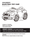
ELECTRIC TOY CAR
With remote control function
Products features may vary
from the picture above.
• Suitable for 37~96 Months
• Maximum user weight: 30kg
• Adult assembly required
OWNER'S MANUAL
with Assembly Instructions
Read and understand this entire manual before using!
Please keep this manual for future reference as it contains important
information.
Before first time use, charge the battery for at least 4-6 hours.
caution
WARNING
CHOKING HAZARD - Small parts.
Not suitable for children under 36
months.
Use the vehicle on generally level ground ONLY!
IMPORTANT
1WD
This label means the information or assembly for One Wheel Drive version ONLY!
2WD
This label means the information or assembly for Two Wheels Drive version ONLY!
H/L SPEED
This label means the information for High/Low Speed version ONLY!
WARNING!
FOR THE SAFETY OF YOUR CHILD, PLEASE READ ALL WARNINGS AND
ASSEMBLY/USE INSTRUCTIONS. KEEP THIS GUIDE FOR FUTURE REFERENCE.
• ADULT ASSEMBLY REQUIRED. The product contains small parts, which are for
adult assembly only. Keep children away when assembling.
• Always remove protective material and poly bags and dispose before assembly.
About Your New Vehicle
Thank you for your purchasing our products, we wants your child to enjoy this product for years to
come. Keep these points in mind as you read this guide:
Battery &
Fuse:
1WD
6V7AH x1(Fuse: 10A), 6V10AH x1 (Fuse:10A)
2WD
6V7AH x2 (Fuse: 5A and 13A), 12V7AH x1 (Fuse: 5A and 13A)
Load Capacity: Under 30KGS
Suitable age:
96 months
Average
Approximately
battery life:
300 times
Charge time: 8-12 Hours
VER:SMS-XX-EN-111212
VER:SMS-JE128-EN-RC-121105
VER:SMS-JE128-EN-121101
125 x 70 x 52 CM
Size of car:
Speed:
Charger:
1WD
Power way:
Charging type
3KM/H
2WD
3~5KM/H
Input: depend on local voltage
Output: DC 6V500mA or DC6V1A
or DC12V1A
Parts List
PART
NO.
1
2
3
4
5
6
7
PART NAME
Q’ty (pcs)
Vehiclebody
Gearbox
REMARKS
1
1WD
x1
2WD
x2
1WD
x1
2WD
x2
1WD
x3
2WD
x2
Bushing
1WD
x3
2pcsplacedonthefrontaxle,
1pcsplacedontherearaxle.
x2
Placedonthefrontaxle
Motorhood
2WD
1WD
2WD
x2
1WD
x4
2WD
x8
Drivingwheel
Normalwheel
Ø4x12flatheadscrew
x1
1pcslabeled“R”,1pcslabeled“L”
Placedonthesteeringwheel
8
9
10
11
12
13
14
15
16
17
18
19
20
21
Ø12washer
9
Ø10locknut
4
M5x16machinescrew
2
Sidesupport
2
Steeringcolumn
1
Rearaxle
1
Windshield
1
Viewmirror
2
Steeringwheel
1
M5x35machinescrew
1
Placedonthesteeringwheel
Ø5nut
1
2
1pcsplacedonthesteeringwheel,
Placedonthesteeringwheel
1pcsplacedonthesteeringcolumn.
Sparewheel
1
Seat
1
Charger
1
22
23
24
M5x20machinescrew
1
R/Cdriver
1
Remotecontroller
1
A
B
C
D
E
F
Ø4x12roundheadscrew
14
Ø4x16screw
2
Hubcap
5
Splitpin
2
1 pcs FOR SPARE
Ø10Washer
3
2
1 pcs FOR SPARE
Spanner
2
Placedonthevehiclebody
零
件
包
Parts Diagram
Tools Required
20
Screwdriver(not included)
10
10
Pliers(not included)
16
C
17
19
Spanner
18
15
21
A
7
14
6
24
1
13
3
2
4
C
9
5
8
8
C
9
8
18 B
23
22
12
NOTE: Some parts shown are
assembled on both sides of vehicle
11
A
D
E
Assembly Steps
• Your new vehicle requires adult assembly. Please set aside at least 40 minutes for assembly. Children
can be harmed by small parts, sharp edges and sharp points in the vehicle's unassembled state. Care should
be taken in unpacking and assembly of the vehicle. Children should not handle parts, or help in assembly of
the vehicle.
• Please identify all parts before assembly and save all packaging material until assembly is complete to
ensure that no parts are discarded.
• Assembly tool for need: screwdriver(provide for oneself) and spanner.
1
x6
Ø4x12 round
head screws
Side support
● Turn the vehicle body downside up.
● Fit the side support to the vehicle
body.
(HINT: If the side support does not
seem to fit, change the other one and
try again! )
● Insert six Ø4x12 round head screws
and tighten with a screwdriver.
● Repeat for the other side.
2
● Remove all the parts from the
rear axle.
● Slide a Ø12 washer onto the rear axle
from the longer end.
Rear axle
● Insert the rear axle through the hole in
vehicle body.
Rear axle
Ø12 Washer
● Remove all the parts from the rear
axle.
● Insert the rear axle through the hole in
the vehicle body.
Rear axle
2WD
Assembly Steps
Driving wheel
3
Spare wheel
Normal wheel
● Fit the gear box onto the rear
axle from the left side (Standing at the
rear of the vehicle body). And make the
motor on the gear box pass through the
hole in the vehicle body.
Gear box
Ø12
Washer
● Fit the driving wheel onto the rear
axle, keep it match with the gear box.
● Fit a Ø12 washer onto the rear axle.
Ø10
Locknut
Driving wheel
Rear axle
● Fit a Ø10 locknut to the end of the
rear axle.
● Slide the gear box (standing at back of vehicle body) onto the rear axle. “R” labeled gear box
should be fit to the “R” side of vehicle body; “L” labeled gear box should be fit to “L” side of
vehicle body.
● Slide the driving wheel onto rear axle, make it match with the gear box.
● Slide a Ø12 washer.
● Tighten the Ø10 locknut with a spanner.(Do not over tighten)
● Repeat this procedure to assemble the other driving wheel to the rear axle.
2WD
Hint: An extra spanner has been provided to hold the Ø10 locknut on the other side
of the front axle while tightening the locknut on the other side.
4
Normal wheel Ø12
Washer
● Remove the parts from the front axle.
● Fit a Ø12 washer onto the axle.
● Fit a bushing onto the axle.
Ø10
Locknut
● Fit a normal wheel onto the axle, make
the wheel match with the bushing.
● Fit a Ø12 washer onto the axle.
Ø12
Washer
Bushing
Front axle
● Tighten the Ø10 locknut with a spanner.
(Do not over tighten)
● Repeat for the other wheel(s).
Assembly Steps
● “Snap” a hubcap onto the center of
each wheel cover.
5
Hubcaps
6
6-1
6-2
BOTTOM VIEW
Ø12 washer
M5x20 machine
screw
R/C driver
Steering column
Ø10 washer
Steering
column Split pin
Split pin
Ø10
washer
R/C driver
Steering column
Direction
gear box
Ø5 nut
Steering column
6-1
●●Turn
Turnthe
thevehicle
vehiclebody
bodyon
onits
itsside.
side.
●●Remove
nutthe
from
the R/C
driver
screwdriver.
Slide a Øthe
10 screw
washerand
onto
steering
shaft
fromwith
theastraight
end(PIC 6-1).
Insertthe
thestraight
straightend
endofofsteering
steeringcolumn
shaft upupthrough
vehicle
●●Insert
throughthe
thehole
holeatinthe
thefront
R/Cofdriver,
thebody
holefrom
in the
bottom side,
in dash.body. Continue pushing the steering column to pass
direction
gearand
box out
andthrough
the holethe
in hole
the vehicle
through
the ofdash.
● Insertthe
thehole
bentinend
steering shaft through the hole in the front axle linkage, insert a Ø10
washer
onto
the
steering
and insert
a split
the hole column,
in the steering
bend the
● Line up the holes in the shaft
R/C driver
with the
holepin
in into
the steering
tightenshaft,
the M5x20
ends of split
pinand
back
a pairin of
6-2). with a screwdriver(PIC 6-1).
machine
screw
Ø5using
nut back
thepliers(PIC
same location
● Insert the bent end of steering column through the hole in the front axle linkage, insert a Ø10
washer onto the steering column and insert a split pin into the hole in the steering shaft, bend the
ends of split pin back using a pair of pliers(PIC 6-2).
Assembly Steps
7
Slots in the vehicle body
BOTTOM VIEW
Hubcap
Spare wheel
REAR VIEW
Ø4x16 round
head screws
● Insert the tabs in the spare wheel into the slots at the rear of the vehicle body,
● Insert two Ø4x16 round head screws through the vehicle body wall and into the spare wheel,
tighten with a screwdriver.
● “Snap” the hubcap into the wheel cover of spare wheel.
8
Windshield
Ø4x12 round
head screws
● Turn the vehicle body upright.
● Fit the tabs on the windshield into the
slots in the vehicle.
● Insert two Ø4x12 round head screws
and tighten with a screwdriver.
Assembly Steps
9
Steering wheel
M5x35
machine screw
Ø5 nut
End of steering
column
10
Motor connector
Vehicle connector
Fuse box
11
Ø4x12
flat head
screw
● Remove the M5x35 machine screw
and Ø5 nut from the steering wheel.
● Insert the steering wheel to the end of
the steering column.
● Insert the M5x35 machine screw
through the steering wheel and steering
column, and tighten the Ø5 nut back in
the same location.
● Plug the power connector into the
terminal on battery as shown.
● Plug the vehicle connector(s) into the
motor connector(s).
Power connector
● Fit the motor hood on the motor.
● Tighten four Ø4x12 flat head screws to
secure it.
x4
Motor hood
● Repeat for the other side.
2WD
Assembly Steps
● Insert the tabs at the back of the seat
into the slots in the vehicle body.
● Insert two M5x16 machine screws, and
tighten with a screwdriver.
12
M5x16
machine screw
Tabs at back of seat
Seat
13
View mirror
● Insert the view mirror into the hole in
the vehicle body and push until you hear
this click into place.
● Repeat for the other side.
IMPORTANT SUPPLEMENT TO INSTRUCTION MANUAL
GAP
After assembling any wheel to the axles, please check the gap
between the screw thread and the collapsible (refer to below
picture), if the gap is too big, please add two or three washers inside
the wheel, But after tightening the nut outside the wheel, please turn
the wheel by your finger to check if the wheel can run smoothly, this
is very important, because if the wheel can run smoothly, it is ok, but
if the nut press the wheel and the wheel can’t run smoothly, the
motor will be broken easily! Then you need to decrease one or two
washers to make sure the wheel can run smoothly!
How To Operate Your Vehicle
WARNING!
PREVENT INJURIES AND DEATHS:
• NEVER LEAVE CHILD UNATTENDED. DIRECT ADULT SUPERVISION IS REQUIRED.
Always keep child in view when child is in vehicle.
• This toy should be used with caution since skill is required to avoid falls or collisions causing
injury to the user or third parties.
• Protective equipment should be worn.
• Never use in roadways, near cars, on or near steep inclines or steps, swimming pools or
other bodies of water.
• Always wear shoes.
• Always sit on the seat.
• Not to be used in traffic.
• This toy is unsuitable for children under 37 months due to its maximum speed; Maximum
user weight is 30 kgs.
• This toy has no brake.
Must confirm before using that following work which is already finished:
• Important! Before using the vehicle for the first time, the battery needs to be charged for 4 to 6 hours, no
more than 10 hours. Only an adult can charge and recharge the battery.
• Check all the screws, cap nuts and protective coverings regularly and tighten as required. Check plastic
parts on a regular basis for cracks or broken pieces.
Rules for Safe Riding
READ THESE RULES ALOUD TO YOUR CHILD AND THEIR PLAYMATES AND MAKE SURE
THEY UNDERSTAND THEM!
• Keep Children within Safe Riding Areas:
- Never use in roadway, near motor vehicles, on lawn space, on or near steep inclines or steps,
swimming pools or other bodies of water;
• Use the toy only on flat surfaces. Such as inside your house, garden or playground.
• Never use in the dark. A child could encounter unexpected obstacles and have an accident. Operate the
vehicle only in the daytime or a well-lit area.
• It is not recommended to drive the vehicle on wet surfaces or on lopes of greater than 15 degrees.
• Do not use this vehicle outdoors when it is raining or snowing.
• Make sure you come to a complete stop before changing directions from forward to back.
• Please follow the correct weight and age limits allowed to drive this vehicle.
• It is prohibited to change the circuit or add other electric parts
• Inspect wires and connections of the vehicle periodically.
• In order to avoid accidents, please ensure the vehicle is safe before riding.
• Do not let any child touch the wheels or be near them when the car is moving .
• This vehicle has adjustable play seat belts. Please instruct children how to tie the safety belt before using,
guarantee the security.
How To Operate Your Vehicle
Use Operation A
Sound buttons Audio input
Digital voltmeter (OPTIONAL)
Forward-Reverse
switch
Volume knob
IMPORTANT!
Always stop vehicle
when changing the
speed or direction to
avoid damage the gears
and motor.
R/C-Pedal
Power
switch
switch
Foot pedal
H/L SPEED
Power switch
Use Operation B
Sound buttons Audio input
Digital voltmeter (OPTIONAL)
FORWARD
Forward-Reverse
1.Press the “Forward-backward switch” on the “Forward” position.
switch
2.Press the “Foot pedal”, the vehicle drives forward.
ADVANCED USE High speed Drive
Make sure your child
knows how to steer, how
to start and stop the
STOP
Volume knob
vehicle and knows the
High-Low
The vehicle will stop automatically, when your child’s foot remove from
the “Foot rules
pedal”.
for safe driving. The
speed
REVERSE
switch
vehicle can be driven at a
maximum of 3~5 km/h.
1.Press the “Forward-backward switch” on the “Backward” position.
R/C-Pedal
switch
2.Press the “Foot pedal”, the vehicle drives backward.
SOUNDS BUTTON
Foot pedal
Power switch
Press the buttons on the steering wheel for sound playing.
VOLUME
KNOB
FORWARD
1.Press
the “Forward-backward
switch”
on the “Forward”
position.
Turn
the knob
clockwise to increase
the volume;
Turn the knob
counterclockwise to decrease the
2.Press the “Foot pedal”, the vehicle drives forward.
volume.
STOP
BATTERY
CONDITION
(OPTIONAL)
The vehicle
will stop METER
automatically,
when your child’s foot remove from the “Foot pedal”.
REVERSE
The indicators will go out from right to left to indicate how much the battery remaining. When one red
1.Press only,
the “Forward-backward
switch” on the “Backward” position.
indicator
recharge the battery.
2.Press the “Foot pedal”, the vehicle drives backward.
SOUNDS BUTTON
Press the buttons on the dash and rear light bar for sound playing.
VOLUME KNOB
Turn the knob clockwise to increase the volume; Turn the knob counterclockwise to decrease the volume.
IMPORTANT!
HIGH/LOW SPEED SWITCH (OPTIONAL)
The switch operates the vehicle to move in low or high speed.
Always
stop vehicle(OPTIONAL)
when changing the speed or direction to avoid damage
DIGITAL VOLTMETER
page and
14. motor.
theSee
gears
HOW TO USE THE REMOTE CONTROLLER
ADULT OPERATING REQUIRED
LEFT JOY STICK
ON-OFF SWITCH
INDICATOR LIGHT
RIGHT JOY STICK
ASSEMBLY
1. Insert the antenna into the controller by tweak the antenna clockwisely;
2. Lift the battery compartment door on the back of the controller and insert two AA(LR6)
batteries.
NOTE: This product didn’t included the AA(LR6) batteries.
BATTERY INFORMATION
Batteries may leak fluids that can cause chemical burn injury or ruin your product. To avoid battery leakage:
● Do not mix old and new batteries.
● Do not mix different types of batteries: alkaline, standard (carbon-zinc) or rechargeable (nickel-cadmium).
Insert batteries as indicated inside the battery compartment.
● Remove batteries during long periods of non-use. Always remove exhausted batteries from the product.
Battery leakage and corrosion can damage this product. Dispose of batteries safely.
● Do not dispose of batteries in a fire. The batteries may explode or leak.
● Never short circuit the battery terminals.
● Non-rechargeable batteries are not to be recharged.
● Use only batteries of the same or equivalent type as recommended.
● If removable rechargeable batteries are used, the are only to be charged under adult supervision.
● Remove rechargeable batteries from the product before charging.
● Batter chargers used with toys must be examined regularly for damage to the cord, plug, enclosure and
other parts. In the event that such damage is found, the toy must not be used with the battery charger until
the damage has been repaired.
OPERATION
1. Press the CONVERSION SWITCH on the vehicle to the “Remote control” position.
2. Press the ON-OFF SWITCH on the remote controller to the “ON” position, the indicator light
will be lighting.
3. Push the LEFT JOY STICK to the front, the vehicle goes forward, pull the LEFT JOY STICK
to the back, the vehicle goes backward.
4. Push the RIGHT JOY STICK to the left, the vehicle turn left, push the RIGHT JOY STICK to
the right, the vehicle turns right.
Charging Your Vehicle
ONLY AN ADULT CAN CHARGE AND RECHARGE THE BATTERY!
WARNING!
• PREVENT FIRE AND ELECTRIC SHOCK:
- Use the only rechargeable battery and charger supplied with your vehicle. NEVER substitute the battery
or the charger with another brand. Using another battery or charger my cause a fire or explosion.
- Do not use the battery or charger for any other product. Overheating, fire or explosion could occur.
- NEVER modify the electric circuit system. Tampering with the electric system may cause a shock, fire or
explosion or my permanently damage the system.
- Do not allow direct contact between battery terminals. Fire or explosion can occur.
- Do not allow any type of liquid on the battery or its components.
- Explosive gasses are created during charging. Do not charge near heat or flammable materials. Charge
the battery in a well-ventilated area ONLY.
- NEVER pick up the battery by the wires or charger. Damage can occur to the battery and may cause a
fire. Pick up the battery by the case ONLY.
- Charge the battery in a dry area ONLY.
• Battery posts, terminals and related accessories contain lead and lead compounds, chemicals
known to the State of California to cause cancer and reproductive harm. Wash hands after
handling.
• Do not open the battery. Battery contains lead acid and other materials that are toxic and
corrosive.
• Do not open the charger. Exposed wiring and circuitry inside case may cause electric shock.•
Only adults may handle or charge the battery. NEVER allow child to handle or charge the
battery. Battery is heavy and contains lead acid (electrolyte).
• Do not drop the battery. Permanent damage to the battery could occur or cause serious injury.
• Before charging the battery, check for wear or damage to the battery, charger, its supply cord
and the connectors. DO NOT charge the battery if any damage to parts has occurred.
• Do not allow the battery to drain completely. Recharge the battery after each use or once a
month if not used regularly.
• Do not charge battery upside down.
• Always secure the battery with the bracket. Battery can fall out and injure a child if vehicle tips
over.
• The charging input socket is at the right side of the spare wheel.
• The POWER SWITCH must be turned in OFF position when charging.
• Before the first use, you should charge the battery for 4-6 hours. Do not recharge the battery for more than
10 hours to avoid overheating the charger.
• When the vehicle begins to run slowly, recharge the battery.
• After each use or once a month minimum recharge time as 8 to 12 hours, less than 20 hours at most.
Charging Your Vehicle
• According the table to decide whether to charge the battery:
BATTERY
6V4Ahx1, 6V7Ahx1
6V10Ahx1
6V7Ahx2, 6V10Ahx2
12V7Ahx1, 12V10Ahx1
MAGNITUDE OF VOLTAGE
≥ 6.6
BATTERY STATE
The battery is full.
6.5~6.3
The vehicle can wrok normally.
≤ 6.2
STOP operating the vehicle, the battery needs to charge.
≥ 13.2
The battery is full.
13.1~12.6
The vehicle can wrok normally.
≤ 12.5
STOP operating the vehicle, the battery needs to charge.
1
1
1. Open the cover of the socket (the socket is at the right side of the spare wheel)
2. Plug the charger port into the input socket.
3. Plug the charger plug into a wall outlet. The battery will begin charging.
WARNING!
This product with CHARGING PROTECTION: When charging, all the functions will be cut off!
Troubleshooting Guide
■ PROBLEM: The vehicle does not run
PROBLEM CAUSE: The battery may low on power.
After each use, or once a month minimum, charge the battery for a full 10 hours. Do not leave the
battery on the charger for more than 20 hours.
POSSIBLE CAUSE: Thermal fuse has tripped.
The vehicle is equipped with a self-resetting fuse. When the vehicle is overloaded or operated
incorrectly; the self-resetting fuse will be cut off for 5-20seconds before becoming operational
again. The self-resetting fuse is under the seat (Refer to the picture.)
Fuse
To avoid the fuse cut off the power, follow these
guidelines:
DO NOT overload the vehicle, Maximum weight
allowed :30kg
DO NOT tow anything behind the vehicle.
DO NOT drive up steep slopes.
DO NOT drive into fixed objects, which may cause the
wheels to spin, causing the motor to overheat.
DO NOT drive in very hot weather, components may
overheat.
DO NOT tamper with the electric system, Doing so may
create a short circuit, causing the fuse to trip.
Battery
POSSIBLE CAUSE: Wheel nuts are loose.
If the nuts are not tight, the wheels will not engage the forward gears. Tighten the nut with the nut wrench.
POSSIBLE CAUSE: Battery connector or wires are loose.
Make Sure the battery connectors are firmly plugged in to each other.
POSSIBLE CAUSE: Battery is dead.
Have you properly maintained the battery according to the directions? Is the battery old? Your
battery may need to be replaced.
POSSIBLE CAUSE: Electric system is damaged.
Water may have corroded the system, or loose dirt, gravel or sand might have jammed the switch.
POSSIBLE CAUSE: Motor is damaged.
The motor needs professional repair.
■ PROBLEM: The battery will not recharge.
POSSIBLE CAUSE: Battery connector or adapter connector is loose.
Make sure the battery connector and adapter connector are firmly plugged together.
POSSIBLE CAUSE: Charger is not plugged in.
Make sure the charger is plugged into the wall outlet and the power flow to the outlet is on.
POSSIBLE CAUSE: Charger is not working.
Is the charger warm while charging? If not, the charger may be broken and may need to be replaced.
Troubleshooting Guide
■ PROBLEM: The vehicle does not run very long.
POSSIBLE CAUSE: Battery may be undercharged.
You may not be charging the battery long enough. After each use, or once a month minimum, charge the
battery for 8 to 10 hours. Do not leave the battery on the charger for more than 20 hours.
POSSIBLE CAUSE: Battery is old.
The battery will eventually lose the ability to hold a charge. Depending on the amount of use, and
varying conditions, the battery should operate for one to three years. Replace the battery with a
new one.
■ PROBLEM: Battery buzzes or gurgles when charging.
This is normal and not a cause for concern. It may also be silent when charging, which is also normal.
■ PROBLEM: Charger feels warm when recharging battery.
This is normal and not a cause for concern.
Maintaining Your Vehicle
• It is parents' responsibility to check main parts of the toy before using, Must regularly examine for potential
hazard, such as the battery, charge,cable or cord, plug, screws are fastening enclosure of other parts and
that in the event of such damage, the toy must not be until that damage had been properly removed.
• Make sure the plastic parts of the vehicle are not cracked or broken.
• Occasionally use a lightweight oil to lubricate moving parts such as wheels.
• Park the vehicle indoors or cover it with a tarp to protect it from wet weather.
• Keep the vehicle away from sources of heat, such as stoves and heaters. Plastic parts may melt.
• Recharge the battery after each use. Only an adult can handle the battery. Recharge the battery at least
once a month when the vehicle Raider is not being used.
• Do not wash the vehicle with a hose. Do not wash the vehicle with soap and water. Do not drive the vehicle
in rainy or snowy weather. Water will damage the motor, electric system and battery.
• Clean the vehicle with a soft, dry cloth. To restore shine to plastic parts, use a non-wax furniture polish. Do
not use car wax. Do not use abrasive cleaners.
• Do not drive the vehicle in loose dirt, sand or fine gravel which could damage moving parts, motors or the
electric system.
• When not using, all the electrical source should be turn off. Turn off the power switch and disconnect the
battery connection.
Disposal Of Battery
Disposal Of Batter y
● Your sealed lead-acid battery must be recycled or disposed of in an environmentally
sound manner.
● Do not dispose of your lead-acid battery in a fire. The battery may explode or leak.
● Do not dispose of a lead-acid battery in your regular, household trash. The incineration,
land filling or mixing of sealed lead-acid batteries with household trash is prohibited by
law.
● Return an exhausted battery to your local approved lead-acid battery recycle, such as a
local seller of automotive batteries.
● Contact your local waste management officials for other information regarding the
environmentally sound recycling and disposal of lead-acid batteries.
Our products are suitable for
ASTM F963; GB6675; EN71 and EN62115 standard.