1
Caution: This document contains mixed page sizes (8.5 x 11 or 11 x
17), which may affect printing. Please adjust your printer settings
according to the size of each page you wish to print.
4
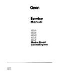
Service
f
DJBA
DJB
DJC
DJE
Diesel Engines
967-0751
3-88
Printedin USA.
Redistribution or publication of this document,
by any means, is strictly prohibited.
,
Safety Precautions
DO NOT smoke or use an open flame in the vicinity of
the engine or fuel tank. Internal combustion .engine
fuels are highly flammable.
It is recommended that you read your engine manual and
become thoroughly acquainted with your equipment before you start the engine.
Fuel lines must be of steel piping, adequately secured.
and free from leaks. PiDina at the enaine should be
approved flexible me. PO nor use copper piping ror
flexible lines as copper will work harden and become
brittle enough to break.
b
.
E
Be sure all fuel supplies have a positive shutoff valve.
Fuels, electrical equipment, batteries, exhaust gases and
moving parts present potential hazards that could result in
serious, personal injury. Take care in following these
recommended procedures. '
Exhrust Systom
Exhaust products of any internal combustion engine
are toxic andcan cause injury, or death if inhaled. All
engine applications, especiallythose within a confined
area, should be equipped with an exhaust system to
discharge gases to the outside atmosphere.
Do not use exhaust gases to heat a.compartment.
S8fOty COdW
0
0
All local, state and federal codes should be consulted
and complied with.
This engine is not designed or intended for use 'in
aircraft. Any such use is at the owner's sole risk. .
'
General
Provide appropriate fire extinguishers and install them
in convenientlocations. Use an extinguisherratedABC
by NFPA.
Make sure that all fasteners on the engine are secure
and accurately torqued. Keep guards in position over
fans, driving belts, etc.
If It is necessary to makeadjustmentswhile theengine is
running, use extreme caution when close to hot exhausts, moving parts, etc.
Protect Against Movlng Parts
Do not wear loose clothing in the vicinity of moving
parts, such as PTO shafts, flywheels, tilowers, couplings, fans, belts, etc.
Keep your hands away from moving parts.
Batted08
0
Before starting work on the engine. disconnect batteries to prevent inadvertentstarting of the engine.
DO NOT SMOKE while servicing batteries. Lead acid
batteriesgive off a highly explosivehydrogengas which
can be ignited by flame, electricalarcing or by smoking.
Verify batterypolaritybeforeconnecting battery cables.
Connect negative cable last.
FwI Systom
0
DO NOT fill fuel tanks while engine is runnirlg.
Make sure that your exhaust system is free of leaks.
Ensure that exhaust manifolds are secure and are not
warped by bolts unevenly torqued.
Exhrust Gas is Dordlyi
Exhaust gases contain carbon monoxide, a poisonous gas
that might cause unconsciousness and death. It is an
odorless and colorless gas formed during combustion of
hydrocarbon fuels. Symptoms of carbon monoxide poisoning are:
Dizziness
.Vomiting
Headache
0 Muscular Twitching
0 Throbbing in Temples
Weakness and Sleepiness
c
If you experience any of these symptoms, get out into fresh
air immediately, shut down the unit and do not use until it
has been inspected.
The best protection against carbon monoxide inhalation is
proper installationand regular, frequent inspections of the
complete exhaust system. If you notice a change in the
sound or appearance of exhaust system, shut the unit down
immediatelyand have It inspectedand repairedat once by a
competent mechanic.
'Cooling Systom .
0 Coolants under pressure have a higher boiling point
than water. DO NOT open a radiator pressure cap when
coolant temperature is above 212OF (100OC) or while
engine is running.
Kwp the Unlt and SurroundingAroa Clem
'Make sure that oily rags are not left on or'near the
engine.
0
0
Remove all unnecessary grease and oil from the unit.
Accumulated grease and oil can cause overheatingand
subsequent engine damage and present a potential fire
hazard.
Redistribution or publication of this document,
by any means, is strictly prohibited.
. E4
b
Y
Table of Contents
c
TITLE
PAGE
General Information ..................................................
2
Specifications .......................................
.............. 3
4
Dimensions and Clearances ...........................................
Assembly Torques and Special Tools ..................................
6
Engine Troubleshooting...............................................
7
Service and Maintenance ..............................................
8
Exhaust System .....................................................
14
Cooling System ......................................................
16
Fuel System .........................................................
18
Governor System ....................................................
38
Oil System ..........................................................
40
Starting System ......................................................
45
51
Flywheel Alternator ..................................................
EngineDisassembly .................................................
55
Special Equipment ...................................................
67
68
Control System ......................................................
Wiring Diagram ...........' ...........................................
69
..-.
I
WARNING
INCORRECT SERVICE OR REPLACEMENT OF PARTS MIGHT RESULT IN
SEVERE PERSONAL INJURY AND/OR EQUIPMENT DAMAGE SERVICE
PERSONNEL MUST BE QUALIFIED TO PERFORM ELECTRICAL AND/OR
MECHANlCAL SERVICE
.
.
I
Redistribution or publication of this document,
by any means, is strictly prohibited.
General Information
INTRODUCTION
ENGINE MODEL REFERENCE
This manual deals with specific mechanical and electrical information needed by engine mechanics for
troubleshooting, servicing, repairing, or overhauling
the engine.
IUentlTy your moael DY reTerririy LO L I I ~IVIWLKL
aiiu
SPEC (specification) NO. as shown on the unit
nameplate. Always use this number and the engine
serial number when making reference to your engine.
Use the table of contents for a quick reference to the
separate engine system sections.
How to interpret MODEL and SPEC NO.
Use the separate Parts Catalogs available at the
dealer level, for parts identification and for establishing their proper location on assemblies.'
1
2
3 4
The troubleshooting guide is provided as a quick
reference for locating and correcting engine trouble.
The illustrations and procedures presented in each
section apply t o the engines listed on the cover. The
flywheel end of the engine is the front end, so right
and left sides are determined by viewing the engine
from the front.
1. Factory code for general identification purposes.
2. Specific Type:
MS ELECTRlC starting .with stub shaft.
3. Factory code for optional equipment supplied.
4. Specification (Spec Letter) advances with factory
production modification.
-
The disassembly section contains major,. overhaul
procedures for step by step .removal, disassembly,
inspection, repair and assembly of the engine
components.
If a major repair or an overhaul is necessary, a competent mechanic should either do the job or supervise
and check the work of the mechanic assigned to do
the job to ensure that all dimensions, clearances and
torque values are within the specified tolerances.
The wiring diagram on the last page of the manual
shows how the electrical components are interconnected.
A parts catalog (available at the dealer level) contains
detailed exploded views of each assembly and the
individual piece part numbers and their proper names
for ordering replacement parts.
Use only Genuine Onan replacement parts to ensure
quality and the best possible repair and overhaul
results. When ordering parts, always use the complete Model and Spec number as well as the Serial
number shown on the nameplate.
2
Redistribution or publication of this document,
by any means, is strictly prohibited.
c
;
Specifications
All dimensions in U.S. customary units of measure (metric in parentheses) unless otherwise specified.
SPECIFICATION
UNIT OF
MEASURE
DJB
Number of Cylinders
Diesel Fuel
Bore
2
in
(mm)
in
(mm)
cuin
(litre)
Stroke
Displacement
Compression Ratio
Firing Order
Crankshaft Rotation
(viewed from flywheel)
Governor
Valve Clearance
Intake
Oil Filter
Crankcase Capacity
with filter change
.
2
ASTM2-D
3.25
(82.55)
3.625
(92.08)
60
(0.98)
19 to 1
ASTM2-D
3.25
. (82.55)
3.625
(92.08)
60
(0.98)
19 to 1
1-2
DJE
DJC
2
4
ASTM2-D
3.5
(88.90)
3.625
(92.08)
ASTM2- D
3.25
(82.55)
3.625
(92.08)
120
(1.97)
19 to 1
1-2-4-3
70
(1-2)
19 to 1
1-2
Clockwise
Clockwise
Clockwise
Adjustable Mechanical
Begin Spec D
Clockwise
.
Spec A-C
in
(mm)
in
(mm)
Exhaust
SERIES
DJBA
Qt
(I itre)
0.004
0.009
(0.23)
(0.10)
0.009
0.004
(0.10)
(0.23)
Full Flow
3.5
(3.3)
0.009
(0.23)
0.007
(0.18)
Full Flow
3.5
(3.3)
0.010
(0.25)
0.007
(0.1 8)
Full Flow
3.5
(3.3)
0.009
(0.23)
0.007
(0.1 8
Full Flow
6.5
(6.2)
NOTE: DJB and DJBA engines differ only in crankshaft, injection pump,
camshaft, and their associated piece parts. DJB is even-firing (pistons
move up and down together); DJBA is odd-firing (one piston moves up
as the other moves down.
3
Redistribution or publication of this document,
by any means, is strictly prohibited.
Dimensions and Clearances
.
All clearances given at room temperature of 70" F (21O C)
All dimensions in inches (millimeters in parentheses) unless otherwise specified
.
CAMSHAFT
Bearing Journal Diameter. Front .........................................
2.2500-2.2505 (57.150-57.1 63)
I LJUUI LJUC
[U 1 .ac r ~ 1-.acruJ
~
Bearing Journai uiaiiieiei. ueii~ei\ U J ~ )
1.1875-1.1880 (30.163-30.175)
Bearing Journal Diameter. Rear
Bearing Clearance Limit (Original)
.0015.. 0030 (.038-.076)
Bearing Clearance Limit (Replacement)..........................................
.0012-. 0049 (.030-.123)
End Play ............................................................................
.007-. 039 (0.2-1.0)
Cam Tappet Diameter (Prior to Spec P) ......................................
.7475-. 7480 (18.987-18.999)
Cam Tappet Hole Diameter (Prior to Spec P) ..................................
.7507-. 7515 (19.068-19.088)
Cam Tappet Diameter (Begin Spec P) .......................................
.8725.. 8730 (22.162-22.174)
Cam Tappet Hole Diameter (Begin Spec P) ..................................
.8755-. 8765 (22.238-22.263)
CONNECTING RODS
2.1871-2.1876 (55.5523-55.5650)
Large Bore Diameter ..................................................
Small Bore Diameter
1.043-1.045 (26.4922-26.543)
Large Bearing Bore to Small Bearing Bore
(Center-to-Center)
5.998-6.002 (152.3492-152.4508)
Connecting Rod End Play
.002-. 016 (.05-.41)
CYLINDER
Bore Honed Diameter
3.2495-3.2505 (82.537-82.563)
3.4995-3.5005 (88.887-88.913)
Bore Honed Diameter (DJE) ...............................................
Maximum Allowable Taper .................................................................
0.005 (0.127)
Maximum Allowable Out-Of-Round ..........................................................
0.001 (0.025)
..................................
..........................................
..............................................
......................................................
..................................................
............................................................
......................................................
CRANKSHAFT
Main Bearing Journal Diameter .............................................
2.2437-2.2445 (56.99-57.01)
Main Bearing Journal Diameter (DJC)
2.2427-2.2435 (56.965-56.985)
Center Main Bearing Clearance (DJC)
.0024.. 0052 (.061-.132)
.0030.. 0043 (.076-.109)
Front and Rear Main Bearing Clearance (Original) (DJC)
Front and Rear Main Bearing Clearance (Replacement) (DJC)
.0024-. 0062 (.06-.16)
Main Bearing Clearance (Original)
.'... .002.. 0033 (.051-.084)
Main Bearing Clearance (Replacement) ............................................
.0014.. 0052 (.04-.13)
Connecting Rod Journal Diameter ........................................
2.0597-2.0605 (52.316-52.337)
Rod Bearing Clearance
.001.. 0033 (.025-.084)
End Play .........................................................................
.010-.015 (.254-.381)
PISTONS AND RINGS
Clearance in Cylinder
Measure 90" to pin. just below oil ring
(Prior to Spec P) .............................................................
.0050.. 0070 (.127-.178)
(Begin Spec P) ...............................................................
.0055-.
0075 (.140-.191)
Ring Groove Width
TOP .......................................................................
.0970-. 0980 (2.464-2.489)
No.2 ......................................................................
-0965-.0975 (2.451-2.477)
No. 3 ......................................................................
.0965.. 0975 (2.451-2.477)
NO.4 ......................................................................
.1880.. 1897 (4.775-4.818)
.010-. 020 (.25-51)
Ring Gap ...........................................................................
PISTON PIN
Clearance in Piston ...................................................................
Thumb Push Fit
Connecting Rod Bushing Clearance .............................................
-0002-.0007 (-005-.018)
....................................
...........................................
.........................
.......................
............................................
.
..........................................................
4
Redistribution or publication of this document,
by any means, is strictly prohibited.
STARTING MOTOR (Prestolite)
Rotation ...........................................................................
Pinion Clearance to Pinion Stop (Solenoid Plunger Bottomed) .......
....
Armature End Play .........
.. . ..... ..... . . ..
... .
..... . .
..
...... .....
. .. .... .......... . ......
Counterclockwise
-070--120
(1-78-3.05)
.005--030
(-030-.760)
VALVE-INTAKE
Stem Diameter (Stem is tapered)
...
.......... ...
.
. ... . ....
-3401-.3411 (8.639-8.664)
**Center
**Face
.. . . ... . .
. . .. .....
.3386--3396
(8.601-8.626)
Valve Face .......................................................................................
44'
Guide Clearance
.. ....
. .. . . . ... ...
.0015-.003(-038-.076)
VALVE-EXHAUST
Stem Diameter . . .. ..
. .... ................... .
-3405--3415
(8.649-8.674)
Guide Clearance .
.. . . .. .
.0030-.0050(.076-.127)
Valve Face .......................................................................................
45"
VALVEGUIDE
Length ..............................................................................
1.7812(45.2424)
. . .. ..
.4690-.4695(11.9126-11.9253)
Outside Diameter
Inside Diameter (after reaming)
.....
.
.
. ..
.
.3445-.3455(8.750-8.776)
Exhaust
Intake .....................................................................
.3425-.3435(8.700-8.725)
Cylinder Block Bore Diameter..
.... ....... ............ ....... ..... .467-.468(11.8618-11.8872)
VALVE SEATS
Valve Seat Bore (Diameter)
Intake
. . . .. .. . .
.
..
. 1.547-1548 (39.29-39.32)
.
. ........ . . . ... , . 1.361-1.362(34.570-34.595)
Exhaust ... .. . ..
Depth (from Cylinder Head Face)
.
. . ... ... ... . . .. . .433-.439(10.99-11.15)
Seat Outside Diameter
..... .. . ................. ... 1.364-1.365(34.6456-34.6710)
Exhaust . . . ..
Intake ... . ...
.. ....:'. ............ ........... .... .... 1 S50-1.551 (39.37-39.39)
Seatwidth .......................................................................
.047-.062(1.19-1.57)
Angle.. .
..... ... ........ .. ... .... ... ..... ......... .... . . . .... .. 45"
Available Insert Oversizes . .
. . . . ....... ........... . . .. . .......
. .... .002(.0508)
.......... .....
.. ............. ..... . . . .....
............ ... . . ... . ....................... .. . . .....
... . ................. .. ... . .. .. .. .............
t
... .. ............... . ..
.. .... ...
........... .. . .........................................
.
........ ... . .....................................
........ ........ ................ ...... ... .......... .....
.. . . . ..
.
. .
.... ... . . . .... ...... ...... . ... ........... .... . ... ... . ...
.
. . . . . . . . . . .. . .. . .. . . .. . . . . .
... .. . . .. . .
.. . . ... .. .. ... .. .... .. .... ..
. . . . . . . . . . . . . .. . . . . . . .. .
. ..
.
. ... . ...... ....
. ..
. . ...
.. .... ............. ..
... . . . .
. ..
.. . .. . . . . . . . . .
.. . .
. ..... .
.
.005(.127)
.010(.254)
.025(.635)
VALVE SPRINGS
Load-Valve Closed . .. .
Load-Valve Open (Prior to Spec P)
Load-Valve Open (Begin Spec P).
. .. .. . ... .............. .. ... ......................... ....
. ..... ........ ... ........... ................ ..
............. .. .............. ................ ..
4
*
45-49Ib (200-218N*)
83-93Ib '(369-414N*)
87-97Ib (388-432N*)
* N. Base unit, Newtons. Unit of force.
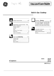
** Measure intake valve stem at points indicated.
Valve Stem Diameter
(Intake)
2.96 in
1.18 in
5
Redistribution or publication of this document,
by any means, is strictly prohibited.
Assembly Torques
TORQUE SPECIFICATIONS
Center main bolt (4 cylinder).
Connecting rod bolt., .
Rocker-Box cover..
Cylinder head bolt
,
The assembly torques given here will assure proper
tightness without danger of stripping threads. If a
torque wrench is not available, be careful not to strip
threads. Use reasonable force only and a wrench of
normal length.
Ft.-Lb.
Nom
. ... 97-102 (131-138)
.......... 27-29 (37-39)
.. .. ...... ... 8-10 (11-14)
(60-62)
.
-. .. .. .. ...... 44-46
Q-I
r;*
1.1 R-3l-l\
-. ...-.-. - - .--..-.
Flywheel mounting screw.. . ... .. 65-70 (88-95)
Hub to flywheel screws
(4 cylinder) ......,.... ... ... .. 17-21 (23-28)
Fuel pump mounting screws .. . . . 15-20 (20-27)
Gear case cover.. .. ... . .. ... .. . . 15-20 (20-27)
Glow Plug . ... .. . .. .. . . .. ... ... . 10-15 (18-20)
Injection nozzle mounting
screws .. ... . .. ..... . .. ... . .. . 20-21 (27-28)
Injection pump mounting
screws .. .. . .. .... . . .. . . . ... .. 15-16 (20-22)
Intake manifold . . . .. . . .. . . . . .. .. 13-15 (18-20)
Oil base mounting screws . . . .. .. 45-50 (61-68)
Oil filter . . . . . . .. .. . Hand tight plus 1/4 to 1/2 turn
Oil pump mounting screws .... .. 15-20 (20-27)
Rear bearing plate.. .. .. . .. . .. . . . 40-45 (54-61)
Rocker arm nut . .. . .. ... .. .... .. 4-IO** (5-13)
Rocker arm stud . . .. . . . .. ... .. . . 35-40 (47-54)
n-.
Specially designed place bolts do not require a lockwasher or gasket. Check all studs, nuts and screws
often and tighten as needed to keep them from working loose.
-1-
-_.-A
-.-:.C-i
A
&
..,
1
- Exhaust nuts must be tightened evenly.
** This torque is due to friction between the threads only and
locks the nuts in place. Use the rocker arm nut to adjust valve
lash.
-
Special Tools
h
Driver, Center Camshaft Bearing
(4 Cyl.)
.
. .
Driver, Combination Main and Cam
Reamer, Ridge.
. .. . ..
.
Valve Guide Remover and Driver
.. .
Diesel Nozzle Tester .
.
Diesel Pintle Nozzle Cleaning Tool Set
(Includes Injection Nozzle Centering
Tool)
... .
.
. ...
These tools are available from ONAN to aid service and
repair work.
. .......... . .. .......
. . . . .. . . . . . ..
....................
........
....... .....
Driver, Valve Seat
..
Oil Seal Guide and Driver..
.
Valve Seat Remover.
Replacement Blades for 420-0272
Crankshaft Gear Pulling Ring
.... ...... ......... .. .. . . ...
.. ... ..
... . .. ..... .......
.. . .. .
. . . . . . . . . . .. . . . .. .
420-0270 .
420-0456
420-031 1
420-0274
420-0409
.. ..
6
..... ...... . .... . . .
420-0254
420-0326
420-0260
420-0300
420-01 84
420-0208
Redistribution or publication of this document,
by any means, is strictly prohibited.
*
Engine Troubleshooting
Redistribution or publication of this document,
by any means, is strictly prohibited.
Service and Maintenance
PR E-STARTI NG
Recommended Fuel
Use ASTM 2-D or 1-D fuel with a minimum Cetane
number of 45*. Number 2 diesel fuel gives the best
economy for most operating conditions; however,
Preparations for the initial and each additional starting operation should include careful checks of the oil,
fuel, cooling, and electrical systems.
--- -- .a.n-r.
- . . .a. .
4
Before engine is put in operation, check all components for mechanical security. If an abnormal condition, defective part, or operating difficulty is detected,
repair or service as required. The engine should be
kept free of dust, dirt, and spilled oil or fuel. Be sure
proper operating procedure is followed.
n +..-I
-
A.
-
+L.. 4~1,-.,.,i,.,-,
-
onnAi+innc.
1. When ambient temperatures are below 32" F
(0" C);
2. During long periods of light engine load; or no
load.
*NOTE: Fuels with Cetane numbers higher than 45 may be needed
in higher altitudes or when extremely low ambient temperatures
are encountered to prevent misfires.
Crankcase Oil
Multi-grade oils (such as 5W-30) are recommended for
service in ambient temperatures of 32°F and colder. On
Onan J Diesel engines, SAE 15W-40 or 20W-40 oils
(CD/SEService Designation)may be used in an ambient
temperaturerangeof 15"F(-1OoC)through 9O0F(32"C).
Refer to the oil chart below for recommended viscosity
grades at various temperature ambients.
Use low sulfur content fuel having a pour point
(ability to filter) of at least 10°F below the lowest
expected temperature. Keep the fuel clean and protected from adverse weather. Leave some room for
expansion when filling the fuel tank.
l3iEE2
Due to the precise tolerances ofdiesel injection systems, it is extremely
important the fuel be kept clean. Dirt in the system
can cause severe damage to both the injection pump
and the injection nozzles.
WORK TRANSFER PUMP
PRIMING LEVER UNTIL
FUEL FLOWS FROM
RETURN LINE FITTING
OF INJECTION PUMP.
I
Useoil with an API classification of CD/SE (ali viscosity grades) or CC/SE (grades 1OW-30, 1OW-40, or
5W-30 only).
When adding oil between oil changes, it is preferable
to use the same brand, as various brands of oil may
not be compatible. Refer to Maintenance Schedule
for recommended oil change intervals and procedures.
FIGURE 1. BLEED FUEL SYSTEM
Crankcase pressure could blow out
hot oil and cause serious burns. Do
NOT check oil while the engine is operating.
if the camshaft pump lobe is up, crank engine one revolution to
permit hand priming. When finished, return priming lever inward
(disengaged position) to permit normal pump operation.
8
Redistribution or publication of this document,
by any means, is strictly prohibited.
1'
Bleeding Fuel System
steps 1 & 2-Absence of blue exhaust smoke during cranking indicates no fuel being deliveredDetermine cause.
4. In extreme cold it may be necessary to maintain
preheating up to 2 minutes afterthe enginestarts
to obtain firing or to smooth out all cylinders,
especially at no load or light loads.
Bleed air from fuel system asfollows: Disconnect fuel
return line, Figure 1. Operate hand priming lever on
fuel transfer pump until fuel flowing from fuel return
line is free of air bubbles. Then reconnect the fuel
return line.
PRE-HEATING AND STARTING
Preheating for 60 seconds is recommended on all
DJ-Series Diesels at 55°F (13°C)or lower, and 30
seconds for temperatures above 55°F (13°C).Refer
to Onan Dieselstarting Guide, for additional starting
guidelines.
Do not exceed the one minute
preheat periods to prevent heafer burn out and conserwe the battery. Longer
preheating time prior to cranking the engine can
ruin the manifold heaterandglowplugs because
there is no incoming air flow to cool them. Additional operation of the preheaters for a few
seconds during cranking in cold weather may
help to preheat the incoming combustion airand
prevent misfires as the engine starts running.
Inhalation of exhaust gases might
EiE!
result in serious personal injury or
death. Be sure deadly exhaust gas is piped outside
and away from windows, doors, or other inlets to
building.
5. Verify that oil pressure gauge reads at least 20 psi
i
Use of ether as a starting aid might
cause an explosion resulting in
severe personal injury and engine daniage. Do not
use ether as a starting aid; heat or compression or
heaf from the glow plugs may cause a sudden ignition
of the ether vapor.
after engine reaches speed (pressure relief valve
is not adjustable).
Do not apply overwoltage to the
starting circuit at any time.
Overvoltage will desfroy the glow plugs and air
heater. If it becomes necessary to use an additional source of power to start the set, use a 12
volt battery connected in parallel.
1. Engage PREHEAT switch for the time period
recommended below:
30 seconds if above 55" F (13°C)
60 seconds if below 55" F (13°C)
2. Engage START switch while continuing preheat.
Hold until engine comes up to speed.
3. If engine fails to start in 15-20 seconds, repeat
STOPPING
1. Push fuel solenoid switch to Stop position.
2. Releaseswitch when set stops. If stop circuit fails,
close fuel valve.
ONAN DIESEL STARTING GUIDE
INDUSTRIAL ENGINES
-
BEFORE STARTING:
I
~
CHECK FUEL SUPPLY.
BE SURE SHUTOFF VALVES ARE OPEN.
I
PRIME FUEL SYSTEM IF: FUEL FILTERS WERE DRAINED OR CHANGED.
SYSTEM WAS JUST INSTALLED. FUEL TANK RAN DRY.
TO PRIME FUEL SYSTEM:
MOVE PRIMING LEVER UP
AND DOWN UNTIL FUEL
FLOWS STEADILY FROM
RETURN LINE IDISCONNECTED).
I
3./INJECTION
FUEL TRANSFER
PUMP
PUMP
-.J-
PRIMING LEVER
FUEL FILTERS
FUEL RETURN LINE
30 SECONDS IF ABOVE 55 F (13 C):
60 SECONDS IF BELOW 55 F ( 1 3 C).
I
ENGAGE FUEL SOLENOID SWITCH IF SO EQUIPPED
I
ENGAGE START SWITCH WHILE CONTINUING PREHEAT
I
I
I
I
IF ENGINE FIRES BUT DOES NOTSTART. REPEATABOVEPROCEDURES. INCLUDING
PREMEAT. LIMIT CRANKING TO 15 TO 20 SECONDS TO CONSERVE BATTERY. IF
ENGINE STILL DOES NOTSTART. SEE"IF ENGINE FAILS TO START" INFORMATION.
9
Redistribution or publication of this document,
by any means, is strictly prohibited.
IF ENGINE FAILS TO START:
IMPORTANT!
KEEP ENTIRE FUEL SYSTEM CLEAN AND FREE FROM WATER
DIESEL INJECTION PUMPS WILL FAIL IF SYSTEM CLEANLINESS IS NEGLECTED
INJECTION PUMPS AND NOZZLES ARE NOT FIELD REPAIRABLE
WHEN TROUBLESHOOTING. CHECK ALL OTHER COMPONENTS FIRST
TEMPERATURES BELOW 32 F ( 0 C):
-.
.
.
-..-----
-- ..--
..a-
r_..C"
CTIDT,.,P.
4,n
--
I
-
OBSERVE ENGINE EXHAUST "SMOKE SIGNALS
- 7
-
I
I
USE NUMBER 1 DIESEL FUEL. USE CORRECT VISCOSITY OIL.
~
BLUE-WHITE EXHAUST SMOKE:
ENGINE IS GETTING FUEL
LITTLE OR NO EXHAUST SMOKE: ENGINE IS NOT GETTING FUEL.
PRIME FUEL SYSTEM. OBSERVE FUEL FLOW FROM RETURN LINE.
CHECK FUEL SOLENOID:
I--I
SOLENOID ROD SHOULD
C H E C K FUEL SUPPLY
PULL IN AND THROTTLE ARM
SYSTEM:
FOLLOW (AS SHOWN) WHEN
FUEL TANK EMPTY.,
START SWITCH IS TURNED
SHUTOFF VALVES
ON. IF NOT, CHECK FOR
CLOSED?
BINDING LINKAGE
- 0 FUEL LINES KINKED?
LOOSE OR BROKEN WIRES
LOOSE CONNECTIONS?
CLOGGED FUEL FILTERS?
CHECK PREHEAT SYSTEM:
1. OBSERVE
AIR HEATER
THRU AIR INLET.
2. ENGAGE PREHEAT.
3. IF HEATER ELEMENTDOES
NOT GLOW RED WITHIN
30 SECONDS. CHECK AIR
HEATERAND GLOW PLUG
WIRING:
CONNECTIONS TIGHT?
FREE FROM CORROSION?
8-79
98-4001
I.
I
I
I
I
I -
-THROTTLE
ARM
I
I
I
IF ENGINE IS STILL NOT GETTING FUEL, CHECK TRANSFER PUMP
1. CRANK ENGINE AND OBSERVE FUEL FL6W FROM RETURN LINE.
2. IF FUEL DOES NOT SPURT OUT. PUMP MAY BE DEFECTIVE'.
IF ENGINE STILL DOES NOT START. CONTACT AUTHORIZED ONAN SERVICE REPRESENTATIVE
AUTOMATIC STARTING AND STOPPING
Optional controls may be used for automatic start
and stop, but must provide engine preheating.
The automatic control should have a time delay relay
to preheat glow plugs and the manifold heater for at
least 20 seconds before cranking occurs. The time
delay relay prevents immediate engagement of the
starter in case the load is reapplied beioreihe engine
stops.
APPLYING LOAD
If practicable, allow engine to warm up before connecting a heavy load. Continuous overloading causes
high operating temperatures that can damage the
engine. The exhaust system may form carbon deposits during operation at light loads; apply full load
occasionally before shut-down to prevent excessive
carbon accumulations.
Try t o apply the load in steps instead of full load at
one time.
BREAK-IN PROCEDURE
The unit should be run in the following sequence:
1. One half hour at 1/2 load.
2. One half hour at 3/4 load.
3. Full load.
Continuous running under one half load during the
first few hundred hours may result in poor piston ring
seating, causing higher than normal oilconsumption
and blowby.
Drain and replace the crankcase oil after first 50 hours of operation; drain while the engine is still hot.
INSPECTION
Check for alignment of engine and load. Misalignment will cause excessivevibration and bearing wear.
Make a visual inspection of the entire installation.
Contact with rofafing machinery
Mighf cause serious personal injury
or death. Stay clear of rofafing componenfs and
ensure fhafprofecfive shields and guards are in place
and secured before operating machinery.
Redistribution or publication of this document,
by any means, is strictly prohibited.
.
r
VENTILATION
LOW TEMPERATURES
Good ventilation is needed to cool the engine and t o
support combustion. Avoid recirculation of ventilating air.
1. Use correct SAE No. oil for temperature condi-
tions. Change oil only when engine is warm. If an
unexpected temperature drop causes an emergency, move engine t o a warm location or apply
heated air (never use open flame) externally until
oil flows freely.
2. Use fresh fuel. Protect against moisture condensation.
3. Keep fuel system clean, and batteries in a well
charged condition.
4. Use additional preheat cycles during cold starts.
Inhalation of exhaust gases might
result in serious personal injury or
death. Do not use exhaust heat to warm a room,
compartment or storage area.
EXHAUST
Do not exceed one minute preheat
periods; longer periods can ruin the
Pipe exhaust gas outside any enclosure: exhaust gas
is poisonous. Exhaust pipes must not terminate near
inlet vents. Avoid sharp bends. Use sweeping, largeradius elbows. Use a section of seamless, flexible
tubing between the engine and any rigid pipe to restrict vibration.
heater elements.
OPERATOR AND SERVICE MAINTENANCE SCHEDULE
HOURS OF
OPERATION
MAINTENANCE TASK
Inspect exhaust sysiem
Inspect engine
Check fuel supply, see Note 1
Check oil level. See Figure 2.
8
BATTERIES
Check the condition of the starting batteries at least
every two weeks. See that connections are clean and
tight. A light coating of non-conductive grease will
retard corrosion at terminals. Keep the electrolyte at
the proper level above the plates by adding distilled
water. Check specific gravity; recharge if below
1.260.
50 (more often
in dusty
conditions)
100
I
Check air cleaner.
I
*0°
500
600
DUST AND DIRT
1.
2.
3.
4.
5.
Keep inlet screen free of dirt, etc.
Service air cleaner as frequently as necessary.
Change crankcase oil every 50 operating hours.
Keep oil and fuel in dust-tight containers.
Keep governor linkage clean.
2000
I
I
3000
5000
.
Clean governor linkage
Change crankcase oil
Drain fuel condensation traps
in lines and filters,
see Note 1
Replace oil filter
Check batterv condition
Clean breather standpipes
Check start-disconnect circuit
Check valve clearances
Change primary fuel filter
Grind valves (if required)
Clean holes in rocker box
oil line orifices
Check nozzle soray
. _ pattern,
.
see Note2
Change secondary fuel filter
General overhaul (if required)
see Note 3
I
HIGH ALTITUDE
Maximum power will be reduced approximately 4
percent for each 1000 feet (310 m ) above sea level,
after the first 1000 feet (310 m).
11
Redistribution or publication of this document,
by any means, is strictly prohibited.
OIL FILTER CHANGE
OIL DRAIN EXTENSION
Place pan under old filter and remove by turning
counterclockwise. Clean filter mounting area. Lubricate gasket on new filter with oil and screw filter on
clockwise until gasket touches mounting base, then
tighten 1/2 turn.
For service convenience, install a short (less than 10
inches [254 mm]) oil drain extension made from
standard pipeandfittings, in the 1/2-inch (12.70 mm)
pipe-tapped oil drain hole in the base.
Crankcase pressure could blow out
hot oil and cause serious burns. Do
NOT check oil while the engine is operating.
CRANKCASE
BREATHER
PIPE
INSERT A SOFT
WIRE THROUGH
BREATHER PIPE
T O CLEAN
BREATHERSYSTEM
\I/
OIL LEVEL INDICATOR
FUEL PUMP
BALL JOINT
INLET
OUTLET
GASKET
PRIMARY
FILTER
FUEL TRANSFER PUMP
FILTER
DUAL FUEL FILTER SYSTEM
FIGURE 2.
MAINTENANCE PROCEDURES
12
Redistribution or publication of this document,
by any means, is strictly prohibited.
OUT-OF-SERVICE PROTECTION
Returning a Unit to Service
1. Remove cover and all protective wrapping. Remove plug from exhaust outlet.
2. Check warning tag on oil base and verify that oil
viscosity is still correct for existing ambient temperature.
3. Clean and check battery. Measure specific gravity (1.260 at 77"F [25" C]) and verify level is at split
ring. If specific gravity is low, charge until correct
value is obtained. If level is low, add distilled
water and charge until specific gravity is correct.
DO NOT OVERCHARGE.
The natural lubricating qualities of No. 2 diesel fuel
should protect a diesel engine for at least 30-days
when unit is not in service. To protect an engine that
will be out of service for more than 30 days, proceed
as follows:
1. Run engine until thoroughly warm; under at least,
50 percent load.
2. Shut down engine and drain oil base while still
warm. Refill and attach a warning tag indicating
viscosity of oil used.
3. Remove glow plugs. Pour l-ounce of rust inhibitor (or SAE #10 oil) into each cylinder. Install
glow plugs.
Ignition of explosive battery
gases might cause severe personal injury. Do not smoke while servicing batteries.
m
Crank engine by hand only to
distribute oil in cylinder. Starter
cranking is too fast; oilor inhibitor fluid will fire if
cranked with starter at normal room temperature.
CAUT,ON
4. Check that fuel injectors and fuel lines aresecure
and correctly torqued.
5. Clean heat exchanger.
6. Connect batteries.
7. Verify that no loads are connected to engine.
4. Service air cleaner per Maintenance' Schedule.
5. Clean throttle and governor linkage and protect
by wrapping with a clean cloth.
6. Plug exhaust outlets to prevent entrance of moisture, bugs, dirt, etc.
7. Clean and wipe entire unit. Coat partssusceptible
to rust with a light coat of grease or oil.
8. Disconnect battery and follow standard battery
storage procedure.
Inhalation of exhaust gases
might result in serious personal
injury or death. Be sure deadly exhaust gas is
piped outside and away from windews, doors, or
other inlets to building.
8. Start engine.
After engine has started, excessive amount of blue smoke will
be exhausted until the rust inhibitor or oil has burned away.
Accidental starting of the engine
might cause severe personal injury
or death. Disconnect the battery cable when repairs
are made to the engine, controls, or generator.
,
13
Redistribution or publication of this document,
by any means, is strictly prohibited.
Exhaust System
GENERAL
The exhaust system must efficiently expel all engine
combustion products and muffle exhaust noises with
minimum back pressure. If back pressure is too high,
+kn a i n l a n m n t r i m n f f i m i n n r w n f tha anninn in rndllced
fuel economy drops, exhaust temperature increases,
and valve life is shortened.
lnhalatlon of exhaust gases might
result In serious personal injury or
death. Inspect exhaust system audibly and visually
far leaks dailv. Renair anv leaks lmmedlately.
i
WARNING
INSTALLAT I0N TIPS
Back pressure must not exceed 27 inches (686 mm)
of water column for the rated load when measured
with a manometer at the exhaust manifold. See Figure.
Units of
Measurement
Full
No
Load
Load
Points to remember when installing an exhaust
system are:
Exhaust pipes should be as short as possible with
a minimum of fittings.
The muffler must be as close to the engine as
possible. Mufflers which are too far from the
manifold remain cool and collect carbon residue.
Pitch exhaust pipe upward from exhaust outlets
to avoid entrapment of raw diesel fumes in muffler
at shutdown.
Avoid sharp bends by using large radius elbow.
Check back pressure with a mercury or water
column type manometer.
Position the exhaust outlet awayfrom theengine
air intake.
2 Cylinder
Inches of
Water
Inches of
Mercury
Ounces
.....
318
2
15.6 02.
4 Cylinder
1.
inches of
Water
Inches of
Mercury
Ounces
5.1
27
2.9
27
4.7
2
15.6 02.
1/3
2.7 02.
Exhaust noise can be suppressed or reduced by:
Using a heavy duty exhaust system with a more
efficient muffler.
Avoiding use of flexible lines.
Installing a deflector at the exhaust outlet to
direct exhaust toward the ground, but away from
the operator.
Using a resonator in addition to a muffler.
BACK PRESSURE TEST WITH MANOMETER
Exhaust Smoke
A light gray or light blue smoke is a result of low
ambient temperature and light load. This smoke is
unburned fuel (not harmful to the engine) and
disappears when more load is applied.
The imporlance of exhaw: system (xcrma!ly
supplied by the customer) cannot be overemphasized. A poor or clogged system causes low
power, overheating and engine damage. A poor
exhaust system increases back pressure which
reduces efficiency.
Black smoke indicates overfueling (more fuel than
oxygen) and is usually caused by overloading. The
smoke or unburned fuel becomes carbon when raised
to a high temperature. Carbon contributes to engine
damage because it sticks to rings and fuel injection
nozzles.
inhalation of exhaust gases might
WARN,NG
result In serious personal Injury or
death. Do not use exhaust heat to warm a room,
compartment, or storage area.
Vent exhaust gases outside. Use flexible tubing only
between the engine exhaust outlet and rigid piping.
14
Redistribution or publication of this document,
by any means, is strictly prohibited.
.
VENTILATION
SINGLE THIMBLE DIAMETER
12” (305 mm) L A R t E R OR
DOUBLE VENTllATED THIMBLE
DIAMETER 6” ( 152 rnm) LARGER
THAN EXHAUST LINE
Good ventilation is needed to cool the engine and t o
support combustion. Avoid recirculation of ventilating air. See SPECIFICATIONS for air flow requirements and vent sizes.
INDOOR INSTALLATIONS
i
Locate exhaust outlet far from air inlet to avoid
recirculation. The engine exhaust is tapped for 1-1/2
inch thread. Use flexible tubing to connect the engine
exhaust to rigid pipe or muffler. Shield the line if it
passes through a combustible wall (Figure ). If turns
are necessary, use sweeping (large radius) elbows. If
pitched upward, install acondensation trap at point of
rise, Figure.
EXHAUST LINE PASSING THROUGH
I l WALL OR PARTITION
EXHAUST SHIELD
IF EXHAUST LINE MUST BE PITCHED
UPWARD CONSTRUCT A TRAP OF PIPE
FITTINGS A T POINT OF RISE
DRAIN CONDENSATION TRAP
PE RI OD1CALLY
A617
CONDENSATION TRAP
EXHAUST GAS IS DEADLY!
Exhaust gases contain carbon monoxide, a poisonous gas that might cause
unconsciousnessand death. It is an odorless and colorless gas formed during
combustion of hydrocarbon fuels. Symptoms of carbon monoxide poisoning
are:
Dizziness
Headache
Weakness and Sleepiness
Vomiting
Muscular Twitching
Throbbing in Temples
If you experience any of these symptoms, get out into fresh air immediately,
shut down the unit and do not use until it has been inspected.
The best protection against carbon monoxide inhalation is proper installation
and regular, frequent inspections of the complete exhaustsystem. If you notice
a change in the sound or appearance of exhaust system, shut the unit down
immediately and have it inspected and repaired at once by a competent
mechanic.
15
Redistribution or publication of this document,
by any means, is strictly prohibited.
Cooling System
To remove the heat produced during operation,
engines use a pressure air-cooled system. Blades on
the engine flywheel draw air in the front of the engine
housing, force theair past all the cylindersand out the
right side of the engine. Figure 3 shows this airflow
nnth thrnirnh
The most probable causes of overheating are dirty
cooling surfaces, operating without the engine air
housing, poor air circulation, improper lubrication,
wrong injection timing and engine overloaded.
The air housing, including the door,
t h e ennine
.-r..r.
I.-
nn
iuhnn
nnnratinn tho
engine. Overheating and permanent damage can .
result from as little as one minute of operation
without it.
The most common installation problems leading to
overheating are as follows:
1. Installation with duct size too small so air flow is
insufficient.
2. Installation in small room with no ducts and
insufficient air ventilation in the room.
3. Installation of air inlet and outlet ducts so air
outlet feeds back to the inlet.
From the engine outlet, air can be ducted out of the
area. To improve engine temperature control, an
optional shutter assembly can be installed on the air
outlet.
MAINTENANCE
With a properly-installed engine, maintenance should
consist of cleaning the engine cooling area (fins on
cylinder block and cylinder heads) at regular intervals, normally every 1000hours, but more often under
dirty operating conditions.
HIGH TEMPERATURES
1. See that nothing obstructs airflow to and from the
set.
2. Keep cooling fins clean. Air housing should be
properly installed and undamaged.
AIR SHUTTER (Optional)
When used, theairshutterassembly is mountedatthe
engine air outlet, on the right side of the cylinder
shroud. The air shutter is shown in Figure .1. A
thermostatic element (Figure 5) controls i h e shutters
so they close and limit air flow when the engine is
cold. When theairtemperature reaches 120°F (48"C),
the power element plunger begins to move outward,
opening the shutters. The shutters are completely
open by 140" F (60" C).
OVERHEATING
The first sign is usuallyadark exhaust smokeand loss
of engine power, which results in a speed loss. This
happens before the engine seizes, and results in a
seized piston, or worse. At the first sign of speed or
power loss the engine should be stopped, if possible,
and the cause found.
B L O W E R HOUSING
BLOWER WHEEL
FIGURE 3. COOLING AIR FLOW
FIGURE 4. OPTIONAL AIR SHUTTER
16
Redistribution or publication of this document,
by any means, is strictly prohibited.
r
The shutter opening temperature is not adjustable,
and to assure complete opening, the power element
plunger must contact the shutter roll pin at room
temperature-To adjust this, loosen the power element
mounting screws and slide the assembly until it
touches the roll pin with the shutter closed.
VERNATHERM BRACKET
ADJUSTING AND MOUNTING
I N S L O T T E D HOLES.
Repair: If the shutter will not open, check the power
element for defects or binding of the plunger. Be sure
the shutter does not bind against the housing in any
position.
.(
MODELS
ACTUATING
ARM SHAFT
To test the power element, remove it from the
assembly and heat it. When the unit reaches about
120" F (48" C) the plunger should start to move out.
Total movement should be at least 1/5-inch
(5.08 mm). Do not overheat.
If the unit will not close, check for a weak return
spring, binding in the nylon bearings or dirt in the
power element plunger. If the nylon bearings are
worn or bind, replace them. Remove the shutters and
pull out the stub shaft. Push out the old and push in
new bearings from the inside of the shutter housing.
The large bearing surface serves as a spacer bushing,
so must be on the inside of the housing. The shutters
should be adjusted to obtain an end thrust clearance
of not more than 1/32-inch (0.03125 mm).
HIGH TEMPERATURE CUTOFF
When the optional automatic air discharge shutter is
used, an optional high temperature cutoff switch may
be used. This switch protects the engine i f shutter
fails to open. The switch is in series with thegovernor
solenoid. The switch is normally closed, and opens at
about 240" F (115" C). When it opens, the solenoid is
de-energized, stopping the unit. The switch closes
again at about 195" F (90°C).
ADJUST T H E VERNATHERM
POWER E L E M E N T TO REST
ON T H E R O L L P I N WITH
SHUTTER CLOSED A T AMB'IENT
TEMPERATURE
FIGURE 5.
17
AIR SHUTTER THERMOSTAT ADJUSTMENTS
Redistribution or publication of this document,
by any means, is strictly prohibited.
Fuel System
The diesel fuel system provides a means of filtering,
transporting and delivering fuel in a fine spray to the
engine cylinder at the correct time for ignition. The
system consists of a primary fuel filter, fuel transfer
pump, secondary fuel filter, injection pump and an
injection nozzle. Figure 6 shows the fuel system
plllJ1
LU opt% 3. Laic1
IIIUUCI~
ii
a v c uuai
LZiEECI
Due to the precise tolerances of diesel injection systems, it is extremely
important the fuel be kept clean and free of water. Dirt
or water in the system can cause severe damage to
both the injection pump and the injection nozzles.
IIILZ~IO.
F
FILTER SYSTEM
The fuel system, located on the service side of the
engine, uses a transfer pump t o deliver fuel from the
tank to a high pressure injection pump at about 12 to
14 psi (83-97 kPa). The injection lines deliver fuel to
the injectors at high pressure and act as fuel di'stributors to the injectors. The time .interval between
individual injectors is varied in the pump by engine
speed. From the injection pump, metered fuel is
forced through a delivery valve to the injector lines at
about 1900 psi (13,110 kPa). When the cylinder air
reaches about 1000°F (538OC) on the compression
stroke, the injector sprays fuel into the hot compressed air where it ignites. The delivery valve in the
injection pump and a pintle valve in the injector
assists the precision timed injection of fuel into the
cylinder.
Excess fuel is returned to the tank after each injection
cycle by a fuel return line from the nozzle. An adapter
combines the leak-off fuel with the flow-through fuel
from the injection pump. A return line connected at
this point returns the combined fuel back to the fuel
supply tank.
i
Fuel vapors create fire and explosion hazards which might result in
severe personal injury or death. Do not add gasoline,
gasohol, or alcohol to diesel fuel. Do not permit any
flame, cigarette, or other igniter near the fuel system.
WARNING
MANIFOLD
f
'
.
The sediment bowl has a fine mesh screen whict
blocks dirt and water entry into the transfer pumr,
Figure 6. The dirt and water remain in the sediment
bowl which should be removed for cleaning as
required. The primary and secondary fuel filters are
replaceable spin-on units that clean the fuel of
extremely fine particles before it goes to the injection
pump, Figure 7.
These filters are mounted on a common casting
which bolts to the oil fill tube. Positive filtration is
assured because the engine won't run when either
filter is loose or missing.
AiJerage pore size of the second filter is .0005
(U.0127 mm) smaller than the first filter. This means
riiost particles escaping the first filter are trapped in
the second filter.
In addition to the regular service periods (3000
hours); change the secondary fuel filter cartridge
Nhenever the engine snows sign 01 starving-from i i c k
of fuel. Remove the secondary filter by removing the
large cap screw in the center of the filter cover. Use
care when replacing the filter cover.
AIR
W O R K TRANSFER P U M P
PRIMING LEVER U N T I L
E L F L O W S FROM
T U R N LINE FITTING
INJECTION PUMP
C
,] LEANER
,
GLOW PLUG
CRANKCASE
CONNECTION POINT
FORFUELRETURN
PRIMARY FILTER
f
FUEL
FROM
TANK
SECONDARY
FUEL FlL-i.tR
(SEE FIGURE 7)
FILTEIi
A070
FfGURE 6.
FUEL SYSTEPJ (PRIOR TO SPEC S)
FIGURE 7.
BLEEDING FUEL SYSTEM (BEGIN SPEC S)
Redistribution or publication of this document,
by any means, is strictly prohibited.
BLEEDING FUEL SYSTEM
After replacing or cleaning the filters, bleed the fuel
system of air.
2. Remove fuel line from transfer pump.outlet and
work priming lever on the pump. Fuel should
spurt out of pump. If not, remove pump for repair
or replacement.
Beginning Spec S: Starting with Spec S, the fuel
filtration system has both primary and secondary fuel
filters on a common mounting which is bolted to the
oil fill tube. The engine cannot be run with eitherfilter
loose or missing, thus assuring proper filtration at all
times.
Testing: I f the transfer pump delivers fuel, test it with a
pressure gauge or manometer. Perform these tests
before removing the pump from the engine. Remove
the pump outlet and install the pressure gauge
(Figure 8 ) ,
Bleed air from fuel system as follows: Disconnect the
fuel return line. See Figure 7. Operate the hand
priming lever on diaphragm type fuel transfer pump
until there are no air bubbles in fuel flowing from the
fuel return line fitting. Then connect the fuel return
lir?.
t
Test the valves and diaphragm by operating the
primer lever a few times and watching the pressure. It
should not drop off rapidly after priming has stopped.
Run the engine at governed speed on fuel provided by
gravity feed and measure the fuel pressure
.developed. Pressure should be between 12 and 14 psi
(82.8 and 96.6 kPa) with the gauge 16 inches
(406.4 mm) above the fuel pump.
If the camshaft's pump lobe is up, crank engine one revolution to
permit hand priming. When finished, return priming lever inward
(disengaged position) to-permit normal pump operation.
-
Prior to Spec S: Remove bleed plug from top of fuel
filter on early models (prior to Spec S),Figure 6.
Operate hand priming lever on transfer pump until all
air bubbles clear fuel system. Reinstall bleed plug and
return priming lever to inactive position.
Water in Fuel Filters: Drain water periodically as
required from both filters. Replace primaryfilterevery
600 hours and secondary filter every 3000 hours.
When replacing filter, tighten screw until gaskets
touch base, then tighten screw 1 to 1-1/2 turns.
FUEL TANK AND LINES
Where a separate fuel tank is used, install so the
vertical distance from bottom of the tank to the fuel
pump does not exceed six feet. Auxiliary fuel pumps
are available to provide an additional eight-foot lift.
.
Avoid gravity feed of fuel to the engine. Provide a
siphon break if tank is above pump. When sharing a
fuel tank, d o not connect to an existing line at a point
. above the fuel supply level.
These diesel engines requires afuel supply line and a
separate return line. Install the fuel supply line from
tank to the 1/8-inch pipe inlet in the fuel pump.
Connect fuel return line to fitting at injection pump.
See Figure 7. Use approved flexible fuel lines at the
engine to absorb vibration. Be sure there are no air
leaks in the suction line.
FIGURE 8.
FUEL PRESSURE GAUGE
A low pressure reading indicates extreme wear in one
part or some wear in all parts, and the pump should be
overhauled cx replaced. If the reading is above
maximum, the diaphragm is probably too tight or the
diaphragm spring too strong. This can also be caused
by fuel seeping under the diaphragm retainer nut and
between the diaphragm layers, causing a bulge in the
diaphragm. Overhaul the pump and replace the
defective parts.
Install a shut-off valve in the tank for service convenience.
FUEL TRANSFER PUMP .
The transfer pump is located on' the left side of the
engine near the rear. If fuel does not reach the
secondary filter, make the following checks before
removing the pump.
1. Checkfuel tankand seethatshutoffvalve isopen.
Low pressure with little or no pressure leak after
pumping stops indicates a weak or broken spring or
worn linkage, and, in most cases, thepumpshould be
replaced. Figure 9 shows the fuel transfer pump.
19
Redistribution or publication of this document,
by any means, is strictly prohibited.
V A L V E AND CAGE
Because the extent of wear cannot be detected by the
eye, replace all parts in the kit. If the diaphragm is
broken, or leaks, check for diluted crankcase oil and
replace.
A
Occasionally, failure is due to a broken or weak spring
or wear in the linkage. In this case, replace the worn
parts or install a new pump. Obtain replacement parts
other than the repair kit from an original equipment
parts distributor.
Assembly:
4
rl:....hrnmm
it in f a t a l
Fuelleakage is a flreandexplosion hazard that might cause
severe personal injury or death. Use care when
reassembling fuel pump. All parts must align perfectly or pump wlll leak fuel.
5. Push rocker arm in full stroke and hold in this
position to flex diaphragm.
wARNING
DIAPHRAGM
SPRING
IMPORTANT: The diaphragm must be flexed, or it will deliver
too much fuel pressure.
ROCKER ARM
R O E\
:
PRIMING
LEVER
-
i
7
DIAPHRAGM
ASSWBLY
’3
)”
:--a-ll:--
before assembcing. Insert diaphragm spring and
soaked diaphragm into pump body.
2. Insert link and rocker arm into body and hook it
over diaphragm pull rod. Align rocker arm with
rocker arm pin hole and drive in pin. The priming
lever must be in position shown in Figure 9 when
installing rocker arm.
3. Compress rocker spring and install between the
body and rocker arm.
4. Assemble cover to body with notch marks lined
up, Install screws, but do not tighten.
ROCKER ARM
SPRING
COVER
% A I L - -
iR ARM
6. Tighten cover screws alternately and securely,
then release rocker arm.
7. Install pump on the engine and repeat pressure
test.
IK
INJECTION PUMP
FIGURE 9.
Onan DJ series diesels are equipped with Model 50
fuel injection pumps. Four cylinder engines use the
model PSU pump. Until recently, the two cylinder
diesel engines have been using a PSU pump. Now,
the DJE engines use either a Bryce or a Kiki fuel
injection pump. For Bryce/Kiki pump information,
turn to the back of this section. The fuel injection
pumps are constant stroke, lapped plunger type, and
operated by the engine camshaft. They deliver an
accurately measured quantity of fuel under high
pressure to the injection nozzles.
FUEL TRANSFER PUMP
Fuel Pump Removal Disassembly:
1. Remove pump inlet and outlet lines. Remove two
cap screws holding pump to engine and lift it off.
2. Notch the pump cover and body with afileso they
can be reassembled in same relative positions
and remove six screws holding them together.
3. Tap body with a screwdriver to separate two
parts. Do not pry them apart; this would damage
d iaphragm.
4. Drive out rocker arm hinge pin.
5. Remove rocker arm, spring and link.
6. Lift out diaphragm assembly and diaphragm
spring.
A constant bleed-checkvalveis furnished with thePSU pump.The
bleed valve automatically bleeds off a restricted amount of fuel,
fuel vapors, and small quantities of air to prevent air accumulation
in the fuel sump area of the pumps. This valve should open at air
pressures between 0.9 and 3.0 psi (6.2 and 20.7 kPa).
One adjustment screw, located on the injection pump
control assembly, sets the maximum injection point.
Set the maximum stop screw while gradually increasing the load to stop the throttle at the smoke point.
Repair: Transfer pump failure is usually due to ‘3
leaking diaphragm, valve or valve gasket, Figure 9. A
kit is available for replacement of these parts.
20
Redistribution or publication of this document,
by any means, is strictly prohibited.
#
Keeping the fuel system clean is
extremely important. A fine particle
of dirt can ruin the injection system in a very short
time. If the fuel system is opened for any reason, cap
all openings and place the parts removed in clean
diesel fuel. Before installing new or used parts, wash
them in clean fuel and install them wet.
Repair: Most fuel system troubles are not due to a
faulty injection pump; test the rest of the fuel system
before condemning the injection pump.
Onan discourages field repair of the injection pump
because of the exceptionally close tolerances
between parts and the specialized equipment
rwcessary for repair. The injection pump is an
expensive part of the unit and even aparticle of dirtas
fine as talcum powder could score its working
sL.rfaces. If the rest of the fuel system is in working
order and fuel delivery abnormal, remove the pump
for replacement or repair.
Preservative oil applied to the new
injectionpump during assembly may
cause the pump to stick. Forcing the plunger or gear
will damage the pump. Dissolve preservative bysoaking pump in clean filtered diesel fuel for 15 to 30
minutes.
CAUTION
Removal: Remove the pump inlet, outlet, and return
lines. Remove the four nuts, lockwashers and flat
washers holding the pump to the crankcase and lift it
off Re careful to retain the shims between the
crankcase and pump. The correct thickness of shims,
as stamped on the crankcase, is important to proper
pump operation; it provides the proper gear lash.
TIMING BUTTON CODE
The timing button has a code number or letter
stamped on it that corresponds with its dimension in
thousandths of an inch. SeeTable 1. Figure 11 shows
the timing button. One button will provide the correct
port closing.
When removing the pump for replacment, record the
button thickness and port closing dimensions
stamped on the side of the pump mounting flange
(Figure IO). These values are important in timing the
new pump to the engine.
CODE LETTER OR NUMBER
STAMPED ON SIDE
FIGURE 11. TIMING BUTTON CODE
TIMING BUTTON THICKNESS
MAXIMUM
THROTTLE
STOP SCREW
\t. .
Injection pump kits include a pump and four buttons
which will time most of the engines. The button and
retainer ring are not assembled.
The injection pump on each engine must be timed to
that engine by using a timing button of specific thickness. Each new pump has its port closing dimension
stamped on the pump mounting flange. This port
closing dimension is measured at the factory using a
number 11 or standard button.
A
-
7
TTON
O-RING KEEPS
DURING H
Pump timing is critical. Use one of the two timing
methods to determine correct new button thickness.
If the correct button is not supplied with the replacement pump refer to Table 1 and order the correct one
from your Onan dealer.
FIGURE 10. INJECTION PUMP BUTTON INSTALLATION
TABLE 1. TIMING BUTTONS
CODE
mrn
~
16 or S
15 or R
14 or P
13 or N
12 or M
147-01aa
147-01a9
3.404
3.357
3.251
3.175
3.099
1 orA
2 or B
3orC
4 or D
5orE
11 orStd
I PARTNO. I
I
Inch
147-0147
147-0148
147-0149
147-0150
147-0151
147-0161
.119
.116
.113
.110
.lo7
.lo4
21
SIZE
I
CODE
3.023
2.946
2.870
2.718
2.642
SI mrn
-
PART NO.
mm
Inch
6orF
7 or H
a or I
9 or K
10 or L
147-0152
147-0153
147-0154
147-0155
147-0156
.lo1
.oga
.095
.092
.oa9
2.565
2.489
2.41 3
2.337
2.261
Redistribution or publication of this document,
by any means, is strictly prohibited.
TIMING PSU OR MODEL 50
INJECTION PUMPS
3. Add dimension on old pump flange to timing button dimension. See example.
One of two methods can be used to determine the
proper timing button to time the fuel injection pump
correctly to the engine.
(mm)
1.109 (28.169)
+ .lo7
(2.719)
Total
1.216 (30.887)
Port closing dimension of new pump
-1.094 (27.788)
-Required button thickness of new pump
.122
(3.099)
Example:
Port closing dimension of old pump
Button thickness of old pump
Method I-Timing by Calculation
Thie
nrn-nrliirn
ic
tionrl
i r r h n n all rlimnnoinnc
Inches
4. Subtract port closing dimension given on new
niimn flanno f r n m tntal rlimencinn fnr nld n i l m n
carn
available for replacing an old pump, before the pump
is installed. Timing by calculation requires the port
closing dimension and button thickness from the
pump being replaced. It also requires the port closing
dimension of the new pump. Put the dimensions in
the PORT CLOSING FORMULA and calculate the
new button thickness. After determining the timing
button thickness find the button code in Table 1.
If injection pump is removed from the engine, make
sure the steel shims between pump and cylinder
block mounting remain the same. These shims maintain proper gear backlash.
5. Use dimension calculated to select new timing
button that is nearest the calculated dimension.
Install new timing button in pump and install
tappet on pump.
6. Install injection pump. Referto lNJECTlON PUMP
INSTALLAT I 0N.
MAXIMUM
THROTTLE
STOP SCREW
Do not change the pump mounting
shim’s total thickness or the proper
pump gear to camshaft gear mesh will be affected.
The shim thickness is established at the factory during engine assembly and does not change unless a
new cylinder block is installed.
ORIGINAL
TIMING BUTTON
CODE STAMPED
ON THIS FLANGE
Port Closing Formula: The procedure for determining the proper port closing (PC) timing button for a
new or replacement pump is as follows:
PORT CLOSING
DIMENSION STAMPED
ON THIS FLANGE
4
BUTTON
O-RING KEEPS TAP
IN DURING HANDLI
1. Remove old pump.
2. Determine port closing dimensions and original
button thickness from old pump.
GROOVE
A. Write down port closing dimension given on
old pump flange and port closing dimension
given on new pump flange. See example.
/
TAPPET
FIGURE 12. TAPPET REMOVAL
B. Use a pair of channel lock pliers or screwdriver to remove tappet, retaining ring, and
timing button from old injection pump (Figure
12). Use number or letter code on timing button t o obtain dimension of old timing button
from Table 1. This code should be the same as
the code number stamped on injection pump
(Figure 12).
Method 2-Flow Timing Injection Pump
This procedure is used when dimensionsfrom theold
pump are lost or when a new cylinder black is
installed. Clean diesel fuel is used, when flow timing,
to determine if the proper timing button has been
installed.
If the pump is removed from the engine, be sure the
steel shims between the pump and thecylinder block
mounting are the same. These shims maintain proper
gear backlash. The number stamped on the cylinder
block injection pump mounting pad indicates the
proper shim thickness. This thickness does not
change when a new pump is installed. It changes only
when a new cylinder block is installed.
rn
On all PSUpumps be sure to
hold the. pump drive gear
securely against the pump body when removing the tappet. If not, the pump will come
apart and be difficult to assemble. The metering sleeve will drop off the plunger if the gear
and plunger are removed. If the plunger port
is not closed by the sleeve, there will be no
fuel delivery and the pump will not operate.
CAUl,ON
22
Redistribution or publication of this document,
by any means, is strictly prohibited.
?
No. 12 timing button in new injection
pump. Remove delivery valve cap nut and holder,
take out spring and replace valve holder and cap
nut (Figure 13 and 14).
1. Install
CAP NUT
FIGURE 15. FUEL LINE TO INJECTORS
5. Rotate flywheel clockwise (when facing front of
engine [Figure 161 to point where PC mark on
flywheel is about 15 degrees (1.25 to 1.50 inch
[32-38 mm]) before timing pointer on gear cover
(compression stroke of No. 1 cylinder).
Makesure that both rockerarmson No. 1 cylinder
are free to move indicating the valves are closed.
If fuel tank is disconnected, use a separate container of fuel and connect a short fuel line
between the transfer pump inlet and the fuel container. The pump has enough suction to pull fuel
out of the container.
FIGURE 13. LATE MODEL DELIVERY VALVE ASSEMBLY
GASKET
Ignition of fuel might cause
serious personal injury or death
by fire or explosion. Do not permit any flame,
cigarette, or other igniter near the fuel system.
CAP SCREW
i!(
FIGURE 14. EARLY MODEL DELIVERY VALVE HOLDER
P.C. (PORT CLOSING)
#
2. Install new injection pump. Refer to INJECTlON
PUMP INSTALLA T I 0N.
3. RemoveNo. 1 injection line. Install No. 1 injection
line with top end of line in pump outlet. Place an
open container under open end of No. 1 injection
line (Figure 15).
A879-5
4. Disconnect governor linkage at ball joint and
hold control arm up at maximum fuel position.
REAR VIEW
FIGURE 16. PORT CLOSING POSITION
23
Redistribution or publication of this document,
by any means, is strictly prohibited.
B. Measure distance in tenthsof an inch (or mm)
from PC mark on flywheel to point of actual
port closing found in Step 7.
6. Manually operate fuel transfer pump (Figure 17)
until fuel, free of air, flows from open end of No. 1
injection line into container (Figure 15).
C. Multiply distance measured times .003 inch
(0.76 mm) to determine the difference in
thickness required for new button.
WORK TRANSFER PUMP
PRIMING LEVER UNTIL
FUEL FLOWS INTO
CONTAINER
One degree of crankshaft rotation equals the 0.1-inch
graduation or .OO3-inch button thickness for timing.
cmaiiqm=
63A I J I
I.
I
puts
U
~
V
U
U
~
~
~
."."
- J
-.- ..._..
(7.6 mm) measurement (3 x .003" = ,009'' [3 x .076 =
.229 mm]).
Since 0.1 inch (2.54 mm) equals .003 inch (.076 mm) in
button thickness, the installed button is too thin by ,009
inch (0.229 mm). This means a button .009 inch (0.229
mm) thickerthan the one installed is required to time port
closing so that PC mark on flywheel aligns at the timing
pointer when fuel flow stops.
ALWAYS RETURN
PRIMER LEVER TO
LOWEST POSITION
Rev
FIGURE 17. OPERATING TRANSFER PUMP MANUALLY
Example 2.
If PC timing is too early by 0.4-inch (10.2
. mm), multiply 4 x .003= .O 12 inch (4 x .076 mm
7. Continue operating transfer pump while assistant
rotates flywheel slowly in clockwise direction.
Stop flywheel rotation at exact point that fuel
stops flowing from No. 1 injection line (one drop
in 2 to 5 seconds is allowed). This point is the
injection pump plunger port closing, regardless
of flywheel position.
D. After determining which timing button is
required, remove injection pump and install
the correct button.
8. Install new injection pump with No. 1 inj.ection
line connected to injection nozzle.
Timing is correct if port closign occurs when PC
mark on flywheel aligns with timing pointer (Figure 16). If the marks do not line up, timing is either
early or late and the timing button must be
changed.
9. On early model (Figure 14)t injection pumps,
remove capscrew and install valve spring and
capscrew with gasket. Torque capscrew to 75 to
89 ft.-lb. (102-120 Nm).
If Step 7 indicates port closing is incorrect (late or
early) proceed as follows (See Examples):
10. O n late model (Figure13) injection pumps,
remove delivery valve capnut and holder to install
spring. Before installing delivery valve spring,
push delivery valve back onto its seat using your
little finger. Install spring and valve holder.
A. Mark flywheel in 0.1 inch (2.54 mm) graduations (about five marks each direction) from
PC mark for calculating required change in
button thickness, Figure 18.
POINTER
EXAMPLE 1
0.305
mm). In this case, a button .012 inch (0.305 mm) thinner
than the one installed is required.
!f the spring is not seafedproperly the valve holder can be
tightened only about one-fourth of the way down.
When the spring is properly seated the valve
holder can be tightened about three-fourths of
the way down by hand. Make cerfain that the
spring is seated properly in the valve holder and
on the delivery valve before torquing.
F'OINTER
EXAMPLE 2
Torque valve holder to 70 to 75 ft.-lb. (95 to 102
Nm). Loosen valve holder and retorque to 65 to70
ft.-lb. (88 to 95 Nm). Install and torque capnut
with gasket to 50 t o 55 ft.-lb. (70 to 75 Nm).
Loosen capnut and retorque to 60 to 65 ft.-lb. (81
to 88 Nm).
FLYWHEEL
FRONT SIDE
FIGURE 18. TIMING MARKS
24
Redistribution or publication of this document,
by any means, is strictly prohibited.
INJECTION PUMP INSTALLATION
2- Remove screw (Figure 18a) on side of injection
pump. Rotate drive gear until a 0.125 inch (3.175
Be sure the steel shims between the pump and the
cylinder block mounting are the same. These shims
maintain proper gear backlash. The numberstamped
on the cylinder block injection pump mounting pad
indicates the proper shim thickness. This thickness
does not change when a new pump is installed. It
changes only when a new cylinder block is installed.
mm) brass rod can be inserted into drive gearslot.
This locks the gear in position when installing
injection pump on engine.
3. With injection pump drive gear locked, place
pump in mounting hole. Hold pump firmly against
cylinder block. A slight spring pressure indicates
that the pump and camshaft gears are meshed
(Figure 18b).
The port closing (PC) mark is not stamped on replacement flywheels. Therefore, the PC mark must be established by measuring
the piston drop with the cylinder head removed prior to injection
pump timing. Since injection occurs at the port closing position,
the PC mark can be located only by comparing the old flywheel
with the new one, or by measuring the piston drop from its top
enter position on the compression stroke of number one cylinder.
Piston drop data is given i n Table 2.
TABLE 2. PISTON DROP DATA
PISTON DROP
Inches
mm
0.1 28
3.25
0.155
3.94
0.128
0.115
3.25
2.9
ENGINE
DJB, DJBA & DJC
(Begin Spec P)
DJB, DJBA, DJC
(Prior to Spec P)
DJE Spec A-AA
DJE Beain SDec AB
PUMP
J
PORT
CLOSING
'
BTC
19 degrees
I
PUMP
MOUNTING
21 degrees
19 degrees
PUMP TAPPE
18 dearees
1. Turn engine in direction of rotation (clockwise
when viewed from the front of engine) until
number one cylinder is on a compressipn stroke
and the PC mark on flywheel lines up with timing
pointer on gearcase (Figure 16). Rotation clockwise also takes out all gear backlash in that
direction.
MULTI-LOBE
CAM
DRIVE
GEAR
8406
FIGURE 18b. PUMP INSTALLED
Look into injection pump mounting hole to verify
that one intake lobe points outward and down 45
degrees.
ROTATE GEAR UNTIL BRASS ROD
SLIPS INTO PLACE, LOCKING GEAR
4. If gears mesh, secure pump using a flat washer,
lock washer, and nut on each stud. Torque nuts
evenly to 15 to 16 ft.-lb. (20 to 22 Nm).
i
5. Remove brass rod and install timing hole washer
and screw.
ROD
FIGURE 18a.
LOCKING THE DRIVE GEAR
25
Redistribution or publication of this document,
by any means, is strictly prohibited.
NOZZLES
If streamers are visible, the pattern is badly distorted
or the nozzle drips before it reaches opening
Onan diesel engines use hydraulically operated,
pintle-type injection nozzles, Figure 19. They arefactory adjusted to open at 1900 to 1950 psi (13,110 to
13,455 kPa). However, after several hundred hours of
operation the nozzle pressure will decrease to about
1750 psi (12,075 kPa). Do not attempt to disassemble
the nozzles or adjust nozzle pressure without the
proper test equipment. A nozzle pressure tester is
essential to do this work.
pressure, it is defective and must be cleaned or
replaced.
Adjustment: To adjust the opening pressure, remove
each nozzle from the engine and remove the cap nut
over the adjusting screw of each. Install the nozzle to
be tested on astaticfuel nozzle testing fixture (may be
purchased from Onan). Following the instructions on
the tester, adjust the opening pressure to 1750 psi
(12.075 kPa) by turning the adjusting screw.
GIOCKWISe i n c r e a s e s [ l i e pressuie a i i u
counterclockwise decreases it. Do not try to adjust
the pressure without a testing fixture.
Refer to the throttling pintle type nozzle
information
at the end of
- .,,,,a=-z~.IvIm
,VI
I*.I"....U.I"..
.
---
.-=-.-...=
-
-.I.
.
..
Kiki fuel systems.
PLUGi
/COVER
Disassembly: When removing and disassembling
nozzles, separate and label all components of each
nozzle. Never interchange components between
nozzles.
1. Remove each nozzle assembly from engine and
remove fuel inlet and return lines.
2. Clamp nozzle holder body in a vise and remove
nozzle cap nut and nozzle.
3. Install nozzle cap nut loosely to protect lapped
surface for the holder body.
4. If necessary to further disassemble nozzle,
reverse pressure adjusting screw and lift out
spring and spindle assembly.
NOZZLE SHIELD
NOZZLE CAP NUT
SHIELD GASKET
N O Z Z L E ASSEMBLY
FUEL CUP GASK
CYLINDER HEAD-'
PRECOMBUSTION
CHAMBER
k
I
AOOO.2
\ \
'
Cleaning: The most important part of nozzle cleaning
is cleanliness.
AIR-COOLED
Work only in a clean room, on a clean work bench.
Keep a pan of diesel fuel handy and a supply of clean,
lint-free wiping rags.
FIGURE 19. NOZZLE ASSEMBLY
m
Do not attempt to disassemble the
nozzles or adjust nozzle pressure
without the proper test equipment. A nozzle pressure
tester is essential to do a satisfactory job.
Inspection: To inspect the nozzle spray pattern
remove the nozzle from the cylinder head. Crank the
engine, let the nozzle spray into the air and watch the
pattern. The spray should be cone shaped with a solid
appearing center surrounded by cloudlike fog in
which the spray is evenly atomized, An apparent
chattering of the nozzle is normal. See Figure 19a.
CAUT,ON
Thecleaning procedure (FigurelSb) is extremely important. When
disassembling injection equipment, always rinse in clean fuel
before assembling.
Nozzle Tester: Testing and adjustment can be performed only with a nozzle tester. Do not attempt to
disassemble the nozzles or adjust nozzle pressure
without the proper test equipment.
Fuel penetration of the skin might
cause severepersonai injury. Do not
let the nozzle high-pressure fuel spray against skin
surfaces.
Opening pressure, leakage, and spray pattern can be
checked using the tester. If any of the above conditions appear (except opening pressure), inspect the
nozzle valve and seat with a magnifying glass for
erosion, scoring, etc. If cleaning with solvent does
not correct the condition, a new nozzle tip will be
required. The opening pressure can then be set and
spray pattern checked.
Neveruse hardorsharp tools, emery
paper, grinding powder, or abrasives of any kind on nozzles or they may be damaged.
26
Redistribution or publication of this document,
by any means, is strictly prohibited.
I
Soak each nozzle in fuel t o loosen dirt. Then clean
inside with a small strip of wood soaked in oil. Clean
spray hole with a wood splinter. If necessary, clean
the outer surfaces of the nozzle body with a brass
brush but do not attempt to scrape carbon from the
nozzle surfaces. This can severely damage the spray
hole. Use a soft oil-soaked rag or mutton tallow and
felt to clean the nozzle valve.
5. Clean nozzle valve and polish with tallow and a
wooden polishing fixture. Take care to remove all
traces of tallow when finished.
1. Use a brass type scraper tool to remove hard
carbon depositis from nozzle body valve seat.
6. Examine nozzle valve and body with a magnifying
glass. If erosion and scoring conditions are found,
replace the valve and body.
2. After scraping the carbon, polish the valve seat by
using a round pointed stick dipped in tallow. Polishing should restore seat to its original finish
unless it is scored.
7. Use a lapping plate and compound for flat lapping of nozzle parts which depend on a lapped
surface for sealing. A figure "8" motion is used.
3. Use a special hooked type scraper to clean the
nozzle pressure chamber gallery. The hooked
end of scraper is inserted into the gallery and then
carefully rotated.
8. It is essential that the nozzle body be perfectly
centered in the cap nut when reassembling nozzle. A centering sleeve, as shown, is used for this
purpose.
4. Small holes in tip of nozzle body can be cleaned
with afinewireslightlysmallerthan thesizeof the
hole.
FIGURE 19b. NOZZLE CLEANING
27
Redistribution or publication of this document,
by any means, is strictly prohibited.
manifold and glow plugs in each cylinder to heat the
pre-combustion chamber. Used for engine starting,
the manifold heater and glow plugs are wired in
Parallel and controlled by a Preheat switch.
Repair: If cleaning will not eliminate a nozzle defect,
replace the nozzle or take it to an authorized American Bosch service station. Do not attempt to replace
parts of the nozzle except for nozzle and pintle
assembly.
Check each heater by removing its lead, operating the
preheat switch, and touching the lead to its terminal.
If it sparks, there is continuity and the heater is
working. If any componentsof this circuit fail, replace
them. Do not attempt repairs on individual components. If there is still a question, check the compo-
1. Remove all pressure on nozzle spring by adjusting pressure adjusting screw.
2. ClamD nozzle holder body in a vise.
3. Set valve in body and set nozzle over it.
4. Install nozzle cap nut loosely.
5. Place centering sleeve over nozzle (Figure 20) for
initial tightening. Then remove the centering sleeve
to prevent it from binding between nozzle and cap
nut and tighten the nozzle cap nut to 50-55 foot
pounds.
NOZZLE
nnnt fnr
hnatinn
FUEL SOLENOID
I
This solenoid is also referred to as a governor
solenoid as it over-rides the governor, Figure 21 .The
solenoid is mounted on the cylinder air housing
bottom pan and controls the injection pump throttle
lever. When energized, the plunger is in the solenoid
body. When de-energized, the solenoid spring forces
the plunger against the operating arm to shut off fuel.
The solenoid has two coils. Both are energized for
pulling the plunger up. When the plunger reaches top,
it opens a set of contacts, de-energizing the pull-in
coil. The other coil holds the plunger up.
fl.-
To test the solenoid, check plunger operation and
current draw with 12-volt input. Current draw with the
plunger up should be about 1 amp. If it is much
greater, the contacts did not open.
The solenoid plunger should be adjusted so it fully
stops injection when in the de-energized position. To
adjust the plunger length, screw the hex head cap
screw and jam nut on the plunger bottom in or out. If
the plunger sticks, remove the solenoid from its
mounting plate and clean the plunger and recess in
the solenoid.
SOLENOID
WIRE T O CONTROL
‘
r
,\
FIGURE 20. TIGHTEN NOZZLE
Installation: Before installing the injection nozzles in
the engine, thoroughly clean each mounting recess.
D T O GROUND
A dirty mounting surface could permit blow-by,
causing nozzle failure and a resulting power loss.
NGER AND SPRING
1. Install anew heatshield to head gasket in cylinder
head recess.
2. Install heat shield, a new nozzle gasket and nozzle
adapter.
3. Insert nozzle assembly into recess. Do not strike
tip against any hard surface.
4. Install nozzle flange and two cap screws. Tighten
cap screws alternately to avoid cocking nozzle
assembly. Tighten each to 20-21 foot-pounds (2728 Nom).
GOVERNOR L I N K A G E
ADJUSTMENT SCREW
A N D JAM NUT
V A L V E CAPSCREW
PREHEATING CIRCUIT
T O R Q U E 70-80 FT. L B .
This circuit consistsof a manifold heater (two used on
DJC) to heat the engine intake air in the intake
FIGURE 21. FUEL (GOVERNOR) SOLENOID
28
Redistribution or publication of this document,
by any means, is strictly prohibited.
BRYCE/KIKI FUEL SYSTEM
NOZZLE
The BryceorKikifuel injectionsystem (Figure2la) is
located near the center on the left side of the engine
crankcase on DJE engines. The pump is mounted on
an adapter casting. Two lobes of the cam shaft operate the pump plungers, one plunger and cam lobe for
each cylinder. The fuel is pumped at high pressure by
the plungers through the delivery valves to the injection nozzles.
)k
CONNECT
FUELRETURN
LINE HERE
(FLEXIBLE LINE)
Fuel control from idle to maximum speed and power
is accomplished by rotating the helix on each pump
plunger. Both pump plungers and barrel assemblies
are rotated (0 to 180 degrees) by a fuel control arm,
yoke, and a rack gear. Rotating the reciprocating
plunger changes the effective length of the plunger
strokes, and hence, the amount of fuel it delivers to
the injection nozzle.
-
-
RETURN LINES
(SHADED)
GOVERNOR POST
AND ARM ASSEMBLY
i
8464
I
HIGH PRESSURE LINES
The fuel transfer pump and the primary and secondary fuel filters in this system are identical to those
described for and used on the other DJ-series
engines.
FIGURE 21a. FUEL LINES TO INJECTORS
Nozzles
The DJE fuel injection system uses either a Diesel
Kiki or C.A.C. throttling-pintle type nozzle. The nozzle holders are either Yanmar or Diesel Kiki and have
a plated nozzle retaining nut that distinguishes them
from Bosch nozzle holders, which have a black oxide
finish. The nozzle tips are interchangeable in Kiki and
Yanmar holders, but internal components of these
holders are not interchangeable. The opening pressure for new nozzles should be 2133 to 2204 psi
(14,707-15,196 kPa).
WORK TRANSFER PUMP
PRIMING LEVER UNTIL
FUEL FLOWS FROM
RETURN LINE OF
INJECTION PUMP
High Pressure Injection Lines
Both high pressure fuel lines between the injection
pump and the two nozzles are designed to be installed
without any bending. Lines that fit on Bryce pump
installtions also fit on Kiki pump installations, and
vice versa. Whenever the lines must be removed, disconnect both ends. Do not bend the lines.
FIGURE 21b.
BLEEDING FUEL SYSTEM
If the camshaft transfer pump lobe is up, crank engine one
revolution to permit hand priming. When finished, return
priming lever inward (disengaged position) to permit normal
pump operation.
Bleeding Fuel System
After replacing or cleaning the filters, bleed the fuel
system of air. Bleed air from fuel system as follows:
1. Disconnect fuel return line at the tee near the
transfer pump. Use container to catch fuel.
2. Operate hand priming lever on diaphragm type
fuel transfer pump until there are no air bubbles in
fuel flowing from the fuel return line, Figure 21 b.
3. Connect the fuel return line at tee.
A diesel engine cannot tolerate
dirt in the fuel system. Dirt is
one of the major causes of diesel engine failure. A
tiny piece of dirt in the injection system may stop
your unit. When opening any part of the fuel system beyond the secondary fuel filter, place all
parts in a pan of clean diesel fuel as they are
removed. Before installing new or used parts,
flush them thoroughly with clean fuel and install
while still wet.
If fuel tank is disconnected, use a separate container of fuel
and connect a short hose line between the transfer pump inlet
and the fuel container. The pump has enough suction io pull
the fuel out of the container.
29
Redistribution or publication of this document,
by any means, is strictly prohibited.
BRYCE/KIKI FUEL INJECTION PUMPS
Removal
The Bryce/Kiki Injection Pumps are similar in design,
appearance, and performance, Figure 21c. Both units
mount two plunger and barrel assemblies in a single
housing and use a common rack (gear) to rotate the
control sleeves and regulate the fuel output of both
pumps. Although the pumps are interchangeable on
the DJE engines, internal components of the Bryce
and Kiki Pumps are not interchangeable. One external difference is that the Bryce Pump uses an alignment dowel pin to fit it on the adapter assembly.
If the rest of the fuel system is in working order and
fuel delivery abnormal, remove the pump for replacement or repair.
1. Locate injection pump on service side of engine,
and remove necessary sheet metal and hardware
to make pump accessible.
2. Remove fuel inlet and return line! Figure 21a.
3. Remove high pressure lines between pump and
injector nozzles (both ends).
..
The delivery valves on both pumps are also similar,
but the Bryce has one copper sealing gasket while the
Kiki uses a combintion sandwich type seal that
requires aspecial deliveryvalve pulling tool to remove
it.
. I t
I..
r
-
--
--A
-
-
X:&A:---
,.-:-.-.
rrnrr\
+-
keep all fuel system c o k p o n e r k clean.
5. Remove four socket head screws holding pump
to adapter assembly.
6. Position fuel control shaft and yokeasshown in Figure 21e. Then, lift pump off of adapter assembly.
7. Carefully clean injection pump assembly and
place it in a clean place. Retain shims between
pump and adapter, as they are needed for
reassembly.
Both pumps use roller type tappets as cam followers,
which are held in place by pins and lock wire. Each
pump has an air bleed fitting to vent air and permit
easy priming.
INJECTION PUMP ADAPTER
RACK/YOKE KNOB
I
The cast iron adapter (Figure 21d) is the crankcase
mounting fixture for the fuel injection pump and its
fuel control arm, yoke, and overfueling control
device. A composition gasket is used between the
adapter and the crankcase.
CONTROL
RACK
The fuel control arm and the shaft and yoke assembly
transmit governor action to the injection pump control rack. The overfueling device provides maximum
(excess) fuel during engine starting and limits the
maximum amount of fuel and engine power output to
protect the engine from excessive loading.
SHIM
m
Do not change the adjustment of
this device unless absolutely reguired. The warranty may be voided if the fuel stop is
intentionally altered to increase engine power above
10 percent overload at rated speed and load.
CAUT,ON
FIGURE 21c. INJECTION PUMP
Repair
Most fuel system troubles are not due to a faulty
injection pump; test the rest of the fuel system before
condemning the injection pump.
Onan discourages field repair of the injection pump
because of the exceptionally close tolerances between parts and because of the need for the specialized equipment necessary for repair. The injection
pump is an expensive part of the unit, and even a
particle of dirt as fine as talcum powder could score
its working surfaces.
-
ADAPTER
FIGURE 21d. ADAPTER ASSEMBLY
30
Redistribution or publication of this document,
by any means, is strictly prohibited.
,
SHAFT POSITION O F
FLAT FOR REMOVING AND
INSTALLING PUMP TO ADAPTER
\
\
LE
SHAFT AND YOF
ASSEMBLY
7;: E
?$-
TOPEND
DOWN TO
p"/ PRESSREMOVE
15'u"'RvLOAD
FUEL PLUNGER
e
C n f1
AD," 1 I I C ITcu
i T FACTORY DO r--.
NU1 CHANGE
EXTERNAL
ADAPTER
1
NG
ss
I
I
YOKE
I
BEARING DRIVER
/
PUMP MOUNTING
DOWEL
HOLEPIN
(BRYCE ONLY)
(4)
ADA>TER MOUNTING
BOLT HOLES (4)
420-0377
FIGURE 21e.
420-0376
SEAL SPACER BEARING SPACER
SLEEVE
SLEEVE
INJECTION PUMP ADAPTER ASSEMBLY
FIGURE 21f.
A diesel engine cannot tolerate dirf
in the fuel system. Dirt is one of the
major causes of diesel engine failure. A tiny piece of
dirf in the injection system may stop your unit. When
opening any part of the fuel system beyond the
secondary fuel filter, place all parts in a pan of clean
diesel fuel as they are removed. Before installing new
or used parts, flush them thoroughly, and install while
still wet.
BEARING INSTALLATION AND
TOOL PACKAGE (420-0374)
Bearing and Seal Replacement Procedure
After adapter assembly has. been removed from the
engine, replace the bearings and seal on the yoke
shaft as follows:
1. Referring to Figure 21f, press shaft and yoke
assembly towards center of adapter until shaft
and bottom bearing slips out bottom end.
2. Using solid end of bearing driver, press top bearing and seal out bottom end.
3. Remove external retaining ring and slide bearing
off yoke shaft.
4. Thoroughly clean and oil yoke and shaft assembly and adapter for installing new bearings and
seal.
5. Install bottom bearing from top of adapter casting, using hollow end of bearing driver. Makesure
"lettered" side of bearing faces upward and that
tool bottoms against top of adapter boss.
6. Slide yoke and shaft assembly up through bearing, then support yoke and shaft assembly for
installing the retaining ring.
Removal
1. Remove fuel control arm.
2. Remove four mounting bolts and lift adapter,
assembly off of engine block. It may be necessary
to tap assembly with lead or plastic hammer in
order to loosen adapter from gasket.
3. Discard old gasket and clean area on engine
block. A new gasket is required for reassembly of
adapter to prevent oil leaks.
4. Thoroughly clean adapter assembly before replacing new bearings and oil seal.
5. Place adapter assembly in suitable holder for
removing and installing bearings and seal.
rn
Do not clamp in a vise unless
machined surfaces are protected
from damage by the jaws of the vise.
CAUT,ON
31
Redistribution or publication of this document,
by any means, is strictly prohibited.
7. Using hollow end of bearing driver, press retaining ring on shaft, far enough so ring snaps into
groove on shaft.
B. Using a depth micrometer, measure the distance from the mounting face of the adapter
to the base circle of either cam lobe.
8. Slide bearing spacer sleeve (shortest sleeve) over
hollow end of bearing driver; then use tool to
press top bearing into adapter. Make sure tool
bottoms against top of adapter boss and that “lettered” side of the bearing faces upward.
The shim kit contains shims in the following thicknesses:
0.002,0.003,0.006,0.010,0.014, and 0.018 inches. If one
shim is not enough, the required shim thickness (between
0.004 and 0.020) can be obtained within 0.001 inch by
combining two of the above shims. The thickness in
inches is stamped on each shim. For the greatest accuracy, measure the total shim thickness with a micrometer.
9. Replace bearing spacer sleeve with seal spacer
. - -.
--A
tA nrmff
,.-..=--oil seal over shaft at top of adapter. Make sure
seal is installed with “lettered” side down, facing
the bearing, and that tool bottoms against top of
adapter boss.
10. Reinstall adapter and injection pump assemblies.
-I--.‘-\
4. To calculate the shim thickness, determine the
TO1iowi ng:
Standard installation depth
.3.2598* inches (82.8 mm)
of pump is
Distance from adapter flange to cam
lobe base circle as measured
(subtract from above) -inches (
mm)
Required shim
thickness =
t#C.C.tnAl
.. ... ...
GAS KE T
ADAPTER
* Many earlier DJE engines spec AB have an installation dimension of 3.2540 inch (82.652 mrn). On
these units, a silkscreen print indicates this dimension. If so, 3.2540 should be substituted for 3.2598 in
Step 4.
I
MICROMETER
CIRCLE
INJECTION PUMP INSTALLATION
BLOCK W A L L
Install injection pump on adapter assembly as follows:
FIGURE 219.
1. Rotate crankshaft to position camshaft so that the
pump rollers contact the camshaft base circle
(low point of the pump cam lobes). One lobe
should be up, the other lobe down. See Figure21g.
2. Using proper shim thickness (Figure 21 h), install
pump to adapter with four socket head capscrews
and lockwashers. Torque to 20 to 24 ft.-lb. (27 to
33 Nm).
MEASURING DEPTH FOR SHIM THICKNESS
Installation
Proceed as follows:
1. Place new gasket on engine block dowel pins and
install adapter using four socket head screws and
lock washers; torque screws to 20 to 24 ft.-lb. (27
to 33 Nm).
2. Determine shim thickness required between
pump and adapter, because the new gasket may
not be the same thickness as the original one. See
Figure 21g.
Be sure the control rack ball fits
between the yoke fingers for
proper operation. If the rack ball is not properly
placed in the yoke, engine operation will be
uncontrollable and must be stopped immediately.
In such as emergency, the engine can be stopped
by blocking the air intake, or by ioosening (lust
cracking) the fuelinjector line fittings at the pump
end.
The proper shim thickness is stamped on the block for the
shim combination required during the original factory installation of the injection pump.
3. Connect flexible fuel inlet line to pump inlet.
4. Connect each high pressure fuel line to proper
Dum13 outlet and nozzle inlet. Toraue nuts to 16 to
18 ft.*-lb. (22 to 24 Nm).
5. Reinstall fuel control arm on yoke and shaft
assembly, Figure21h.Tighten socket head screw,
but do not over tighten.
3. To measure for shim thickness:
A. Rotate crankshaft to position injection pump
cam lobes on the camshaft in a vertical position so the base circle of each lobe faces the
adapter opening.
32
Redistribution or publication of this document,
by any means, is strictly prohibited.
,
FUEL CONTROL ARM
-fl
GASKET
I
FIGURE 21h. PUMP AND ADAPTER ASSEMBLY
occur at 18" BTCf4" on DJE engines. If piston drop
is measured to determine the PC point, the nominal
value is 0.115 inch (2.9 mm); the allowable range is
0.171 to 0.070 inch (4.3 to 1.8 mm).
6. Adjust fuel solenoid plunger so that a 0.010 to
0.030 inch (0.25 to 0.76 mm) clearance exists (see
Figure2lk)between the plunger adjustment screw
and the fuel control arm with the solenoid in deenergized position. To adjust the plunger length,
hold the plunger and adjust the screw on the
plunger lever pin at the fuel shutoff position.
Retighten locknut.
t
DELIVERY PIPE
FUEL CONTROL
POST
CLEARANCE
0.010-0.030 INCH
(0.25-0.76 rnrn)
FIGURE 21k. FUEL SOLENOID ADJUSTMENT
-
Flow Timing Troubleshooting Only
Flow timing is performed at either injection line to
establish or confirm the port closing (PC) point of
each fuel injection cycle. The PC point should be
about the same for each cylinder, but an allowable
difference between cylinders is 2.5 crankshaft degrees of rotation, measured on the flywheel rim.
Approximately 0-l-inch (2.54 mm) is equivalent to 1
degree of rotation. At 1500 and 1800 rpm, PC should
.
FIGURE 21m. SINGLE INJECTION PUMP ASSEMBLY
33
Redistribution or publication of this document,
by any means, is strictly prohibited.
Flow Timing Procedure
T o determine PC, proceed as follows:
1. Remove one high pressure line (both ends), and
the corresponding delivery valve holder, spring,
volume reducer, and delivery valve, Figure 21m.
Leave gasket and seat in pump.
Torque Instructions
The following torque instructions are for Bryce/Kiki
Injection Systems on Onan DJE Engines, Figure21n.
Bryce Pump Model FAOBR070E0686
Kiki Pump Model NP-PFR2K70/1NP22
and 1NP23.
Delivery Valve Retainer
Bryce: 28.5 t o 32 ft.-lb. (39 to 43 Nm)
Kiki: 43.5 to 47 ft.-lb. (60 to 64 Nm)
Place the spring and volume reducer in a clean container of
fuel until re-installed.
2. Re-install delivery valve holder (without spring
and volume reauceri.
3. Install high pressure line on delivery valve outlet
so that drops of fuel can be easily counted and
collected in a receptacle at the open end of the
line.
4. Move the fuel control arm toward the front of the
enaine to full fuel ranae.
-
When using a new delivery valve gasket on Kiki pumps, tighten the
valve to full torque value and loosen twice; then, torque retainer a
third time to seat the gasket finally.
Fuel Inletstud (both) 15to18ft.-lb.(20to24Nm).
Bleed Fitting Retainer (both) 35 to 52 Ib. inch (47
to 70 Nm).
All Adapter & Pump Mounting Screws 20 to 24
ft.-lb. (27 to 33 Nm).
1
The fuel solenoid must be energized or held (blocked) to keep
the plunger out of the way.
5. Manually operate transfer pump lever to provide
fuel pressure to injection pump.
6. Rotate flywheel clockwise very slowly by hand
until fuel stops flowing from open line, even
though transfer pump operation is continued.
7. Rotate flywheel counterclockwise until fuel flows
freely; then, clockwise very slowly to position
where fuel drops can be counted at one drop per
secGnd with the transfer pump operating.
FUEL CONTROL
ARM SHAFT
BLEED FITTING
This is the PC point; it should be marked on the flywheel
opposite the timing pointer.
INJECTION PUMP
8. After flow timing is completed, remove high pressure line and delivery valve holder; then, reinstall
delivery valve, spring, and volume reducer.
Make sure all parts are clean.
INLET FITTING
.
9. Reinstall delivery valve holder and torque Bryce
holder to 29 to 33 ft.-lb. (39 to 44 Nm). Torque
Kiki holder to 44 to 47 ft.-lb. (60-64 Nm). If fuel
leakage occurs, replace the delivery valve gasket.
10. Reinstall high pressure line between pump and
nozzle.
11. Using the same procedure, flow timing can be
performed on the other cylinder to determine PC
or the difference in degrees between cylinders;
2.5 degrees is allowable.
)
5/16 x 18 SOCKET HEAD SCREWS WITH
LOCKWASHERS (8 EACH)
Engine Performance
Engine performance at 1500 and 1800 rpm varies
within acceptable limits when PC occurs between
14" and 22' BTC. Generally, retarded timing results
in lowersmoke but higher fuel consumption; and the
opposite is the case when timing is advanced.
FIGURE 21n.
34
BRYCE/KIKI PUMP AND ADAPTER ASSEMBLY
Redistribution or publication of this document,
by any means, is strictly prohibited.
TROUBLESHOOTING PUMP PROBLEMS
Visual Check
Normally, little goes wrong with the injection pump
after it i s installed on the engine as long as timing is
correct and clean fuel is used continually.
Using Illuminated Magnifier:
1. Inspect nozzle valve for damaged or rough seat.
2. Inspect pintle for wear, damage, or out-of-round
spray hole.
The most common problem is caused by a delivery
valve that may be held open by dirt or metal chips that
entered the pumporfuel system during assembly and
installation. That is the reason protective covers must
be used to keep foreign matter out of unassembled
fuel system components.
3. Check nozzle body for damaged or carboned
seat.
If the pump is suspected of causing misfires or poor
operation:
Check the temperature of each nozzle holder and
exhaust port; the coolest cylinder is the faulty
one.
Slide Test
1. Dip clean nozzle valve in filtered diesel fuel ortest
oil.
Fuel penetration of the skin
might cause severe personal
injury. Do not let the nozzle high-pressure fuel
spray against skin surfaces.
2. Insert valve in nozzle body, Figure .22.
3. Holding body almost vertically, pull valve out to
one-third of its engaged length; then release
valve.
Loosen (crack) the high pressure injection lines,
one cylinder at a time (like disconnecting a spark
plug wire), to determine the faulty cylinder: the
cylinder that looses the least power is misfiring,
or not firing.
4. The released valve (because of its weight) should
slide down to its seat.
Pump disassembly by unqualified personnelis not authorized
and may void the pump warranty.
Return all faulty pumps to the Onan factory for repairs, or
replacement if still under warranty. Otherwise, refer all Service problems to authorized Bryce/Lucas and Diesel Kiki service centers.
THROTTLING PINTLE NOZZLE TESTS
The following tests will determine nozzle conditions
using a manually operated test stand. Each nozzle
must be removed from the engine fortesting. Prior t o
testing, each nozzle must be cleaned, decarboned,
and inspected, as described for non- throttling pintle
type nozzles earlier in this section. New or reconditioned nozzles must be thoroughly cleaned in cleaning
solvent or test oil to remove all traces of preservative
g rease before testing .
The nozzle valve and nozzle body are lap-fitted together and must
not be interchanged.
35
Redistribution or publication of this document,
by any means, is strictly prohibited.
A
KlKl
7
CAPNUT
ADJUSTING SCREW
PLUG
__pa
6 - - ------7
B
< '3b.,
YANMAR,
AMERICAN-BOSCH
FIGURE 22. SLIDE TEST
FIGURE 22a.
NOZZLE ADJUSTMENT
KlKl NOZZLE ADJUSTMENT
If the opening pressure is incorrect, connect nozzle
to a tester and hold the nozzle in a suitable holder or
smooth jaw vise.
Testing Nozzles with Hand Operated Tester
The proper tester can be used to check opening pressure, leak-down rate, chatter, and spray pattern.
Install cleaned and inspected nozzle in tester and
proceed as follows:
1 . Remove cap nut, Figure 22a.
2. Loosen locknut.
1. Place nozzle in holder.
3. Turn adjusting screw to desired opening pressure.
2. Tighten nozzle nut fingertight, then using proper
sizewrench, tighten nutto45to50ft.-lb. (61to68
Nm).
4. Tighten locknut to 45 to 50 ft.-lb. (61 to 68 Nm).
5. Tighten cap nut to 45 to 50 ft.-lb. (61 to 68 Nm).
3. Connect delivery line between nozzle holder and
6. Remove nozzle from tester and holder.
test stand: be sure that fittings match properly.
YANMAR-AMERICAN BOSCH NOZZLE
ADJUSTMENT
4. Test nozzle for jamming:
If the opening pressure is incorrect, connect nozzle
to tester and hold nozzle in a suitable holder or
smooth jaw vise.
A. Bypass pressure gauge.
6. Press nozzle tester hand lever down quickly
so that nozzle opens 6 to 8 times per second.
1. Remove plug from cap nut, Figure 22a.
C. Nozzle should chatter with a shrill whistling
sound, if valve moves properly.
2. Loosen locknut.
3. Turn adjusting screw to desired opening pressure.
4. Tighten cap nut to 45 to 50 ft.-lb. (61 to 68 Nm).
a
Fuel penetration of the skin might
cause severe personalinjury. D o not
let the nozzle high-pressure fuel spray against skin
surfaces.
wARNING
5. Install plug using a thread sealant.
6. Remove nozzle from tester and holder.
36
Redistribution or publication of this document,
by any means, is strictly prohibited.
OPENING PRESSURE
BLEEDING FUEL SYSTEM
The correct opening pressure should be 2133-2204
psi (14718-15208 kPa) for new nozzles. It may be
about 200 psi (1380 kPa) less after the nozzles have
operated a few hundred hours. Open pressure gauge
to obtain reading.
Bleed fuel system whenever the filters are changed or
when there is air in the lines.
Procedure:
Manually actuate fuel transfer pump until air bubbles
are all out and clear fuel flows from the bleed valve
automatically, Figure 22c.
Leakage Test
1. Slowly depress hand lever until nozzle test gauge
indicates 285 psi (1966 kPa) below specified
opening pressure.
2. Consider nozzle leak-proof if no fuel (not even
one drop) emerges from nozzle tip within 10
seconds.
If the transfer pump cam lobe is on the high side, the priming lever
will not operate the pump. Rotate the flywheel one revolution
before operating the priming lever.
BLEED VALVE
CONNECT
FUEL RETURN
Chatter Test
1. Operate hand lever downward (1 or 2 nozzle
opening cycles per second) until nozzle ejects a
stream of fuel with a soft chattering sound.
2. Take pressure readings from gauge..
3. Slightly increase hand lever movements (2 or 3
nozzle opening cycles per second), the stream
velocity should increase and create a hissing
sound.
4. Accelerate lever movements to 4 to 6 nozzle opening cycles per second. The nozzle should create a
shrill whistling sound and a spray pattern.
FIGURE 22c.
BLEEDING FUEL SYSTEM
PREHEATING CIRCUIT
This 12 volt battery circuit consists partly of manifold
heaters that raise the combustion air temperature at
the intake manifold and a glow plug in each cylinder
that heats the precombustion chamber for engine
starting, Figure 22d. The manifold heater and glow
plugs are wired in parallel and are controlled by a
preheat switch on the control box.
SPRAY PATTERN
The spray pattern must be compact and well atomized at full lift to be correct. The pressures between
nozzle opening and full lift causes the fuel to emerge
in astream, change to flag-likeformations, and finally
reach atomized spray pattern at full lift, with lever
movements producing 4 to 6 nozzle opening cycles
per second. See Figure 22b.
1GLOW PLUG
MANIFOLD HEATER
FIGURE 22d.
GLOW PLUG AND MANIFOLD HEATER
T
I11
Closed
l);:/l;l
Slighlly open
(pilot spray)
Fully open
(main spray)
FIGURE 22b.
NOZZLE SPRAY ACTION
37
Redistribution or publication of this document,
by any means, is strictly prohibited.
Governor System
The purpose of the engine governor is to maintain a
constant engine speed during changes in power
demands. A governor responds to changes in power
demands by varying the throttle position. Two types
of governors are used and covered here: A constantspeed governor is standard; a two-speed governor is
device is a ball and cup mechanism on the camshaft
gear. A yoke, resting on the cup, is connected to the
governor arm which, in turn, is connected to the
thrott1.e lever. Any change in engine speed is
transmitted from the cup to the yoke, and on to the
throttle. .
nntinnCI I
I ension on m e governorspring U ~ L ~ I I I I I I LI ICI C~J ~ G G U
at which the engine is governed. A hub turns on the
governor arm (accessible through the left hand side
of the blower housing) to obtain the desired
sensitivity-the speed drop from no load to full load.
GOVERNORS
The co.nstant-speed governor (Figure 23) maintains
engine speed up to 2400-rpm. The speed-sensing
3
INJECTION
PUMP
,
The two-speed Onan governor is basically similar to
the constant-speed type. The difference is a second
spring riding in a sleeve, connected to the governor
arm. It is completely relaxed during low-speed operation, but.combines with the constant (or low) speed
spring when brought into play b y either manual or
solenoid control to exert a greater than normal force
on the governor arm. See Figure 23. The low-speed
adjustments are the same as the constant-speed
adjustments. High speed is solenoid controlled, twospeed systems can be .adjusted by changing the
length of the solenoid rod.
CUP
/
'GOVERNOR
LINKAGE
Maintenance: The linkage must be able to move freely
through its entire travel. Periodically lubricate the ball
joints with graphite or light non-gumming oil. Also
inspect the linkage for binding, excessive slack, and
wear.
SPRING STUD
Testing and Repair: Removing the gear cover for
access to the governor cup and other internal governor parts is covered in the ENGlNE DISASSEMBLY
section. External service and repair is limited to
testing spring tension and checking ball joints.
ADJUST N U T
NUT'
A689.1
EARLY MODELS ONLY
To test spring rates, use aspring-type scale. Compare
the measured rates with those in Table 3.
Standard spring only used
for lowest speed. A u x i l i a r y
used for hieher s p
A U X I L I A R Y SPRING USED
TO INCREASE SPEED
TABLE 3. GOVERNOR SPRING DATA
Engine Governor
Spring
Constant 150-0846
ADJUSTED TO L O
SPRING NOT ENGAGED
Spring
Rate
-
1-3/8
15/16
1
(23.8 mm)
69*
1-13/32
21
JC t2Speed 150-0921 (28 Nom)
1-15/16
16*
'2 Speed 150-0922 (22 Nom]
Constant 150-1084
'
*1800rpm
FIGURE 23. GOVERNOR ASSEMBLY AND ADJUSTMENTS
38
t2400 rpm
*
* bs./in.
Redistribution or publication of this document,
by any means, is strictly prohibited.
t
ADJUSTMENTS BEGINNING SPEC R
Speed Adjustment: To change the governor speed,
change the spring tension by turning the governor
spring nut(Figure 23a).Turn the nut clockwise (more
spring tension) to increase RPM and
counterclockwise to reduce governed speed. Hold a
tachometer against flywheel cap screw.
-
Sensitivity: There are coarse and fine adjustments for
sensitivity. The coarse adjustment is made by
relocating the spring in the notches in the governor
arm. Moving the spring up on the governor arm will
decrease sensitivity. The fine adjustment is made by
changing the number of effective coils in thegovernor
spring by turning the sensitivity stud farther in or out.
Turn the stud counterclockwise to increase sensitivity. Adjust for maximum sensitivity without a hunting
condition..
Sensitivity Adjustment: To adjust governor sensitivity
(no load to full load speed droop) turn the sensitivity
adjusting ratchet accessible through a covered
access hole on the side of the blower housing.
Counterclockwise gives more sensitivity (less speed
drop when full load is applied), clockwise gives less
sensitivity (more speed drop). If the governor is too
sensitive, a rapid hunting condition occurs (alternate
increasing and decreasing speed). Adjust for maximum sensitivity without hunting. After sensitivity
adjustment, thespeed will require readjustment. After
adjusting the governor, replace the knockout plug in
the blower housing and secure speed stud.lock nut.
Governor HighSpeed SolenoidThis solenoid mounts
on the blower housing. When energized, the plunger
is in solenoid body. This exerts a greater than normal
force on the governor arm auxiliary spring, holding
the governor wide open for high speed operation.
When de-energized, the solenoid spring forces the
plunger out, relaxing the auxiliary spring. Adjust by
changing the length of the solenoid linkage.
The solenoid contains two coils. Both are energized
for pulling the plunger into the solenodi body. When
the plunger hits bottom it opens a set of contacts,
de-energizing the pull in coil. The other coil holds the
plunger in.
Excessive droop may be caused by engine misfiring. Correct this
condition before adjusting govetnor.
Adjustments Prior to Spec R: Speed and sensitivity
adjustments for both types of governors are made at
the same place in the same way. Refer to the
illustrations and the appropriate procedures.
To test the solenoid, check plunger operation and
current draw with 12 volt input. Current draw with the
plunger up should be about 1 amp. If it is much
greater the contacts did not open. If the plunger
sticks remove and clean the plunger and rece!,s in
solenoid.
Speed: Change the spring tension with the speed
adjusting nut while holding the sensitivity stud in
place with a screwdriver. More tension gi.ves more
speed.
To adjust the high speed of solenoid-controlled twospeed governors; change the tension on the highspeed spring by adjusting the length of the solenoid
rod. Shorten the rod to increase tension and speed.
BEGIN SPEC R
GOVERNOR
TURN T O INCREASE RPM
(Hold Spring Stud i n
Position)
I
EARLY MODELS ONLY
FIGURE 23a.
VARIABLE SPEED GOVERNOR ADJUSTMENTS
39
Redistribution or publication of this document,
by any means, is strictly prohibited.
Oil System
DJ-Series engines have pressure lubrication to all
working parts of the engine. The oil system includes
an oil intake cup, a gear-type oil pump, a by-pass
valve, an oil pressure gauge, a full-flow oil filter and
passages and drillings through the block for oil
delivery. Oil from the oil base is pumped through the
oil filter and then through lines and drillings to the
----I.-L--ZI
L---:---
--A
gem-+
nnm..hoft
k n o w i n n
connecting rod beirings and piston pin bushings.Figure 24 shows the pressure oil system. Because it
aids oil consumption control, the crankcase breather
is included in this system.
Normal oil pressure should be 25 psi (172.5 kPa) or
higher when the engine is at operating temperatu,re. If
pressure drops below 20 psi (138 kPa) at governed
speed, inspect the oil system for faulty components.
MAINTENANCE
Periodic oil system maintenance should include
changing crankcase oil, cleaning the crankcase
breather, cleaning rocker box oil lines, and replacing
the oil filter. Consult the periodic service chart for
service periods.
OIL PUMP
The oil pump is mountedon thefrontofthecrankcase
behind the gear cover and is driven by the crankshaft
gear.
FIGURE 24. OIL PRESSURE SYSTEM
Rem oval:
1. Remove gear cover and oil base. (See ENGlNE
DlSASSEMBL Y section.)
BYPASSVALVE
Located on the outside of the rear bearing plate, the
bypass valve (Figure 25) controls oil pressure by
allowing excess oil f o - f l o w directly back to the
crankcase. Normally the valve begins to open at about
25 psi (172.5 kPa). It is non-adjustable, and normally
needs no maintenance.
2. Unscrew intake cup from pump.
3. Remove crankshaft lock ring and gear-retaining
.
washer.
4. Loosen two cap screws holding pump and
remove' pump.
To determine if high oil pressure is caused by the
Repair: Except for the gaskets, component parts of
the pump are not individually available. If the pump is
defective or excessively worn, replace it. Disassemble
the pump by removing the two cap screws holding the
pump cover to the body. Inspect for excessive wear in
gears and shafts. To improve pump performance,
adjust the gear end clearance b y changing the gasket
thickness between the pump body and cover. Use the
thinnest gasket that permits free movement of the
pump shafts. Oil all parts when assembling the pump.
plunger sticking closed, or low oil pressure by the
plunger sticking open, clean and inspect the valve.
To remove the valve, unscrew the recessed plug in the
rear bearing plate and lift out the spring and plunger
assembly. Determine proper valve operation by
checking the spring and plunger against the given
values:
Plunger Diameter
Spring Free Length
0.3365 inch to 0.3380 inch
(8.547 to 8.585 mm)
2-5/16 inches, + 1/16 inch
(74.613, + 1.588 mm)
2.225 Ib. 0.11 Ib. at 1-3/16 inches (compressed)
(1.01 kg) (0.05 kg) at (30.163 mm) (compressed)
Installation: Before installing, fill-the pump intake and
outlet with oil to be sure it is primed. Mount the pump
on the engine and adjust the 0.005-inch (0.127 mm)
lash between the pump gear and crankshaft gear.
Mount the intake cup on the pump so it is parallel to
the bottom of the crankcase.
40
Redistribution or publication of this document,
by any means, is strictly prohibited.
W
F L U S H ROCKER BOX O I L L I N E
W I T H F U E L A N D C L E A N HOLES
W I T H F I N E WIRE.
I
I
CYL.
CYL. HEAD
IAND2
.
HEAD
CYL. HEAD
IAND2
3AND4
(See Note' I)
(See Note I)
ONLY
A L L 2-CYLINDER
D I E S E L MODELS
I
N O T E I -USE A #70 D R I L L (.OB) (-71 mm)
FOR C L E A N I N G A R E A I.
(See Note 2)
(See Note 2)
N O T E 2-USE A #56 D R I L L (.046) (1.17 mm)
F O R C L E A N I N G A R E A 2.
OIL FILTER
ADAPTER
OIL FILTER
ADAPTER
L
t
INJECTION
P U M P PA0
I N J E C T ION
PUMP P A D
FIGURE 26. CLEANING ROCKER BOX OIL LINE AND RESTRICTION ORIFICES
41
Redistribution or publication of this document,
by any means, is strictly prohibited.
REAR BEARING
PLATE +
OIL B Y P A S S
I
SPRING
B,-
GAUGE
-
The oil pressure gauge is located on the lower front
corner of the cylinder block. If it is faulty, replace it.
Remove it with a wrench and screw in a new gauge.
Before replacing, check for clogged oil passage
behind the gauge.
I
-L
OIL B Y P A S S
I
OIL COOLER (DJC Only)
VALVE
The oil cooler is mounted in the upper right hand
corner of the blower housing facing the engine. Oil
flow is controlled bv a thermostat located in the oil
filter adapter casting. When tne 0 1 1 I S cola, 11goes
through a passage directly to the full flow filter. As the
oil heats up, the thermostat starts to open at 140" F t o
145°F (60" to 62OC) and is fully open at 165°F
(72" C). When the thermostat opens, this shuts off the
passage to the filter, and oil is then diverted through
the oil cooler before entering the filter.
FIGURE 25. BYPASS VALVE
Clean out all other oil lines and drillings with compressed air whenever the engine is disassembled or
overhauled. Reach the oil gauge passage by removing the oil filter mounting plate.
*
OIL LINES
At overhaul time the rocker box oil line should be
flushed with fuel, and a fine wire used to clean the
small holes (Figut c 26). Clean standpipe breather on
four cylinder engines.
Periodically inspect the oil hose and connections.
Keep the oil cooler fins clean.
LOW OIL PRESSURE CIRCUIT
Clean out all other oil lines and drillings with compressed air whenever the engine is disassembled or
overhauled. Reach the oil gauge passage by removing the oil filter mounting plate.
Either of two systems is used, depending on the
application and whether the engine is equippped with
factory-mounted controls or controls mounted by
fabricator.
External oil lines, the rocker box oil line, and the
internal oil line to the rear bearing are replaceable, if
damaged.
For engines with factory-mounted controls, the low
oil pressure system includes a low oil pressureswitch
and a special start switch to jumper the cut-off switch
during starting.
The external lube oilline has restriction orifices at the injection pump
inlet tee of 0.028 inch (71 mm) and in the inlet fittings
at the heads of 0.0465 inch (1.17 mm). These orifices
must be kept open or the lack of lubricating oil will
damage the injection pump and the rocker box
components.
For engines with fabricator-mounted controls the low
oil pressure system includes a low oil pressure switch,
emergency time delay relay, resistor and centrifugal
switch.
Low Oil Pressure Switch: The switch is located on the
oil filter adapter plate below the oil filter.
The system for engines with factory-mounted controls uses a normally-open low-oil-pressure switch. A
special start switch mounted on the rear cylinder air
housing jumpers the cut-off switch during starting to
allow the engine to build up oil pressure and close the
switch. Theswitch closesat13to 15 psi(90 to 102 kPa)
under increasing pressure. If oil pressure fails below
13 psi (90 kPa) the switch opens, de-energizing the
fuel solenoid, stopping the engine.
The system for engines with fabricator-mounted
controls uses a normally-closed low-oil-pressure
switch. During starts, a relay provides a time delay to
allow the engine to build up oil pressure and open the
switch. If the oil pressure falls below 13 psi (90 kPa),
the switch closes, energizing the emergency relay.
42
Redistribution or publication of this document,
by any means, is strictly prohibited.
Emergency Relay (Time Delay): For engines with
optional low oil pressure cut-off. this relay issupplied
loose and mounted by customer. The relay, used in
conjunction with aoneohm, 10 watt resistor, provides
a 15- to 30-seconds time delay when starting, so the
engine can build up sufficient oil pressure to open the
low oil pressure cut-off switch. When oil pressure
drops below 13 psi (90 kPa), the relay stops the
engine and prevents it from restarting until the Reset
brrtton is pushed.
Check the contacts for dirt or pitting when adjusting
the gap. Clean the contacts with paper or replace
them if badly pitted.
DISASSEMBLY
1. Disconnect battery to prevent accidental shorts.
2. Remove switch cover, revealing the point set.
3. Remove point set assembly by removing screws
holding it to plate. Pull out plunger and plunger
diaphragm.
4. Remove centrifugal switch plate, revealing cam
and weight assembly.
5. Pull out cam and weight assembly.
Be careful not to lose the spacer
CAUTloN
mounted on the gear shaft
behind the gear.
Centrifugal Switch: The start-disconnect switch,
assembly (Figure 27), mounted on the gear cover
backplate, operates centrifugally off the camshaft
gearing. This normally open switch closes when the
engine speed reaches 900 rpm to de-energize the
starter motor.
m
W ElGHTS
REPAIR
Thoroughly clean the gear and cam assembly, the
bearing surfaces in the gear case and breaker plate,
and the oil trickle holes to these bearings. Check the
oil spray holein thegearcase to besure thatit isopen.
Check for wear in the spacer, fibre plunger and the
spring-loaded shaft plunger. The spacer must be at
least 0.35-inch (8.89 mm) long. If not, replace it
immediately. Push the weights outward; they should
move freely. If they do not or if any part of the
assembly is sticking or worn, replace the cam and
weight assembly. If the cam islooseon thegearshaft,
redace the assembly.
PLUNGER
c
A715
If the breaker gap cannot be .maintained at 0.020 inch
(0.051 mm), check the fibre plunger and spacer for
wear.
u
ASSEMBLY
1. Install spacer on shaft and install shaft assembly
FIGURE 27. CENTRIFUGAL SWITCH ASSEMBLY
into gear case. Match it with cam gear.
Install spring and plunger into end of shaft.
Install breaker plate.
Install plunger and diaphragm.
Install breaker pointson breaker plate and set gap
at 0.020 inch.
6. Install the switch cover and reconnect the battery.
2.
3.
4.
5.
For correct operation, maintain the switch gap at
0.020 inch (0.51 mm). See Figure 28.
DJBA AND DJC BREATHER SYSTEM
V
The DJBA (Begin Spec V) and DJC (Begin Spec T)
are equipped with a crankcase breather standpipe
that vents crankcase fumes directly from the rocker
box cover to the cylinder head intake port. The
crankcase breather pipe must be cleaned after every
500 hours of engine operation.
A clogged breather pipe may result in oil leakage at
the rocker box gaskets and oil filter seal. See Figure
29.
Do not remove breather standpipe.
Clean only. Use a small wire or pipe
cleaner.
.020" ( 5 1 rnm)
m
FIGURE 28. BREAKER POINTS
43
Redistribution or publication of this document,
by any means, is strictly prohibited.
PULSATION DAMPER
The early DJC models.upto Specs are equipped with
a pulsation damper that serves two majorfunctions. It
dampens pulsations which occur in the intake
manifold and contribute to oil carry-over. The pulsation damper also acts as an oil separator to condense
oil vapor and small oil droplets preventing them from
getting into the intake manifold and combustion
chamber. When this occurs it causes excessive coke
deoosits in the valve Dorts. See Fiaure 31.
BREATHER
STANDPIPE
CLEANCRANKCASE
BREATHER STANDPIPE
EVERY 500 HOURS
FIGURE 29. BREATHER SYSTEM
7 0 INTAKE
DJB CRANKCASE BREATHER (Spec S)
The D J B is equipped with a ball check valve for
maintaining crankcase vacuum. The only
maintenance required is to clean the components
periodically. Remove the hose clamp, breather hose
and brsather cap clamp to release the breather cap
and valve assembly. Wash the cap, valve assembly
and filter in asuitablesolvent and reinstall. See Figure
30.
PULSATION
FILTER
w
.
2.000 OPERATING HOIU RS
BREATHER HOSE
OVERFLOW HOSE
SCREEN
1
-AINER
01L DRAIN
FIGURE .31. PULSATION DAMPER
Remove hose Clamp.
breather hose, breather
cap clamp and insulator
halves to releasebreather
cap and valve assembly.
Wash cap and Valve
assembly and the filter in
suitable solvent and
reinstall.
OIL DRAIN EXTENSION
A14I-a
For service convenience, install a short (less than i o
inches [254 mrn]) oil drain extension made from
standard pipe and fittings in the 1/2-inch (12.70 mm)
pipe-tapped oil drain hole in the base.
FIGURE 30. CRANKCASEBREATHER
44
Redistribution or publication of this document,
by any means, is strictly prohibited.
Starting System
If starting motor tests are required, remove the motor
from the engine and test it on a bench. Test the freerunning voltage and curreni.
These models use a separate 12 volt starting motor
mounted on the right hand side of the engine to drive
the flywheel. It is a standard automotive starting
motor with a solenoid for engaging the pinion and an
over-running clutch. When the solenoid is energized,
its core pulls in, shifting the pinion into engagement
with the flywheel ring gear. At the same time, contacts
in the solenoid close to provide a circuit for the starter
motor. The starting motor remains engaged until the
starting switch is released by operation.
TO START SOLENOID
I N CONTROL BOX
C
:-
3f engine is equipped with a start-disconnect switch, the starter
motor will automatically disengage flywheel gear when engine
speed reaches about 900 rpm.
I
The starter is protected from over-speed by an overrunning clutch which permits theengine to run faster
than the starter before the pinion is disengaged.
Figure 32 shows the starting circuit.
IMPORTANT Onan does not stock parts for the Prestolite starling
motor. See a Prestolite dealer.
.
MAINTENANCE
GROUND CONNECT I0N
T O ENGINE
Periodically check the starting circuit wiring for loose
or dirty connections. Inspect the starter commutator
and i f it is dirty, clean with number 00 sandpaper (do
not use emery cloth or emery paper). Check t h e '
brushes for poor seating on the commutator and for
excessive wear.
n
n
n
n
v
TESTING
Poor cranking performance can be caused by afaulty
starting motor, defective battery, or high resistance in
the starting circuit.
Check the charge condition of the battery with a
hydrometer.
FIGURE 32. STARTING SYSTEM
Specific gravity should be between 1.260 and 1.225
when 75 percent charged. If not, recharge the battery.
Check electrolyte level. If battery will not recharge,
replace it. Keep battery connections tight and clean.
Using a spring scale and torque arm, test the stall
torque (Figure 33). Multiply the spring scale reading
by the arm length for the torque value.
If free running speed is low, and starter has a high
current draw with low stall torque, check for tight,
dirty or worn bushings, bent armature shaft, or loose
field pole screws, allowing armature to drag. Check
also for shorted or grounded armature and field.
With the starting motor operating, check the voltage
drops (1) from the battery ground terminal post (not
the cable clamp) to the cylinder block, (2) from the
cylinder block to the starting motor frame and (3)
from the battery positive post to the battery terminal
stud on the solenoid. Normally, each of these should
be less than two volts. If extra long battery cables are
used, slightly higher voltage drops may result.
Thoroughly clean all connections in any part of the
circuit showing excessively high voltage drops.
A low freespeed with lowtorqueand lowcurrentdraw
indicates an open field winding, high internal
resistance due to poor connections, defective leads,
broken or worn brushes, or scored, worn, or dirty
6oinmutator
45
Redistribution or publication of this document,
by any means, is strictly prohibited.
KNI FESWITCH
+STARTING
STALL POS-
FIGURE 33. TESTING STALL TORQUE
Field Coils: Using a test lamp and probes, check the
field coils for grounding to the motor frame or open
circuit. Inspect all connections.to be sure they are
properly clinched and soldered. Inspect the insulation for evidences of damage. The only way to check
for field coil shorts is to use the starting motor test.
High free speed with low developed torque and high
current draw indicates shorted fields. Since there is
no easy way to detect shorted field coils, replace and
check for improved performance.
The voltage drop across the solenoid on the starting
motor should be less than 1.5 volts. If not, remove it
for repair.
Bearings: If either the front or rear bearings show
excessive wear, replace them. Drive the old bearings
out, and using an arbor press and the proper arbor,
press new bearings into place.
BATTERY
Engines with aseparate cranking motor normally use
a single 12 volt battery of at least 62 amp-hour
capacity.
Brushes: Check the brushes for wear or improper
seating. They should slide freely in their holders.
Check the brush spring tension with a spring scale.
To change spring tension, twist the spring at the
holder with long nosed pliers.
The battery charging system maintains the batteries
at or near full charge at all times. Inspect the battery
charging system and adjust the charge rate if batteries
appear to be continually discharged.
Replace Prestolite brushes when excessively worn,
orwhen worn to 5/8inch in length. Replace Mitsubishi,
brushes when excessively worn or when worn to 7/16
inch in length. Some brushes are soldered to the field
coil. To remove these brushes, unsolder the lead and
open the loop in the field coil lead. Insert the new
brush pigtail completely into the loop and clinch
before resoldering. A good soldering job is necessary
to ensure good contact and low voltage drop across
the connection.
Adding accessories that draw battery current requires an adjustment of the charge rate.
If discharge or failure to charge cannot be traced to
the battery charging system, thoroughly inspect and
test the battery, and replace it as necessary.
REPAIR
Armature: Inspect the armature for mechanical
defects before checking for grounds or shorted coils.
Over-running Clutch: Clean the clutch thoroughly
but do not dip in solvent. It cannot be repacked with
grease.
To test for grounds, use a 12 volt test lamp and check
between each segment of the commutator and the
shaft. Do not touch probes io the commutator brush
surfaces, as this will burn the smooth surfaces.
It should slide easily on the armature shaft with no
binding. Turn the pinion, it should rotate smoothly,
but not necessarilyfreely. Reverse thedirection afew
times and it should instantly lock and unlock. Replace
the clutch if operation is defective or pinion is worn or
damaged.
A growler is necessary to test for shorted coils. With
the armature in the growler, run a steel strip over the
armature surfaces. If a coil is shorted, the steel strip
will become magnetized and vibrate. Rotate the
armature slightly and repeat the test. Do this for one
complete revolution of the armature. If the armature
has a short or ground, replace it.
Shifting Solenoid: See that the plunger moves freely
in the coil. Check pull-in coil continuity between the
solenoid control terminal and the solenoid connection
to the motor. Check the hold-in coil continuity
between thesolenoid control terminal and ground on
the motor.
If the commutator is only dirty or discolored, clean it
with 00 or 000 sandpaper. Blow the sand out of the
motor after cleaning. If, however, it is scored, rough
or worn, turn it down in a lathe.
46
Redistribution or publication of this document,
by any means, is strictly prohibited.
GEAR HOUSING
-
-FIELD
SHIFTING
SOLENOID
'
FIGURE 34.
1
COIL
SOLENOID
PLUNGER
STARTING MOTOR
PRESTOLITE STARTER REMOVAL
AND DISASSEMBLY
.STARTING MOTOR
FLANGE
1. Remove connections to controls and battery at
shifting solenoid. See Figure 34.
2. Remove nut holding rear mounting bracket to
engine.
3. Remove blower housing.
4. Remove flywheel (early models).
5. Remove three cap screws holding starting motor
flange to engine and pull out motor.
6. Remove link pin holding the shift lever to solenoid
plunger and remove shift lever center pin.
7. Remove through bolts from commutator end of
motor. Pull off end cover and lift brushes off their
seats.
8. Pull pinion housing from front end of motor and
lift armature and clutch out of motor frame.
9. To remove over-running clutch from armature,
drive retainer away from lock ring near front end
of shaft, remove lock ring and pull assembly off.
Do not attempt to disassemble clutch assembly.
10. If necessary to service solenoid, remove four cap
screws and electrical connection holding it to
motor frame. Remove two screws on rear of
solenoid to reach switch contacts.
11. If necessary to remove starting motor flange
(Figure 35), watch for shims between flange and
crankcase surface. Save any shims, as they must
be reinstalled to position the starter correctly.
12. Connect battery cables t o battery. Connect
ground cable last.
FIGURE 35. STARTING MOTOR FLANGE
PRESTOLITE STARTER ASSEMBLY
Before assembling, soak the bronze bearings in oil.
They are absorbent bearings, designed to hold up to
25 percent of their own weight in oil. Be sure the felt
oil pad is in the outer end of the commutator end
bearing.
When the motor is assembled, check the armature
end play. It should be between 0.005-inch (0.127 mm)
and 0.030-inch (0.762 mm). Adjust end play by
adding or removing washers on the commutator end
of the armature.
47
Redistribution or publication of this document,
by any means, is strictly prohibited.
Before installing, check the pinion clearance. Proper
clearance is important to ensure starter engagement.
Press on solenoid core t o shift the pinion into full
mesh and measure the clearance between pinion and
pinion stop, Figure 36. This should be between 0.07inch and 0.12-inch (3.05 mm) (as near to 0.070-inch
t1.78 mm] as possible.) Adjust the link screw on the
end of the solenoid plunger for proper clearance.
REAR NRACKET
IMPORTANT: On units built prior to serial number 679677, it was
necessary to maintain the gap between ring gear and starter pinion
I-
I L - --,----A
---I.:--
-6
:--l L i i 4 I O : i r k 10 4 0 r r - 1
b r . m s a t m
starter engagement. When installing these motors, check this gap.
If it is too great, a shim kit is available to reduce It.
TI-{ROUGH
BOLTS
/-
%
%
ES-1186
%P
P U S H PLUNGER
STO
FIGURE 36a. REMOVING REAR BRACKET
4. Remove frame assembly, and brush holder assem-
bly while pulling the brushes upward. Then remove armature assembly.
5. Remove cover assembly, (snap ring and washer)
from the pinion shaft (Figure 36b).
N O T B E R E M O V E D FROM
ENGINE T O MAKE THIS
MEASUREMENT
FIGURE 36.
LER G A U G E
(0.07~~-0.12'
C L E A R A IrlCE.
SEE TEXT)
PINION CLEARANCE
.
COVER
MlTSUBlSHl STARTER REMOVAL
AND INSTALLATION
d
ES-1195
1. Remove both battery cables from battery. Dis-
2.
3.
4.
5.
6.
connect ground cable first.
Disconnect'battery cable and electrical lead wires
from starter.
Remove capscrews and flat washers that attach
starter to mounting bracket.
Remove starter.
Mount starter motor to engine by a direct reversal
of the removal procedure. Connect battery cable
and wires to starter.
Connect battery cables to battery. Connect
ground cable last.
SNAP RING
FIGURE 36b. REMOVING SNAP RING AND WASHER
6. Remove capscrew that secures center bracket to
front bracket. Removethe center bracket; several
washers used to adjust pinion shaft end play can
now be removed (Figure 36c).
CENTER
MITSUBISHI STARTER DISASSEMBLY
1. Remove "M" terminal nut and wire lead from
solenoid.
2. Remove the two solenoid mounting screws and
remove solenoid.
3. Remove the two through bolts and brush holder
retaining screws. Remove rear bracket (Figure
36a).
CAPSCREW
--
-
WASHERS
ES-1187
FIGURE 36c. REMOVING CENTER BRACKET
Redistribution or publication of this document,
by any means, is strictly prohibited.
7. Remove gear, spring set and lever assembly from
9. Inspect ball bearings. If they are rough or noisy
when rotated replace them. The front bearing is
not replaceable and must be replaced with the
bracket.
front bracket. Note direction in which the lever
assembly is installed.
8. Push pinion gear and stopper down and remove
retaining ring. Remove stopper, pinion gear,
spring, and pinion shaft assembly.
A/
SOLENOID
FRONT
BRACKET
FIBER
WASHERS
\
LEVER
TERMINAL “ M
S
(RETAINING
RING)
/
I
BRUSH
HOLDER
ASSEMBLY
FRAME
ASSEMBLY
XES-1255
FIGURE 36d. MlTSUBlSHl STARTER
OVERRUNNING
CLUTCH
MlTSUBlSHl STARTER ASSEMBLY
PINION
GEAR
For assembly reverse the disassembly procedure, but
note the following items. See Figure 36d.
.
Whenever starter motor is disassembled apply grease
to each of the following points. (Recommended
grade: Multemp PS No.2.)
0 Armature shaft gear
0 Reduction gear
0 Ball bearing (Both ends of armature
Stopper on pinion shaft
0 Sleeve bearing
0 Pinion gear
0 Sliding portion of lever
\
PINION SHAFT
I
SNAP RING
REDUCTION GE
Pinion Shaft End Play Adjustment
ADJUSTING WASHER
Adjust end play so that it is 0.1 to 0.8 mm (.0039 to
.0315 inch) with theadjusting washers placed between
center bracket and reduction gear (Figure 36e).
BRACKET
ES-1191
FIGURE 36& ADJUSTING PINION SHAFT END PLAY
49
Redistribution or publication of this document,
by any means, is strictly prohibited.
FRONT
With pinion gear removed, install reduction gear onto
pinion shaft. Place pinion shaft into center bracket
and secure with washer and snap ring. Measure the
end play with a feeler gauge between center bracket
and gear. If necessary, adjust end play by adding or
removing adjusting washers.
%
LEVER
I
If pinion gear has not been removed, place pinion
shaft and reduction gear between front bracket and
,center bracket. With lever spring removed and bolt
tightened, push pinion shaft out and. measure end
Dlav. Adiust end Dlav if necessary by adding or
removing snims.
Pinion Gear Installation
Place spring and pinion gear onto pinion shaft. Slide
stop ring onto pinion shaft and install retaining ring in
groove. Pull stop ring over retaining ring (Figure 36f).
II
LEVER
SPRING
ES-1185
FIGURE 36g. LEVER INSTALLATION
Pinion Gap Adjustment
- 2
After assembling starter motor, adjust pinion gap.
1. Remove “M” terminal nut and wire from solenoid.
2. Connect positive terminal of battery to “S” terminal on solenoid and negative terminal to starter
body. With battery connected pinion gear will
shift into the cranking position.
3. Gently push pinion shaft back towards front
bracket and measure theamount of travel (Figure
36h).
I
STOP RING
STOPRING
I
PINION
I
ES-1194
AMOUNT OF TRAVEL
I
I
i
FIGURE 36f. PINION GEAR INSTALLATION
Lever As§embCy !ns?a!!a?ion
(PINIONGAP)
Figure 369 shows the correct method of installing the
lever assembly, spring, and packing. Pay close attention to direction of lever.
I
ES-1192
FIGURE 3Uh. PINION GAP ADJUSTMENT
4. The pinion gap should be 0.3t o 2.0 mm (0.0118to
.0787 inch).
fiber washers used on solenoid mounting surface.
Increasingthe number of fiber washers decreases
clearance. Decreasing the number of washers
increases clearance.
50
Redistribution or publication of this document,
by any means, is strictly prohibited.
Flywheel Alternator
DJB, DJBA, and DJC BEGIN SPEC V
The Wico flywheel alternator (Figure 37) is rated 20
amps at 3600 rpm. It is a permanent magnet alternator; a solid state voltage regulator-rectifier controls
the output. The maximum output on DJB, DJBA, and
DJC engines is only 15 amps at 2400 rpm.
A 30-ampere fuse is included in the battery charging
system to protect the alternator in case the battery
cables are accidently reversed. The fuse is located
behind the air housing door (above injection pump).
Check the fuse before performing any tests.
A discharged battery indicates trouble in the charging
system, but always check the battery forserviceability
first.
Keep these points in mind when testing or servicing
the flywheel alternator:
1. Be sure output control plug (connector) is inserted properly. The plug must bottom in receptacle to eliminate any resistance due to a poor
connection. Keep clean and tight.
2. Be sure regulator-rectifier output control has a
good ground connection. Mating surface for
mounting must be clean and fasteners tightened
properly.
fuse.
Never reverse battery leads.
Reverse polarity will blow the
Regulator-Rectifier Tests:
The following tests for the regulator-rectifier require a fully
charged battery.
BATTERY VOLTAGE
1. Connect a voltmeter across battery. Start engine
and operate at 1800 rpm.
2. Voltmeter should read 13.4 to 14.0 volts. If not,
check alternator output first then install a new
regulator-rectifier and retest. Be sure it has a
good ground connection and the connector is
properly seated.
ALTERNATOR TESTS
To check alternator output, unplug connector and
insert and AC voltmeter into two stator output leads.
Start engine and accelerate to approximately
1800 rpm. Voltmeter should read approximately 1730 AC volts. If voltage is considerably less than these
figures, either the alternator statoror rotating magnet
group is defective. Test stator windings with an
ohmmeter (engine not running). Stator winding
values are usually less than one ohm. If readings are
within limits, then the magnet group is defective.
Stator Tests
For testing, use a Simpson 260 Multimeter or
equivalent. Be sure test meter and battery, if battery
powered, are in good condition. Check with engine
NOT running.
FUSEHOLDER W I T H
30-AMPERE FUSE
* RED
TO BATTERY
FLYWHEEL
ROTOR
YELLOW
BLACK
YELLOW
REGULATOR-RECTIFIER
WHITE
ASSEMBLY
CONNECTOR
I
TO IGN. TERMINAL
FIGURE 37.
DJC FLYWHEEL ALTERNATOR (BEGIN SPEC V)
ON
Redistribution or publication of this document,
by any means, is strictly prohibited.
The permanent magnet (rotor) is held to the flywheel
by screws. It is fully supported by the flywheel and
therefore has no bearings. The stator windings are
encapsulated in an epoxy resin for protection from
moisture. Cooling of the stator is from special fins on
the rotor. The rectifier is lcoated inside the blower
housing and cooled by incoming engine air. A fuse
between the rectifier and ground protects the rectifiers from ' destruction should the battery be connected i n the circuit with reversed polarity. The
mechanical regulator cannot tolerate normal vibration of the enaine. so it must be mounted on a
separate panel.
1. Set voltage selectorswitch to DC+andzero meter
on R X l scale.
Zero the meter before each reading and each time scales are
changed.
2. Unplug connector (Figure 37)and connect meter
leads to two terminals of female plug with yellow
wires. Meter should read less than 0.8 ohms if
stator has continuity. If meter shows no reading,
winding is open and stator should be replaced.
3. Touch red meter lead
. .to. yellow wire plug
- terminal
. . .e
aiiu
ULIIGI
IIIWLUI
.V
~UUU
IIIw.U1
-,
wvlv
.,___-..
..
meter doesn't read infinity, the stator winding is
grounded. Replace the stator.
Flywheel Magnet Group or Rotor
To test the magnet group or rotor, lay a piece of
ferrous (iron) material up against the magnets to be
sure they are charged. If not, replace the rotor.
DJB, DJBA, AND DJC PRIOR TO SPEC V
.There are four major components in this battery
charging system: ( I ) a permanet magnet on the
flywheel provides a rotating magnetic field; (2) a
group of coils mounted behind the flywheel on the
gearcovercutthefield to produceavoltage; (3) atwostep mechanical regulator controls the AC voltage to :
the rectifier, and (4) a full wave rectifier converts the
regulated AC to DC for .batte-ry charging. These are
shown-.in Figures 38 and 39.
'
The alternator develops two different rates of current
output. The smaller output is connected in the charge
circuit for a continuous low-rate charge. The larger
output is controlled by the mechanical regulator
which has two relays, one of which is voltagesensitive. When battery voltage falls and the voltagesensifive relay is de-energized, contacts close to
provide a circuit to the other relay, which makes a
circuit for the high-rate charge. See Figure 41 wiring
schematic. The voltage at which the sensitive relay is
energized varies with the temperature.
The final result is a charge rate of 12 amperes into a
70 amp hour, 12 volt battery when the engine is
running at 1800 rpm. The maximum continuous DC
load is limited to 10 amperes at 1800 rpm. Reverse
current through the rectifiers is 5 to 10 milliamperes,
so no special reverse current protection is needed.
RECTIFIER ASSEMBLY
TO TERM "C" FROM
"YELLOW" TERMINAL
ON FAR SIDE OF
RECTIFlER ASSEMBLY
LEAD NO. 7 TO CHARGE
REG. TERM. B".
F R O M RECTIFIER ASSEMBLY
"RED" TERMINAL (-) TO
FUEL SOLENOID SWITCH
FROM RECTIFIER ASSEM
"BLACK" TERMINAL (
FUSE.,
VOLTAGE REGULATOR MOUNTED-ON SEPARATE PANE,L
7
LEMN0.7
FUEL
FLYWHEEL
J
FIGURE 38. FLYWHEEL ALTERNATOR (PRIOR TO SPEC V).
52
Redistribution or publication of this document,
by any means, is strictly prohibited.
The engine should not be run while the battery is
disconnected, but if the battery is accidentally disconnected, the system will not b e damaged.
ground on the engine. None of the leadsshould show
a ground, which will be indicated if the lamp lights. If
the ground is indicated, replace the stator.
MAINTENANCE
T o test for shorted coils or opened circuits, use an
ohmmeter, set to read the proper range of resistance.
The resistance values are as follows:
Lead 7 to 8 - 0.25 ohms
Lead 8 to 9 - 0.95 ohms
Lead 9 to 7 - 1-10 ohms
Maintenance is limited to keeping the components in
good condition. When the flywheel is off, clean the
rotor and stator and check the wires. In general, see
that all connections are secure and all components
clean. If the alternator is operating satisfactorily, do
not tamper with it.
If the resistance varies over25percent from the above
values, install a new stator and check for improved
performance.
TESTING
To check alternator output, connect an ammeter
between the red terminal on the rectifier and the
ignition switch. With the engine running at 1800 rpm,
the ammeter should indicate about 8 amperes into a
fully discharged battery, and progressively less as the
battery becomes charged. The regulator switches
from high to low charge at about 14-112 volts and
from low to high at about 13 volts. Current at low
charge should be about 2 amperes. If. output is
unsatisfactory, do the following tests.
Voltage Regulator: If the low-rate charge is satisfactory, but high rate is not
1. Connect a jumper between terminals B and C,
Figlire 39.
2. Run engine and check charge rate at battery; it
should be about 8 amperes.
3. If it'is, either the regulator or its power circuit is
defective.
4. With a 12 volt test lamp, check input to the
voltage-sensitive coil at terminal A. If the lamp
lights, input is sufficient and the regulator is
defective.
5. If charge rate with B and C jumped is low, look to
alternator o r its wiring for cause.
Rotor: To test for magnetism in the rotor, merely hold
a piece of steel close to the magnet. If the steel is
strongly attracted, the rotor is satisfactory. Strength
of the magnet is a basic quality that will not change
much over a period of time.
Stator: Disconnect the stator leads and test each one
with a 12 volt test lamp for grounding. Touch one
probe to the lead and the other probe to a good
8
COMMONTO R E C T
20 AMP FUSE A N 0
A86 I
I 2 V . BATTERY
--
L--------1
CHARGE
REGULATOR
FIGURE 39. BATTERY CHARGING SCHEMATIC DIAGRAM
53
Redistribution or publication of this document,
by any means, is strictly prohibited.
Rectifier. Completely isolate the rectifier assembly
from the charging circuit by disconnecting all four
wires. Test each rectifier separately with an
ohmmeter or 12 Volt test lamp. See Figure 40.
1. With an ohmmeter, connect one test lead to
rectifier lead and other test lead to rectifier base.
Take the reading and then reverse test probes.
2. If the rectifier is good, one reading will be much
higher than the other.
I+
-
-
d n
**-I+
+mot
l i m n ic iicnd
tni1r.h test
nrobes
together and observe brightness of bulb.
4. Touch probes across rectifier. If the rectifier is
good, bulb will light dimly. If bulb lights brightly
or not at all, rectifier is defective, and must be
rep1aced.
ENGINE CONTROLS
Due to the wide variety of uses to which these engines
are adapted, operating controls are not supplied with
the majority of these engines. The engines, in most
cases are used for prime power to operate other
manufacturers equipment. Installation nearly always
differs. Therefore the manufacturer or fabricator
generally provides a control for the complete unit.
Operating controls are furnished on some models
when the customer can use standard controls. They
are mounted
on the rear cylinder air housing. See
- - . - - - _ _ _ ..
V W I I t i t m u
Y I I ~ U I
nr.,..
v~~.,-,..
For basic engine controls and optional equipment
controls which are mounted on the engine, instructionsare included in,the related groups in the manual.
MAINTENANCE
Indicator Light: This light is used on engines with
factory-mounted controls. The light mounts on the
rear cylinder air housing, and lights red when the
alternator is charging.
HEAT SINK
Periodically check all connections and contacts in the
control system to be sure they are tight and clean.
-
FIGURE 40. RECTIFIER TESTING
Redistribution or publication of this document,
by any means, is strictly prohibited.
Engine Disassembly
ENGINE REBUILDING
When engine disassembly is necessary, remove complete assemblies (tear down individual components
like fuel pump, breaker mechanism, etc., as bench
jobs). Use special tools available.
4. As each internal engine part is assembled, coat it
heavily with oil (same grade used in crankcase).
During first few critical moments of opertion, the
engine will depend on this lubrication.
5. After you have internal engine parts reassembled,
the engine should crank freely. If reasonable care
and attention has been given, the engine will
operate efficiently.
6. At this point, it is a matter of mechanically adding
outside accessory items to the block assembly.
Order of assembly is reverse of disassembly.
7. When engine is complete, install controls. Check
the tagged wires. Using wiring diagram to connect leads to control, and from control to engine.
All wires are marked for correct identification. I f
the unit is to work properly, wires must be
connected correctly.
8. The engine is now ready for testing. Follow
suggestions given on Testing and Adjusting
Engines. Before final test and adjustments, run
the engine about 15 minutes under light load to
reach normal operating temperature.
Disassembly:
1. Common sense will dictate proper order of disassembly. As disassembly progresses, the order
may be changed, as will become self-evident.
2. A suggested procedure would be as follows:
a. Housings, shrouds, blower housing, air
cleaner.
b. Flywheel - using puller or pry-bar method.
c. Gear Cover - protect oil seal from keyway
damage.
d. Crank Gear - use puller and gear puller ring.
e. Loosen accessories such as fuel pumps, oil
filter and starter.
f. Control box; tag all wires for identification.
g. Drain oil - discard oil removed.
h. Cylinder head.
i. Valves, springs, rocker arms.
j. Camshaft and gear, rear bearing plate, oil
pump.
k. Piston, connecting rod bearings.
I. Crankshaft.
m. Try to analyze reasons for any parts failure and
necessity of the repair.
n. Cleanliness and neat, orderly work area makes
job easier to do.
0. Use proper' meters and gauges. Observe if
cylinder requires boring, crankshaft needs
grinding, or if other major shop work is
necessary.
ASSEMBLY SUGGESTIONS (Things to
keep in mind during engine assembly)
1. See Onan Tool Catalog (900-0019) - many items
require a special fool for correct installation.
Some of these tools are:
a. Oil seal driver and guide, bearing driver.
b. Valve spring compressor, valve lock replacer:
valve guide driver, and valve seat remover.
c. Gear puller and gear puller rings.
d. Piston ring spreader and compressor.
e. Flywheel puller, pry bar, armature puller.
f. Torque wrench, plastigauge (for correct bearing clearance).
g. Load test panel, armature growler, gas
pressure gauge (or manometer).
2. Wet holes in crankcase (holes through
crankcase) -always use copper (gasket) washers.
3. Nuts, bolts and screws that do not require exact
torque should be tightened snugly, then 1/4extra
turn.
4. Select proper length of any screw or bolt and
position in hole. Make sure they do not bottom.
5. Gasket kits sometimes cover more than one
engine. Therefore, select gasket of correct size
and shape for part being used. Always use new
gaskets.
Assembly (Use Genuine Onan Parts):
1. Engine assembly procedure is normally the
reverse of disassembly - observing proper
clearances of bearings, connecting rod, proper
fitting and sizing of piston, rings, etc.
2. Follow proper recommended procedure for fit of
valves, adjusting clearances, and torque of all
special items. Use a torque wrench to assure
proper tightness without danger of stripping
threads.
3. As each internal engine part is assembled, use
crank (or wrench) to rotate crankshaft, making
certain it turns freely. If tightness is noted after
any operation you then know your last step is
responsible.
55
Redistribution or publication of this document,
by any means, is strictly prohibited.
Maintenance:
6. When disassembling engine, mike bearing plate
gasket thickness. Then select proper shim
thickness for correct end play.
Check the valve clearances at regular intervals (see
SERVICE AND MAINTENANCE section). In addition,
clean the combustion chambers and valve seats at
regular intervals.
Adjustments:
After engine has reached a stable temperature condition the valve clearances may be adjusted. It is
recommended that the valve clearance be set with
engine at room temperature (about 75" F [24" C]).
Allow at least two hours cooling time after engine
operation.
1. I O aajust valve clearance on Two-cyiinaer JSeries engine proceed as follows:
a. Turn flywheel until cylinder which is to have its
valve adjusted is on its compression stroke,
which follows closing of intake valve.
b. Turn flywheel until TC (top center) mark on
flywheel lines up with timing pointer on gear
cover, Then turn flywheel in a clockwise
direction for an additional 10 to 45 degrees.
The timing mark for this position must be
established. In this position, the piston will be
in its power stroke with both valves completely
closed.
c. Using a feeler gauge, check clearance between rocker arm and valve, Figure 41. Increase or reduce clearance until proper gap is
established; adjust with lock nut which secures rocker arm to cylinder head, Figure 42.
Refer to SPEClFlCATlONS for correct valve
clearance.setting for your particular engine.
Shims establish end play. Only one thickness gasket is
included in kit.
7. When assembling crankshaft, make sure bearing
thrust washers are in proper position supported
by bearing stop pins. Use cup grease to hold in
place.
8. When adjusting valve lash on J-Series, tap rocker
UIIII
JU
IL
I*
~ ~ t u i y i vi vr t t b i i
uii.=uniiiy
VVILII
tvutu~
gauge.
9. Crank gears are easier to remove and install if
heated a slight amount.
Do not heat ring gear to a bright
red as heat treatment w i l be
lost and ring gear may warp.
10. See FUEL SYSTEM section for correct engine
timing for specific model.
11. Allow some gear lash (approximately 0.005-inch)
in oil pump. Do not install gears tightly against
each other!
TESTING AND ADJUSTlNG ENGINES
Preparation
Check the following:
1. Put proper oil in crankcase.
2. Service air cleaner.
3. Connect fuel line.
4. Connect load.
5. Connect fully charged battery.
6. Check ventilation for proper cooling.
Adjust valve lash after 50 hours of operation following
engine overhaul.
OPERATION
1. Start engine. .
2. Check oil pressure.
3. Run unit 15 minutes to bring up to operating
temperature.
4. Check for oil leaks, loose electrical connections,
tight fuel lines and tight exhaust connections.
ADJUSTMENTS
Adjust governor for speed and sensitivity.
FIGURE 41. CHECKING VALVE CLEARANCES
IMPORTANT: For complete customer satisfaction, repaint unit
(Onan Green, spray can 525-0137, or Onan White, spray can 5250216) and apply instructions from Kit 98-11OOC or Marine Kit 981807.
CYLINDER HEADS, VALVES
Each cast iron cylinder head assembly has alloy
hardened-faced valves, release-type rotators, alloy
hardened inserts, guides, rocker arms, injection
nozzles and glow plugs. The push rods run through
shields.
56
Redistribution or publication of this document,
by any means, is strictly prohibited.
Valve Rotator Clearance:
Both the intake and the exhaust valves on all Onan
J-Series engines are equipped with release-type
valve rotators. the cap covering each valvetip releases
keeper tension as the valve is pushed off its seat. This
allows the valve to float in its guide. Engine vibration
and cylinder air flow cause the valve t o rotate while
floating.
T o assure proper operation of this system, valve stem
tip-to-cap clearance should be checked every 5000
hours, or whenever the parts are exposed or removed.
Clearance must be maintained at 0.001 to 0.005 inch
(0.025to 0.127 mm). Too little clearance will prevent
valve rotation, increasing the possibility of valve
leakage and engine power loss. Too much clearance
can lead to valve breakage.
V A L V E SEAT
T o check the clearance, refer to Figure 42a and proceed as follows:
FIGURE 42. SETTING VALVE CLEARANCE
1. Remove the cap from the valve tip and measure
the depth of the cavity in the cap with a depth
micrometer.
2. To adjust valve clearance on four-cylinder JSeries engine proceed as follows:
2. Measurethevalvetip height from thecavitydepth
to determine the clearance. It should be between
0.001 and 0.005 inch (0.025 and 0.127.mm).
a. Adjust valve clearance in firing order (1-2-4-3)
sequence. After the cooling period, adjust
number 1 cylinder according to Steps l a . and
l b . After timing the number 1 cylinder, adjust
valve clearance according to Steps IC.
3. If the clearance is not within specifications,
replace the cap and keepers as a set. When
replacing the keepers, check for wear on the valve
spring retainer where it contacts the keepers. If
wear is over 0.003 inch (0.076 mm) replace the
retainer. After replacement of parts, recheck the
clearance. If it is still not within specifications,
replace the valve.
b. To adjust valve clearance for number 2
cylinder, turn flywheel in a clockwise direction
180 degrees (1/2 revolution) from position
used in Step 2a. The flywheel position should
be between lodegrees and 45degreespastthe
bottom center (BC).
Anytime the valves are to be removed, these measurements should be carried out first. Keep each
valve assembly together as a set. When reassembling,
install the keepers with wear in original position.
Keepers can be inverted to use the unworn side, but
the clearance must then be rechecked. Place a drop
of engine oil on the valve stem before replacing the
cap.
IMPORTANT: Four-cylinder engines do not have a BC
mark on the flywheel.
c. After timing number 2 cylinder, adjust valve
clearance according to step IC.
d. To adjust valve clearance for the number 4
cylinder, turn flywheel in a clockwisedirection
180 degrees (1/2 revolution). The flywheel
should be between 10 degrees and 45 degrees
past flywheel TC mark.
VALVE SPRING RETAINER
VALVE
4-
\
CAVITY DEPTH
-ii
VALVE TIP HEIGHT
TIP-TO-CAP
CLEARANCE
e. After timing number 4 cylinder, adjust valve
clearance according to Step 1c.
f. To adjust valve clearance for the number 3
cylinder, turn flywheel in a clockwise direction
180 degrees (1/2 revolution). The flywheel
should be between 10 degrees and 45 degrees
past BC.
KEEPERS
g. After timing number 3 cylinder, adjust valve
clearance according to Step IC.
FIGURE 42a.
57
MEASURING VALVE TIP-TO-CAP CLEARANCE
Redistribution or publication of this document,
by any means, is strictly prohibited.
Testing:
The cylinder compression test can be used to determine the condition of valves, pistons, piston rings and
cylinders.
To check compression, run the engine until
thoroughly warm. Stop engine and remove all injection nozzles. Insert the compression gauge in one
nozzle hole. Crank the engine and note the reading.
To check for piston blow-by, squirt a small amount of
SAE 50 oil into the cylinder and repeat the check. An
:------A
:-
-A-..w~.--:--
\a~i+h ~
i in
l
thrr n \ r l i m A r r r
Valves: Remove all carbon and check each valve for
burning, pitting, or a warped stem. Refinish valves
that are slightly pitted or burned on an accurate valve
grinder. Refinish intake valves to a 42 degree angle
and exhaust valves to a 45 degree angle. If they are
badly pitted or have a thin edge when refacing,
replace them.
Check refinished valves for a tight seal with thevalve
seat with an air-pressure-type testing tool or by
applying Prussian Blue on the valve face and rotating
:+
r-.-.:rrn+
+kr. .-rrm+
I
indicates piston blow-by.
Compression of a standard new engine cranking at
about 300 rpm is about 300-350 psi (2070 to 2415
kPa) prior to Spec P and 350-400 psi (2415 to
2760 kPa) Spec P and later. Compression should be
fairly uniform, normally with less than 10 psi (69 kPa)
difference between the highest and lowest cylinder,
taken at the same cranking rpm. Excessively high
readings indicate carboned combustion chambers.
Compression readings will deviate considerably from
the above readings because of differences in cranking speed, altitude and ambient temperature conditions. Therefore the specification is given only as a
guide. The best indication of leakage is the pressure
difference between cylinders or a compression increase when oil is added to the cylinder.
Valve Guides: Check valve guide to valve clearance.
See the DIMENSIONSAND CLEARANCESsection. If
the proper clearances cannot be obtained b y replacing the valves, replace the valve guides. Drive the old
valve guides into the valve chambers. Drive new
guides in until they protrude 11/32 inch (8.731 mm)
from the rocker box side of the head. Ream the new
valve guide to obtain the proper clearance.
Valve Seats: If the valve seats are pitted, refinish them.
Using conventional seat-grinding equipment, reface
each seat to a45 degreeangle and aseat width of 3/64
inch to 1/16 inch (1.191 to 1.588 mm) You should be
able to reface each seat several times 'before it
becomes necessary to replace it.
If the valve seats are loose o r cannot be refaced,
replace them.
Disassembly:
Keep rocker arms, rocker arm nuts, push rods and tappets in order,
so they go back in the same valve train position.
1. Remove rocker box cover, fuel nozzles and
connecting. oil lines to cylinder heads.
2. Remove intake and exhaust manifold.
3. Remove cap screws holding each cylinder head
to cylinder block.
4. Remove each head. If it sticks, rap it sharply with a
soft hammer. Do not use a pry.
5. Remove rocker arms and push rods.
6. Using a valve spring compressor, disassemble the
valve assemblies.
Repair:
Thoroughly clean all components of the cylinder
head assemblies. Remove all the carbon deposits
from the intake and exhaust ports and clean all gasket
surfaces.
Use Onan tool number 420-0272 in a drill press
(Figure 43) to remove each valve seat. Adjust the tool
to cut 1/64 inch (0.397 mm) from the edge of the seat.
Oil the pilot to prevent it from seizing in the valve
guide. Cut each seat down to a narrow rind on edges
and bottom and break it out with a sharp tool. Be
careful not to cut into the counterbore bottom.
BE SURE TO
OIL PILOT O F
AFTER CUTTING
FROM EDGE OF
FIGURE 43. REMOVING VALYE SEATS
Redistribution or publication of this document,
by any means, is strictly prohibited.
Thoroughly clean the valve seat counterbore and
remove any burrs from the edges. I f the counterbore
is damaged, itwill have to be machined foran oversize
seat. Oversize seats are available in 0.002 inch, 0.005
inch, 0.01 0 inch and 0.025 inch (0.58,0.056,0.068, and
0.09 mm). Otherwise, install new standard size seat
inserts.
5. Install head assembly and gasket to cylinder
block. Tighten head bolts to 44 to 46foot-pounds
(60-62 Nom). Follow sequence in Figure 44 and
Steps a. through c.
Drive the new va!ve seat inserts into place. Be certain
that each seat rests solidly on the bottom of the
counterbore at all points. To make installation easier,
heat the cylinderhead in an oven at325O F (162” C) for
about 1/2 hour and cool the valve seats in dry ice.
Face each new seat to a 45 degree angle and a width
of approximately 3/64 inch (1.191 mm). The finished
seat face should contact the approximate center of
the valve face. Use Prussian Blue on each valve face to
check this. Make any corrections on the seat, not the
valve face.
When the new seats are installed and faced, insert the
valve into each, and check the clearance from the
valve head to the face of the cylinder head. This must
be at least 0.025 inch (0.64 mm). If it is not, regrind the
seat.
FIGURE 44. HEAD BOLT TORQUE SEQUENCE
Use Never-Seez, Fel-Pro C5-A or equivalent thread lubricant
when installing cylinder head bolts.
Valve Springs: Check thevalve springs on an accurate
compression scale. Valve spring data is given in the
DIMENSIONS AND CLEARANCES section. Replace
any spring that is weak, cracked orpitted, or has ends
out-of-sq uare.
a. Tighten cylinder head bolts finger-tight.
b. Install exhaust manifold and tighten (four
cylinder models only).
Installing manifold now aligns all four exhaust ports with
the exhaust manifold before the heads are torqued down.
Oil Seal
Add exhaust manifold lock tabs to prevent manifold nuts
from coming loose.
Installation: Use the following procedure on all “J”
series engines and generator sets, regardless of
which valve stem oil seal is used.
c. Tighten cylinder head bolts in sequence
shown in Figure 44 to 25-30 foot-pounds (3441 Nmm).
Apply SAE 50 engine oil to valve stem oil seals (before installing
valve), valves and valve stems.
d. Tighten cylinder head bolts in same sequence
to 44-46 foot-pounds (60-62 Nom).
1. Support valve stem seal when installing valves.
Spring retainer should never contact valve stem
seal when compressing valve springs to install
spring retainer locks.
e. After 60 seconds, retighten cylinder head bolts
in sequence to 44-46 foot-pounds (60-62
Nom). This step compensates for the compress of the cylinder gasket.
IMPORTANT Units built beforeJune 1962 had no valve seals.
2. Oil stem of each valve lightly and insert each in its
own guide.
3. Check each valve for a tight seat with an airpressure type tester. If a tester is not available,
make pencil marks at intervals on valve face;
observe if marks rub off uniformly when valve is
rotated part of a turn in seat. If seat is not tight,
regrind valves.
4. Using a valve spring compressor, compress each
valve spring and insert valve spring retainer and
retainer locks.
6. Install intake manifold, nozzles, glow plugs and
oil lines.
7. Install valve stem cap.
8. Install push rods, rocker arms and rocker arm
nuts.
9. Set valve clearance. See Figure 42.
IMPORTANT: After the first 50 hours of operation, retighten
the cylinder head bolts and check valve clearance.
59
Redistribution or publication of this document,
by any means, is strictly prohibited.
INTERNAL DISASSEMBLY
If engine disassembly is necessary, observe the
following order (i.e. Flywheel, Gear Cover.. .). As
disassembly progresses, the order may be changed
somewhat as will be self-evident. The engine
assembly procedure is the reverse of disassembly.
Any special assembly instructions for a particular
group are included in the applicable section. When
reassembling, check each section for these special
assembly instructions or procedures.
When heated properly, the ring will fall into place on
the flywheel. If it does not go on all the way by itself,
drive it into place with a hammer. Do it fast and do not
damage the gear teeth. The ring will contract rapidly
and may shrink to the flywheel before it is in place. If
this occurs, a new ring gear may be required.
GEAR COVER
To remove the gear cover, detach the uppergovernor
ball joint. Remove the governorspeed-adjustment nut
and aovernor sorinn bracket.
FLYWHEEL
Remove the blower housing. The flywheel is a tapered
fit on the crankshaft. Improvise a puller, using at least
a 7/16 inch bar (11.113 mm), and drill two 7/16 inch
(11.113 mm) holes 2-7/8 inches (73.025 mm)
between centers. Loosen the flywheel mounting
screw a few turns. Place bar against the flywheel
screw and attach bar, using two 3/8-16 thread screws
in the holes provided in flywheel. Alternately tighten
the screws until flywheel is free.
FLYWHEEL REPLACEMENT
Replacement flywheels are supplied without the
timing markings because each flywheel must befitted
to its engine. The only accurate method of determing
the top dead center (TDC) and port closing points is
to measure the piston travel. This is a critical
measurement and should be attempted ,.only with
accurate, dependable equipment.
With the flywheel mounted, remove the head and
install a depth gauge over the front piston. Rotate the
flywheel to find theTDC position on the compression
strokeand mark this point on the flywheel. Next, turn
the flywheel counterclockwise until the piston drops
exactly 0.128 inch (3.25 mm) on Spec P and later
engines. The port closing point occurs at 19" BTDC.
On engines prior to Spec P the piston drop is 0.155
inch (3.937 mm), and PC occurs at 21" BTDC. On
DJE engines piston drop is 0.115 (2.9 mm), and PC
occurs at 18" BTDC. Mark both TDC and piston drop
to PC point on the flywheel.
Ring Gear: To remove the ring gear, if damaged, saw
part way through, then break it using a cold chisel and
heavy hammer.
To install a new ring gear, place if in an oven heatedto
380" F - 400" F (192" to 204" C) for 30 to 40 minutes.
Do not heat ring gear to a bright red
as ring gear may warp and the heat
treatment wii/ be destroyed.
Remove the screws holding the gear cover to the
crankcase. To loosen the gear cover, tap it with a soft
hammer.
Governor Shaft: The governor shaft is supported by
two sets of needle bearings. To remove the shaft,
remove the yoke and pull the shaft from the gear
cover. If the shaft is binding, clean the bearings. If
loose, replace the bearings. To remove the larger
bearing, drive both bearing and oil seal out from the
outside of the gear cover. Removethe smaller bearing
with an Easy-Out or similar tool. Press new bearings
and oil seal into place. See Figure 45.
Gear Cover Oil Seal: Replace the oil seal if damaged
or worn. Drive the oil seal out from inside the gear
cover. Lay the cover on a board so the seal boss is
supported. Using an oil seal driver, insert the new seal
from the inside with rubber lip toward outside of gear
cover (open side of seal inward) and drive it flush with
the outside surface. During gear cover installation,
use the driver to protect the oil seal. See Figure 46.
Assembly, Gear Cover:
1. Work governor shaft to check for binding and see
that the governor shaft end-thrust ball is in place
(Figure 45). Later models have larger ball which
will not fall out.
2. Turn governor yoke so smooth side is toward
governor cup.
3. Turn governor cup so stop pin in gear cover will fit
into one of the holes in the cup surface (Figure
47). Measure distance from end of stop pin to
mounting face of cover. It should be 25/32 inch
(19.844 mm). If it is not, replace pin. Pin should be
positioned with open end facing crankshaft seal.
4. Coat oil seal lip with oil or grease. Set a piece of
shim stock over the crankshaft keyway to protect
seal and install gear cover. Tighten mounting
screws to 15 to 20 foot-pounds (20 to 27 Nom).
Before tightening screws, be sure the stop pin is
in governor hole.
1
Redistribution or publication of this document,
by any means, is strictly prohibited.
COVE RN0R
GOVERNOR ARM
GOVERNOR S H A F T YOKE
(Smooch side toward cup)
--
R O L L PIN
FITS I N T O
H O L E IN CUP
GOVERNOR
CUP
B E SURE T H A T O I L
F A L L E N OUT
8343
FIGURE 45. GEAR COVER ASSEMBLY
GOVERNOR CUP
To remove the governor cup, remove the snap ring
from the camshaft center pin and slide the cup off. Be
sure to catch the ten flyballs that will fall out when the
cup is removed. Figure 47 shows the governor cup.
GEAR COVER
INSTALL O I L SEAL
FLUSH WITH THIS
Repair: Replace any flyballs that have flat spots or
grooves. Replace the cup if the race surface is
grooved or rough. The governor cup must be a free
spinning fit on the camshaft center pin, but should be
replaced if excessively loose or wobbly.
Check the distance the center pin extends from the
camshaft gear; this distance must be 25/32 inch
(19.844 mm) to give the proper travel distance for the
cup. If it is less, the engine may race; if more, the cup
will not hold the balls properly. If the distance is too
great, drive or press the center pin in. If it is too small,
replace the pin; it cannot be removed withoutdamaging the surface. In some cases, if the distance is too
small, the head of the governor cup can be ground to
give the necessary 7/32 inch (5.556 mm) travel distance.
THIS SURFACE MUST
B E C L E A N BEFORE
INSTALLING S E A L
FIGURE 46. GEAR COVER OIL SEAL
Installation: To install the governor assembly, tip the
front of the unit upward. Set the flyballs in their
recesses and position the governor cup on its shaft.
Finally, brush with heavy grease and install the snap
ring on the center pin.
WHEN GOVERNOR IS
PROPERLY ASSEMBLED
THE DIMENSION SHOWN
ON DRAWING WILL BE
AS INDICATED.
PISTONS, RINGS, CONNECTING RODS
CENTER
SNAP RING
DJ engines use cam-ground aluminum pistons. Each
piston is tapered and fitted with three compression
rings and an oil control ring. Full-floating piston pins
connect the piston to its connecting rod. The pins are
held in place with a snap ring at each end. The lower
end of each connecting rod contains half-shell precision bearings and the upper end, semi-finished
bushings.
72
CAM S H A F ~
Some engines are fitted with 0.005 inch (0.127 rnm) oversize
pistons at the factory. These engines are marked with an E
following the engine serial number. U s e 0.005 inch (0.127 mm)
oversize rings for these pistons.
FIGURE 47. GOVERNOR CUP
61
Redistribution or publication of this document,
by any means, is strictly prohibited.
Removal and Disassembly:
CAST IRON
OIL CONTROL
a n 2- and 4-cylinder engines, theconnecting rod and
cap are stamped for installation in the proper
cylinder. When removing piston assemblies, check
the marking so each can be installed in the proper
cy1inder.
1. Drain crankcase oil and remove oil base.
2. Remove cylinder heads.
3. Before pushing pistons out, scrape carbon at top
of cylinder bore.
.'4. Remove cap from each connecting rod and push
assemmy rnruuyri iup UI L Y I I I I U G IU U I C . iicpiawz
cap and bearing inserts in proper assembly.
5. Using a ring expander, remove rings from each
piston.
6. Remove two retaining rings and push piston pin
from each piston.
INSTALL WITH
A T RnTTOIU:
(AWAY F R O M CLOStD
E N D OF PISTON)
\JEI.ITC
RINGS
PISTON
Cylinders:
The cylinder walls should be free of scratches, pitting
and scuffing. Check each with an inside reading
micrometer for out-of-round and wear. The bore
should measure between 3.2495 inches (82.54 mm)
and 3.2505 inches (82.56 mm), DJE 3.4995 inches
(88.89 mm) and 3.5005 inches (88.91 mm), and be
less than 0.001 inch (0.0254 mm) out-of-round.
If necessary, rebore the cylinder to fit the next
available oversize piston. Pistons and rings are
available in 0.005 inch (0.127 mm), 0.010 inch
(2.540 mrn), 0.020 inch (0.508 mm) 0.030 inch
(0.762 mrn) and 0.040 inch (1.016 mm) oversize. If the
cylinders do not need refinishing, remove ,any existing ridges from the top of the walls with afinestone.
PLAIN
''
VENTS
FIGURE 48. PISTON RINGS
grooves and seating on thecylinderwall. Fit each ring
to the cylinder wall at the bottom of its travel, using a
piston t o square the ring in the bore. Check the gap
with a feeler gauge. It should be 0.010 inch to 0.020
inch (0.254 to 0.0508 mm). The practice of filing ring
ends to increase the end gap is not recommended. If
the ring end gap does not meet specifications, check
for the correct set of rings and the correct bore size.
Pistons:
Clean thoroughly and inspect each piston. Clean the
carbon from the ring grooves and besure all oil holes
are open. If any piston is badly scored or burred, loose
in the cylinder, has badly worn ring grooves or
otherwise is not in good condition, replace it. See
Figure 48.
CONNECTING RODS
Clean the connecting rods and check each for
defects. Check the connecting rod bushings for
proper clearance with the piston pin. Clearance
should be 0.0002 inch to 0.0007 inch (0.0051 to
0.0178 mm).
lnsfallpistonswith valvereliefrecess
facing the camshaft
Of engine
to match valve positions.
Check the clearances 90 degrees from the axis of the
piston pin and below the oil control ring. Clearance
should be 0.005 inch - 0.0070 inch (0.127 to
0.178 mrn). If not, replace the piston and check the
cylinder for possible reconditioning.
If the bushings are excessively worn, press them out
and install one new bushing from each side of the
bushing bore. Press the new bushingsonly until flush
with the sides of the rod to leave 1/16 inch to 7/64 inch
(1.588 to 2.776 mm) oil groove in the center. See
Figure 49.
PISTON PINS
Each piston pin should be a thumb push fit into its
piston at room temperatures. If the pin is excessively
loose, install a new one. If the condition is not
corrected, install the next oversize pin. If the piston is
worn enough so that the oversize pin will not fit,
replace it.
CONNECTING ROD BEARINGS
Inspect the connecting rod bearings for burrs, breaks,
pitts and wear. Measure the clearance between
bearings and the crankshaft journal. The clearance
should be 0.001 inch t o 0.003 inch (0.0254 t o
0.076 mm). If necessary, replace with new standard
or oversize precision bearings.
RINGS
Inspect each ring carefully for fit in the piston
62
Redistribution or publication of this document,
by any means, is strictly prohibited.
CONNECTING ROD
BUSHINGS
BUSHING ENDS MUST
BE FLUSH WITH SIDES
OF ROD TO PERMIT
1/16"01L GROOVE
BETWEEN BUSHINGS
Y1Ylnl.l.
PRECISION TYPE
BEARING
MEASURE CLEARANCE IN
DIRECTION INDICATED BY
ARROW
A881 Rev.
0
0
FIGURE 49. CONNECTING ROD BUSHINGS
ASSEMBLEY AND INSTALLATION
.
1. Install connecting rods on each piston with pins
and retaining rings. If new bushings were installed, check to see that ends are flush with
connecting rod to provide for oil recess in center.
2. Install all rings on each piston. Tapered-type
rings will be marked top or identified in some
other manner. Place this mark toward closed end
of piston. Space ring gaps 1/4 of way around
piston from one another. No gap should be in line
with the piston pin Oil rings and pistons.
3. Position a bearing half in each connectingrod. Be
sure there is no dirt under bearing. This could
cause high spots and early bearing failure.
4. Oil cylinder walls. Install each piston in proper
cylinder using a suitable installer. Each assembly
should be installed with stamp on piston facing
same direction as when removed.
5. Position each connecting rod on crankshaft, oil
the journal, and install its rod cap with bearing
half. When installing rod cap, position so raised
witness mark on forging matches mark on connecting rod. See Figure 50.
6. Tighten cap screws to specified torque.
7. Crank engine over by hand to seethat all bearings
are free.
8. Install oil base with a new gasket.
9. Install cylinder heads using proper bolt tightening sequence.
10. Replace oil.
CAMSHAFT
The camshaft is a one-piece machine casting, driven
through gears by the crankshaft. It rides on sleeve
bearings pressed into the crankcase.
In addition to providing a means of opening and
closing the valves, the camshaft operates the injection pump and fuel transfer pump.
FIGURE 50. CONNECTING ROD CAP
Removal:
1. Remove rocker arms and push rods from valve
chambers.
2. Remove injection pump and fuel transfer pump
from engine.
3. Remove crankshaft gear retaining washer by
removing lock ring on crankshaft.
4. Lay engine on its side to avoid dropping tappets
and remove camshaft assembly as a group. It
necessary, pry it out with a screwdriver between
camshaft gear and crankcase.
5. Remove valve tappets. These can be removed
only from the camshaft end of the push rod holes.
Repair: If a lobe has become slightly scored, dress it
smooth with afinestone. If the camshaft is badly worn
or scored, replace it. After installing a new camshaft,
retime the injection pump to the engine.
Camshaft Geac This gear is a pressed fit on the
camshaft and drives it at 1/2 the crankshaft speed.To
remove the gear, use a hollow tool or pipe that will fit
inside the gear bore and overthe center pin. Press the
camshaft out of the gear bore. Be careful not to
damage the center pin.
Camshaft Bearings: The camshaft bearings should
be replaced if the clearance to the camshaft is greater
than specified, the bearings show cracks, breaks,
burrs, excessive wear, or other defects. The cam- shaft-to-bearing clearance should be 0.0015 inch to
0.0030 inch (0.038 to 0.076 mm). To check the rear
bearing, remove the expansion plug at the rear of the
crankcase.
63
Redistribution or publication of this document,
by any means, is strictly prohibited.
PRESS BEARING
FLUSH WITH
FRONT CRANKCASE SURFACE
PRESS BEAR ING
FLUSH WIT'H
BOITOM OF
RECESS
-9-3 1/32
fr 1/16
REAR
EARING
ALIGN OIL
uni
CENTER
BEARING
-.
ec
.
FIGURE 51. CAMSHAFT BEARINGS
.
.
.
Press new bearings into place (Figure 51). Press the
rear bearing flush with the bottom of the expansion
plug recess. Press the front bearing in flush with the
crankcase front surface so the oil passages are
aligned. Do not attemptto ream the bearings as they
are a precision type. Afterthe rear bearing is installed,
insert a new expansion plug in the recess, using
sealing compound, and expand it into place with
sharp blows at its center.
MEASURE END PLAY
ANKSHAFT WASHER
Installation, Camshaft Assembly:
1. Install key and press camshaft gear on camshaft
until it bottoms on flange with no clearance.
2. Install governor components.
3. Slide thrust washer onto shaft. Measure camshaft
end play; it should be 0.007 inch to 0.039 inch
(0.178 to 0.991 mm). See Figure 52.
4. Lay engine on its side or end and insert push rod
tappets.
5. Install camshaft assembly in engine. Align timing
marks on camshaft gear and crankshaft gear. See
Figure 53.
6. Replace push rods and fuel transfer pump.
7. When engine is reassembled, install injection
pump following the steps for Injection Pump
Installation in the FUEL SYSTEM section. This
step is critical.
FIGURE 52. CAMSHAFT ENDPLAY
CRANKSHAFT
The DJ series engines use a counter-balanced,
ductile iron crankshaft. To increase the shaft fatigue
durability, all crankpin fillets are shot-peened during
manufacture. The two-cylinder crankshafts ride on
two lead-bronze bearings, the front one is housed in
the crankcase and the rear one is in the bearing plate.
The four-cylinder model uses an additional splitcenter main bearing.
WHEN INSTALLING
TIMING GEARS
FIGURE 53. TIMING MARKS
65
Redistribution or publication of this document,
by any means, is strictly prohibited.
3/16" (4.763 m.71)
T O BE SHOT- PEENED
L-
U
FIGURE 54. REMOVING CAMSHAFT GEAR
FIGURE 55. SHOT-PEENING THE CRANKSHAFT
Removal:
1. Remove lock ring and retaining washer in front of
crankshaft gear.
2. Pull off crankshaft gear. It has 2-1/4-20UNC
tapped holesforattaching agearpulling ring. Use
care not to damage teeth if the gear is to be reused. See Figure s4.
3. Remove oil pan, piston, and connecting rod.
4. Remove bearing cap from center main bearing
(four cylinder only).
5. Remove rear bearing plate from crankcase.
6. Remove crankshaft through rear opening in
crankcase (fourcylinderonly: Catch upper half of
center main bearing support as it slides off its
mounting surface).
Inspection: Clean the crankshaft and blow out all oil
passages. Check journals for out-of-round, taper,
grooving or ridges. Pay particular attention to ridges
or grooves on either side of theoil holeareas. Unusual
conditions here often point to previous neglect of oil
changes.
If journal dimensions are not within limits, or the
journals are scored, regrind the crankshaft.
Crankshaft Grinding: Crankshaft grinding requires a
trained, experienced operator working with precision
equipment. Procedures which may besatisfactoryfor
some spark-ignition engines may well be unsatisfactory for diesel applications, resulting in expensive
failures. Onan emphasizes that if facilities or trained
personnel are not available, the crankshaft may be
sent to the factory.
Special procedures must be observed when reworking diesel crankshafts. In addition to machining, the
crankshaft must be shot-peened and super-finished.
Failure to shot-peen the crankpin fillets is likely to
cause early failure. When the shaft is machined,
follow this data and Figure 55to shotpeen each crank
pin fillet.
1. Almen gauge reading 0.012-A (0.305).
2. Peen with 0.019 inch (0.482mm) diameter cast
steel shot.
3. Peen for 45 seconds on each crankpin fillet.
4. Mask off connecting rod bearing areas.
Undersize bearings and connecting rods are available
to rework the shaft to 0.01Oinch (0.254mm), 0.020
inch (0.508 mm), and 0.030 inch (0.762mm) undersize.
Main Bearings: Replace main bearings if clearances
are greater than limits or if the bearings are worn,
grooved, or broken.
Precision replacement inserts and thrust washers are
available for all main bearings. Do not ream the
bearings.
Align the oil holes and press the new bearings into the
front and rear housings. Insert the center bearing of
the DJC when the crankshaft is reinstalled.
Rear Oil Seal: The rear oil seal is in the rear bearing
plate. If damaged, drive it out from the inside of the
plate. Using the oil seal installing tool, install a new
seal with the rubber lip facing outward (open side of
seal inward). See Figure 56. Drive the new seal flush
with the rear surtace of the bearing plate. Leave the
seal installer on during bearing plate installation to
protect the oil seal.
Installation: After each installation step, check 'the
crankshaft to be sure it is not frozen into place.
1. Press front and rear main bearings into place,
align bearing and bearing housing oil holes. Do
not attempt to drive a bearing into a cold block or
rear bearing plate.
2. Install thrust washers and locking pins.
3. Oil bearing surfaces and install crankshaft from
rear of crankcase through rear bearing plate hole.
Redistribution or publication of this document,
by any means, is strictly prohibited.
4. Mount and secure rear bearing plate.
5. Heat timing gear on an electric burner or even to
about 350" F (175OC). Install key on crankshaft,
then drive gear into place. Install retaining washer
and lock ring.
6. Four cylinder only: Set upper half of center main
housing on crankshaft and rotate it into place.
See F~gufeS7.Be sure it is instailed with the side
marked front toward crankshaft gear. Set the two
. positioning dowels on the upper bearing mount.
Install center main bearing cap and torque bolts
t
.
-
-
n7-in3 F n n t - n n t t n A e I i ? l - l ? R
hlrm\
7. Check crankshaft end play. Use enough rear
bearing plate shims and gaskets to provide 0.010
inch (0.254 mm) to 0.015 inch (0.381 mm) end
play. If gaskets of more than 0.015 inch
(0.381 mm) total thickness is required, useasteel
shim of proper thickness and a thin gasket on
each side of shim. This avoids excessive gasket
compression and maintains bolt torque.
8. Install piston assemblies.
CRANKCASE
If the crankcase requires replacement, a new set of
injection pump shims will be furnished with the new
crankcase. These must be used and, in addition, the
injection pump must be retimed to the engine. If, on
the four cylinder models, the center main bearing
support requires replacement, the whole crankcase
must be replaced or returned to the factory to have a
new housing fitted.
~DEAK-IN
mrminn
Whenever new rings or pistons 'are installed or the
cylinder refinished, the engine must be run-in before
regular operation can be resumed. Run theengine for
15 to 20 minutes at no load, about 30 minutes at 1/3
load, and 2 to 3 hours at 213 load. Regular operation
can then be resumed. Avoid light load operation
during the following several hours for best ring
seating to control oil.
us1-I
THRUST WASHER
DE
ALIGN OIL HOLES
C L I P FACING
MAIN BEARING
MUST BE FLUSH WITH
FIGURE 56. MAIN BEARING INSTALLATION
SIDE MARKED "FRONT"
TOWARD CRANKSHAFT
BEARING HALF
CRANKSHAFT
BE
PLACE UPPER BEARING HOUSING
HALF IN POSITION INDICATED BY
BROKEN LINE. ROTATE INTO
POSITION
CENTER MAIN BEARING
MUSING (UPPER HALF)
BE SURE TO ALIGN O I L
HOLES IN BEARING AND
HOUSING
Redistribution or publication of this document,
by any means, is strictly prohibited.
,
Special Equipment
CLUTCH
.
This information is intended for users of engines having a Rockford 8 inch clutch (Figure 62).
Adjusting - After clutch has been installed on engine,
turn adjusting ring clockwise one notch at a time until
it is impossible to engage the clutch. Then back off
two or three notches. Re-engage adjusting lock
between adjusting ring and notches in back plate.
CLUTCH LEVER
ADJUSTING RING
CL.UTCH COVER
Lubrication -Apply a film of grease in the cam cradles
of the pressure plate at time of assembly. After
assembly has been completed, apply grease to fittings on camshaft and release bearing.
Disassembly - After clutch has been removed from
flywheel, place on bench or flat surface with release
bearing up.
During disassembly, identify all parts so they can be
returned to their respective positions.
With release sleeve and bearing in the released position, disengage the lock from between the adjusting
ring and the notches in the back plate. Remove the
adjusting ring and wear plate and then remove the
pressure plate return springs. Then lift back plate up
from drive lugs in pressure plate.
W
Inspect all parts and replace as needed.
Assembly - Replace all components in same order as
removed into respective positions.
FIGURE 62. ROCKFORD CLUTCH
E7
Redistribution or publication of this document,
by any means, is strictly prohibited.
Control System
Due to the widevarietyof uses to which these engities
are adapted, operating controls are not supplied with
the majority of these engines. The engines, in most
cases, are used for prime power to operate other
manufacturers equipment. Installation nearly always
differs. Therefore the manufacturer or fabricator
generally pruviuaa Q C I W I I L I W I I W I L l l E bwlllplbru
Operating controls are furnished on some models
when the-cust-omer can- use.stan.dard-controls. Th.ey
are' niounteu on 'the fear cyl'inder air housing. See
WIRING DIAGRAMS section.
For basic engine controls and optional equipment
controls which are mounted on the engine, instructions are included in the related groups in the manual.
MAINTENANCE
Periodically check all connections and contacts in the
contrQl system to be sure they are tight and clean.
REAR-_VIEW OF PANEL
I
w4
(DJB HAS ONE HEATER
AND TWO GLOW PLUGS)
-
NO. I2 WIRE
t-
v3-
J3
REF.
B1
BTI
F1
REO
YELLOW
RI
G1
HR1.2
HR3.4
J1
52.3
Kl
s1
s2
S3
s4
s5
VR1
DESCRIPTION
STARTER
BATTERY - 12 V
FUSE - 30 A
ALTERNATOR - FLYWHEEL
PLUG GLOW (DJC)
HEATER - MANIFOLD (DJC)
CONNECTOR
CONNECTOR
SOLENOID - FUEL
SWITCH - GLOW PLUG
SWITCH - FUEL SOLENOID
SWITCH - STARTER
SWITCH - HIGH AIR TEMP
SWITCH -LOW OIL PRESS
VOLTAGE REGULATOR
-
WIRING DIAGRAM FOR DJB AND DJC (BEGIN SPEC V).
Redistribution or publication of this document,
by any means, is strictly prohibited.
I
(WHEN
1
I
M A H K E R STRIP
8
PRESSURE
SWITtH
(WHEN USED)
L O W OIL
C:.JTOFF
1
r - -$>
I
- -1
41
WIRING DIAGRAM FOR DJB AND SPEC A THROUGH T DJC.
*NOTE: For standard engines with Onan factory mounted
controls on rear cylinder air housing.
I
2 G L O W PLUGS
NO-9338103
START
NO. 3 0 e
sw.
-
,
~ . 1 5 4 ~ 7 1
I98
C
IJ1
C
D'
0
3
o
HlGW TEMPERATURE
CUT0 PF SW \ Y C t-4
Ne 309P196
0
3
m
0
z:
0
J -o
m a l
TERMINAL BLO
N E 3 3 2 A 537
LOW OlL P R E S S U
CUT6CP S W I T C H
-l
2 0 A b F U I E t45 351P128 f
N?U21A134\
f U 6 C HOLDER
NOTE: For engines with Onan factor I
mounted controls on rear cylinder a .r
DJBA-MS
BEGIN S P E C V
( s o m e options s h o w n )
I
I k
L
,
71
Redistribution or publication of this document,
by any means, is strictly prohibited.
Redistribution or publication of this document,
by any means, is strictly prohibited.
Redistribution or publication of this document,
by any means, is strictly prohibited.
Y
I
Onan Corporation
1400 73rd Avenue N.E.
Minneapolis, MN 55432
1-800-888-ONAN
612-574-5000 International Use
Telex: 275477
Fax: 612-574-8087
Onan is a registered trademark of Onan Corporation
Redistribution or publication of this document,
by any means, is strictly prohibited.