1
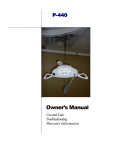
FGA-450 by Prism Medical Introduction ................................................................... 2 Overview ....................................................................... 2 Components of the Floor Lift ........................................ 3 Component List ............................................................. 4 Specifications ................................................................ 5 Cautions ........................................................................ 6 Assembly Instruction .................................................... 7 Operation Charging...……………………………………………...13 Start……...……………………………………………...13 Forward movement….………………………………...14 Turning..………………………………………………...14 Leg Adjustment………………………………………...15 Raising and Lowering Boom………………………….15 Casters and Braking……….……………………….....15 Basics in transferring an individual…………………...….16 Emergency Stop & Lowering……………………………..18 Control Box-Usage Information………………….…….....19 Control Box-Service Information….....………………......20 Technical Specifications ……………………………….....21 Do’s and Don’ts ……………………………………….…...23 Trouble Shooting………………………………….………..24 General inspection and maintenance………..…………..25 Points of Attachment - Checklist …………….…………..26 Service record history……………………………..……....27 Warranty……………………………………………..……...31 Owner’s Manual Use and Care Trouble Shooting Warranty Information 45 Progress Parkway, Maryland Heights, MO 63043 USA T 1.866.891.6502 / 314.692.9135 F 314.692.7858 CAUTION: DO NOT ATTEMPT TO USE THIS EQUIPMENT WITHOUT FIRST UNDERSTANDING THE CONTENTS OF THIS MANUAL. Introduction Before using this equipment, and to ensure the safe operation of your FGA-450 floor lift, carefully read this entire manual, especially the section on “Cautions”. The FGA-450 is designed to be used in conjunction with Prism Medical accessories and slings. Please refer to any user guides supplied with these components and refer to them while reviewing this manual. Should any questions arise from reviewing this manual contact your local authorized Prism Medical Representative. Failure to comply with warnings in this manual may result in injury to either the operator, or the individual being lifted/transferred. Damage to the floor lift and/or related components may also occur. Be sure that the contents of this manual are completely understood prior to using this floor lift. Store this manual with the documents included with the floor lift and sling (s). Contents of this manual are subject to change without prior written notice. Overview of FGA-450 Floor lift The FGA-450 floor lift is a lifting aid used by health care professionals to transfer clients. The floor lift makes it possible to move mobility impaired individuals with minimal strain or risk to the caregiver, while providing complete safety, dignity and comfort for the client. The FGA-450 floor lift is one of two components that make up this technology. The other component, the sling, is a specially designed fabric accessory that attaches to the floor lift by means of a carry bar and straps, and holds an individual while the lift, or transfer takes place. The sling is generally supplied with the floor lift at the initial time of purchase. Please refer to any user guides supplied with the sling and reference them while reviewing this manual. The FGA-450 floor lift has the ability to lift an individual up from one location such as bed, then move the individual to another location and finally lower the individual into a chair or bath. The functions of lifting up or down, or opening and closing the legs on the lift, are accomplished by pressing buttons on the hand control. The hand control is attached to the floor lift. Due to the design of the floor lift system, it takes very little effort to press a button to perform the desired motion. Please familiarize yourself with the components of the FGA-450 floor lift by referring to the diagram on the next page. The Following models are available for FGA-450 floor lift: Models Table for FGA-450 Floor Lift Product Code Product Description 280410 FGA-450/3 - Aluminum Lift 450 lbs., Medium Height Base 280411 FGA-450/3 - Aluminum Lift 450 lbs., Medium Height Base w/Prism QRS Carry Bar 280415 FGA-450/4 - Aluminum Lift 450 lbs., Standard Height Base 280416 FGA-450/4 - Aluminum Lift 450 lbs., Standard Height Base w/Prism QRS Carry Bar FGA-450 - Owner’s Manual Rev: 11/18/12 Page: 2 Components of the FGA-450 Floor Lift Hand Control Boom Mast Up & Down Actuator Push Handle Battery Control Box Prism QRS Carry Bar Leg Spreading Actuator Front Caster Leg Rear Caster w/Brake QRS Locking Carry Bar FGA-450 - Owner’s Manual Rev: 11/18/12 Page: 3 Component List The following components are included with your new FGA-450 floor lift system: • • • • • • FGA-450 floor lift Hand Control Floor Lift Integrated Charger Charger Cord Owner’s Manual Multi Function Wrenches • 5 mm Hex Allen Key (Short Arm) • 4 mm Hex Allen Key (Short Arm) • 3 mm Hex Allen Key (Short Arm) SLINGS: If a sling has been supplied with floor lift, then refer to the instructions included with the sling. ACCESSORIES: If additional accessories such as a weigh scale have been supplied with the floor lift, then refer to the instructions included with those items. IMPORTANT: Before initial use, the floor lift unit must be charged for 4 to 5 hours. Refer to section titled “Charging Instructions”. The Hand control must also be connected to the floor lift. If it is not connected, then refer to the section titled “Assembly Instructions”. FGA-450 - Owner’s Manual Rev: 11/18/12 Page: 4 Technical Specifications– FGA-450 (A) Dimensions and Weight - FGA-450 lift Standard Height Base FGA-450/3 Medium Height Base 450 lbs. (204 kg.) 450 lbs. (204 kg.) Maximum lifting height (See lifting height setting, see “Assembly”, page 8) 70.9 inches (180 cm) 69.7 inches (177 cm) Minimum lifting height (See lifting height setting, see “Assembly”, page 8) 20.5 inches (52 cm) 19.3 inches (49 cm) Height to top of legs 5.5 inches (14 cm) 4.3 inches (11 cm) Clearance from bottom of legs to floor 3.1 inches (8 cm) 2 inches (5 cm) Overall length 52 inches (132 cm) 53 inches (135 cm) Distance inside the legs (min.) 23 inches (58.6 cm) 23 inches (58.6 cm) Distance inside the legs (max.) 41.4 inches (105 cm) 41.4 inches (105 cm) Distance outside the legs (min.) 27.2 inches (69 cm) 27.2 inches (69 cm) Distance outside the legs (max.) 45.3 inches (115 cm) 45.3 inches (115 cm) Reach at maximum height 16.9 inches (42.9 cm) 16.9 inches (42.9 cm) Reach at minimum height 12.6 inches (32 cm) 12.6 inches (32 cm) Maximum Reach-Distance between center of carry bar to front of the mast 23.9 inches (60.7 cm) 23.9 inches (60.7 cm) Turning radius 55.9 inches (142 cm) 57 inches (144.7 cm) Front – 4” (101 mm) Front – 3” (76 mm) Rear – 4” (101 mm) w/brake Rear – 4” (101 mm) w/brake 90.2 lbs (41 kgs) 90.2 lbs (41 kgs) 116 lbs ( 52.7 kgs) 112 lbs (50.8 kgs) FGA-450/4 Specification Maximum weight capacity Wheels (dual-wheel castors) Weight of lift Total Shipping Weight: WGS Box (B) Electrical Specifications - FGA-450 lift Lift Motor: Charger Input: Charger Output: Batteries: Hand Control: Lifting Range: Lift Weight: Maximum Load: Duty Cycle: Rated Performance: 24 VDC, 10.5 Amps Max. 100-240 VAC, 50-60 Hz, 0.4 Amps Max. 24 VDC, 0.65 Amps 24 VDC (2 x 12 VDC) 2.9 Ah, Sealed Lead Acid Electric 16.5” to 66.9” (for Lowest Mast Setting– FGA-450 Standard Base) 90.2 lbs. Maximum load of the installed floor lift is determined by Standard maximum load 450 lbs. referring to the product label located on side of floor lift. 10% use, 90% rest 30 lifts at 450 lbs., 10% duty cycle. Shipping/Storage Conditions: Temperature: -40 to +70 ºC Relative Humidity: 10 to 100% RH Atmospheric Pressure: 500 to 1060 hPa FGA-450 - Owner’s Manual Normal Operating Conditions: Temperature: +10 to +70 ºC Relative Humidity: 30 to 75% RH Atmospheric Pressure: 700 to 1060 hPa Rev: 11/18/12 Page: 5 Cautions: ● Under no circumstance should the FGA-450 floor lift and sling (s) be put in control of a person who has not been properly trained in the use and care of this equipment. Failure to adhere to this warning may result in serious injury to the operator, and/or the individual being lifted/ transferred. ● The FGA-450 floor lift and sling (s) are not toys. Do not use it for unsafe practices. Do not allow children to play with the floor lift or any of its components. ● The manufacturer's warranty is voided if persons unauthorized by Prism Medical Ltd. will perform work on the FGA-450 floor lift. ● There are no user serviceable parts inside the actuator. Do not remove cover screws, or open the unit, as this will VOID THE WARRANTY. ● In facilities where more than one operator will be responsible for using the FGA-450 floor lift and sling (s), it is imperative that all such members are to be trained in its proper use. A training program should be established by the facility to acquaint new operators with this equipment. ● Never expose the FGA-450 floor lift directly to water. Warranty does not cover any misuse or abuse of the floor lift system. ● To maintain optimum function, the FGA-450 floor lift should be inspected and maintained on a regular basis. See the section titled “General Inspection and Maintenance”. ● Any accessories used with the FGA-450 floor lift including sling (s), should be checked to ensure that they are in good working order. Check for signs of wear or fraying prior to use. Report any unusual wear, or damage immediately to your local authorized Prism Medical Service Provider. ● The FGA-450 floor lift and associated sling (s) are intended only for lifting and transferring of a person. Prism Medical will not be responsible for any damage caused by the misuse, neglect or purposeful destruction of the lift, and/or its associated components. ● In any circumstances do not exceed the maximum allowable load of this lift. Refer to the “Specifications” section of this manual, and/or the labels on the side of the lift. ● There is a risk of explosion if the lift is used in the presence of flammable anaesthetics. ● Ensure that a clear space is maintained around the lift. Move any obstacles out of the way before opereating the floor lift. FGA-450 - Owner’s Manual Rev: 11/18/12 Page: 6 Assembly Instructions: 1. Place the Carton/Packaging box in a clear working area, open carefully, and remove following items and place on the floor, taking care to protect the finish from damage. Mast with Boom assembly Base Assembly with Legs attached Battery Pack, and Charging Power Cord Hand Control Tool Kit User Manual, and Test Certificate Caution: Lift parts are heavy, and will need to be lifted with care. Heavier items may need two people for assembly. 2. Place the Base with legs attached on the floor, and lock both rear casters as shown in Figure 1. Figure 1 3. Place the Mast with Boom assembly upright in the tube on the Base assembly as shown in Figure 2. DO NOT STAND ON COVER Figure 2 Caution: Possible finger trap. Keep fingers away from the end of the mast when inserting into the tube on the Base assembly. FGA-450 - Owner’s Manual Rev: 11/18/12 Page: 7 Assembly Instructions: 4. The lifting height can be set at three different levels as shown in Figure 3. In most cases, lifting height at middle hole is recommended. For extra lifting height, the lower most setting (lower hole on the mast) is recommended. For lower lifting height, the upper most setting (upper hole on the mast) is recommended. The distance between two holes is 2 inch / 50mm. For lower lifting height, upper hole on the mast is recommended. Lifting height at middle hole on mast is recommended in most cases. For extra lifting height, lower hole on the mast is recommended. Figure 3 5. Using locking handles, secure the lift mast in the desired position on the base as shown in Figure 4. Tighten the mast locking knob as shown in Figure 5. Adjust the position of the locking handles pointing in downward direction towards the base of lift (or ground) as shown in Figure 5. Locking Handles Mast Locking Knob Figure 4 FGA-450 - Owner’s Manual Figure 5 Rev: 11/18/12 Page: 8 Assembly Instructions: 6. Remove the screws from the mounting position of push handle on Mast assembly. Insert the screws through the push handle bracket, and mount on the Mast assembly as shown in Figure 6, and 7. Figure 7 Figure 6 Attaching QRS Locking Carry Bar to Lift: 7. To attach QRS locking carry bar to the lift, tilt the carry bar to almost 90°, and push the latch to the swivel mount holder bolt as shown in Figure 8, and 9. Make sure that swivel mount of carry bar is correctly seated on the swivel mount holder bolt as shown in Figure 10. Figure 8 Figure 9 Figure 10 FGA-450 - Owner’s Manual Rev: 11/18/12 Page: 9 Assembly Instructions: Attaching 2 Point QRS Carry Bar to Lift: 8. To attach 2 Point Quick Release Carry Bar to the Quick Release Hook, tilt the carry bar, and push the dowel pin of carry bar to the latch of QRS hook so that latch will open and dowel pin will be inserted into the QRS hook as shown in Figure 11.. Make sure that latch is closed safely after the dowel pin sitting into the QRS hook as shown in Figure 12. Figure 12 Figure 11 Detaching QRS Locking Carry Bar, and 2 Point QRS carry bar from the Lift: 9. To detach the QRS Locking Carry Bar from Quick Release Hook, Open the latch by pushing the latch down as shown in Figure 13. While keeping the latch pushed down, Tilt the carry bar approximately 90 degree, and remove the carry bar from the quick release hook as shown in Figure 14. Apply the same procedure to detach Prism QRS Carry Bar from lift as shown in Figure 14A, and 14B. Figure 13 Figure 14 Figure 14B Figure 14A FGA-450 - Owner’s Manual Rev: 11/18/12 Page: 10 Assembly Instructions: 10. Remove the middle screw from the mounting bracket using 3 mm Allan Key as shown in Figure 15. 11. Press the FGA-450 CBJ Care Control Box against the mounting bracket and slide it down. The control box should be seated securely on top of the edge of bracket as shown in Figure 16. 11. Mount the Control Box to the mounting bracket using same screw that you removed from the middle of the bracket as shown in Figure 17. Figure 15 Figure 16 Figure 17 12. To install the battery, you will need to press the battery against the bracket and slide it down until it sits straight on top of the control box as shown in Figure 18. Make sure to secure the battery box by latching the battery lock into the bracket as shown in Figure 19. Figure 19 Figure 18 FGA-450 - Owner’s Manual Rev: 11/18/12 Page: 11 Assembly Instructions: 13. Connect all the cables to the control box as shown in the picture below. A. Connect the Hand Control connector to the large circle on the left side of the control box as shown in the Figure 20. B. Connect the Up/down Actuator Cable connector to the second circle (Marked No. 1) from the left side of the control box as shown in the Figure 21. C. Connect the Leg Spreading Actuator Cable connector to the third circle (Marked No. 2) from the left side of the control box as shown in the Figure 22. D. Connect the Mains Cable/Power Cord to the rectangular outlet on the control box as shown in the Figure 23. Figure 20 Figure 21 Figure 22 Figure 23 232 14. Please make sure to charge battery before initial use and before each operation of floor lift. After assembly, check to ensure that: 1. 2. 3. 4. 5. Lifting actuator moving up and down with the buttons on the hand control, and control box. Emergency lowering (mechanical, and electrical) functions works properly. Rear wheel brakes works properly. Leg spreading actuator works properly. Batteries are fully charged. FGA-450 - Owner’s Manual Rev: 11/18/12 Page: 12 Operation: Caution: Visually inspect the floor lift before using for any unusual wear and tear. Should anything look unusual then contact your local representative prior to use. Failure to comply with this caution could result in serious injury to the operator, the individual being lifted and/or damage to the lift. Because of the safety function in the actuator the lifting arm and hanger bar can “fall down” to the height of the spindle. Therefore, both before and after each lifting operation, press the lifting arm down to ensure that it is supported by the actuator. This must be done, to remove the possibility of the lifting arm “falling down” and the risk of subsequent injury occurring. Charging: The “On” light illuminates when you plug the control box to the power outlet and should turn off when it is unplugged. The “Charge” light illuminates, and when you connect the battery to the control box and it is charging, also the LCD displays shows the symbol of mains cable plug in as shown in the Figure 24. The “Charge” light will turn off when the battery is finished charging. The lift should be plugged in for charging whenever the lift is not in use to get the max number of cycles out of the battery. An audible battery alarm will sound when approximate 25% of battery capacity remaining. To obtain max life, charge the battery at no more than 30% discharge. Please Note: The battery can be charged whether the Emergency Stop is activated or not. Charging Indicator Light ON when Lift is charging Display shows Mains Cable Plug in Figure 24 Start: The Hand Control has four functions up/down and in/out. Press down on the symbols to operate the desired function. It is not possible to use two functions at the same time. An audible alarm will sound once the load becomes too great on the lift. This will cause the lifting operation to stop. Do not continue to operate the handset by repeatedly pressing the buttons. At this point the lift has reached it's maximum lift. This is a purposefully built in safety feature. Please Note! The emergency stop must be released at all times during normal operation. FGA-450 - Owner’s Manual Rev: 11/18/12 Page: 13 Operation: Forward Movement: To move the lift forward, hold onto the handle bar and push forward. HANDLE BAR Turning: DO NOT STAND ON COVER OR DO NOT PUSH ON COVER When turning the lift, stand on along one side. With one hand pull gently on the handle bar, and with the other hand push gently away on the lifting arm. In this way the lift will rotate around its own axis. This movement is performed with a smooth, slow action to avoid swinging the patient unnecessarily. Warning: Do not hold on to the actuator or swing link when turning the lift as there is a risk of getting your fingers caught. FGA-450 - Owner’s Manual Rev: 11/18/12 Page: 14 Operation: Leg Adjustment: The legs of FGA-450 lift are electrically adjustable for opening, and closing base width. The legs can be opened to enable access around arm chairs or wheel chairs. For transferring through narrow doorways, and passages the lift legs should be in closed position. Leg adjustment is achieved by pressing appropriate buttons on the hand control. The legs’ motion will be stopped whenever the hand control button is released. Raising and Lowering the Boom: The up and down movement of the boom of the FGA-450 lift is achieved by a powerful electric actuator which is controlled by hand control. The hand control has two buttons with directional arrows UP and DOWN. The actuator stops automatically at the limit of travel in both directions. Casters and Braking: The FGA-450 lift has two rear casters with brakes. The rear casters can be braked for rotation, lateral movement, and parking. To apply the brake, press the brake pedal down with your foot. To release the brake, press the raised pedal towards the wheel. During the lifting, the rear wheels should remain unlocked so that the lift will move to the patient’s centre of gravity. The wheels should, however, be locked if there is a risk of lift moving to the patient. For example, when lifting the patient from the floor. Warning: Locked wheels during lifting will increase the risk of the lift tilting over. Application: If the lift is used incorrectly any warranty or product liability might cease to be valid. The mobile lift must only be used for person lifting and only for persons who, including the sling, do not weigh more than the stated max. weight load. If the load exceeds the stated weight limit and if the lift is used for lifting anything but persons, then any product liability that Prism Medical might have, in connection with insurance / warranty / maintenance etc., will cease to be valid. To avoid possible accidents and injury to persons being lifted, the floor lifts must only be operated as described in the preceding pages. FGA-450 - Owner’s Manual Rev: 11/18/12 Page: 15 Basics in transferring an individual Caution: The following steps are intended to generally illustrate the procedure involved in the lifting and transferring of an individual from one location to another using the floor lift. The manual for the sling that was purchased with the lift should be reviewed in detail prior to attempting these steps, as the sling illustrated here may not be the same as the one that was purchased. Contact your local authorized Prism Medical Representatives if you have any questions or concerns. Step 1) Unplug the lift from its charging station or current location and move close to the individual that is to be transferred. Use the procedures for up and down and transferring as described in the sections titled, “Start”, “Forward Movement” and “Turning”. Caution: Always use extreme care when moving the lift from one location to another. Watch out for and avoid any obstructions that may cause injury to the individual in the sling, or damage to the lift. Step 2) Prepare the individual being transferred with the appropriate sling. Refer to the instructions supplied with the sling that was purchased on how to properly outfit an individual with a sling. Caution: Always make sure that the sling is correctly fitted and adjusted on each side of the individual so that maximum comfort and safety are achieved prior to lifting. Step 3) Once the individual has been outfitted with the sling, move the lift so that it is positioned directly over the individual and utilize leg opening function if required. Lower the carry bar to a height so that the straps of the sling can be easily attached to the carry bar. Caution: Always check to ensure that the lift is correctly positioned directly above the person to be lifted. Caution: Check to ensure that the carry bar has no cuts, dents or sharp edges that may come in contact with the straps of the sling and cause damage to them. Report any concerns to your local authorized representative. Step 4) Attach the straps of the sling to the hooks of the carry bar. The straps on each side of the sling are generally attached to the corresponding side of the carry bar. Be sure to double check to ensure that the straps are properly attached to the carry bar, and that the individual being lifted is properly positioned in the sling prior to lifting. Caution: Prior to lifting an individual make sure that the straps of the sling are securely placed on the hooks of the carry bar. FGA-450 - Owner’s Manual Rev: 11/18/12 Page: 16 Basics in transferring an individual … continued Step 5) The individual may now be raised using the UP button on the hand control. While lifting is in progress the height required in order for the transfer to be completed safely should be closely observed. Ensure that the individual being lifted will not be injured by any obstructions during the initial lifting. Caution: Always use caution when lowering/raising an individual who is in the sling of the lift. Watch out for and avoid any obstructions that may cause injury to the individual, or damage to the lift. Step 6) Once at the correct height the individual can be moved to the desired location. Refer to the sections already described in this manual on how to do so. Step 7) Once at the desired location the individual in the sling can be lowered/raised to the correct height in order to complete the transfer. On completion of lowering/raising ensure that the individual is properly positioned and safely supported prior to removing the straps of the lift from the carry bar. Caution: Prior to removing the straps of the sling from the carry bar be sure to check that the individual being lifted is securely supported in the final desired position. Step 8) Lower the carry bar sufficiently to allow the straps of the sling to be easily removed from the carry bar. Take care not to let the carry bar come in contact with the individual in the sling. The straps from the sling can now be removed from the carry bar. The lift should then be moved away from the immediate area so that it will not interfere with the removal of the sling from the client. Step 9 ) The sling can now be gently removed from the individual. It should then be stored in a safe place for future use. Step 10) The lift can now be moved to a safe location until further use, or relocated to its original location. The lift should be turned off when not in use. It is recommended that the lift be left on charge when not in operation. Refer to the section titled, “Charging the lift” for instructions on charging. FGA-450 - Owner’s Manual Rev: 11/18/12 Page: 17 Emergency Stop & Lowering: Caution: The manual emergency lowering system should be used only if the lowering procedures described in the previous section of the manual do not work. Should you have any concerns or questions contact your local authorized Prism Medical Representative. Caution: DO NOT use the lift after the manual lowering mechanism has been used. The lift must be reset by a qualified lift technician after use. Contact your local authorized Prism Medical Service Provider. Emergency Stop: Push the Emergency Stop button to cut all power on the Floor Lift. To resume power, release the emergency stop button by turning in the direction as indicated by arrows on the Emergency Stop button. Electrical emergency lowering/raising: The lift boom is lowered or raised by pressing the UP and DOWN arrow button on the control box. Electrical emergency leg adjustment: The lift legs are opened or closed by pressing the leg opening, and leg closing arrow button on the control box. Emergency Stop Button Emergency Lowering Button Emergency Raising Button Emergency Leg Closing Button Emergency Leg Opening Button Mechanical emergency lowering: In case of power failure, it is possible to mechanically lower a patient placed in FGA-450 lift. In order to lower the boom in an emergency situation, pull up the red lever located directly on the lift’s actuator. The boom will lower as you press up and hold the lever. Release the red lever once you have lowered the boom to a safe position. FGA-450 - Owner’s Manual Rev: 11/18/12 Page: 18 Control Box: Usage information The control box of FGA-450 lift having LCD display to have some basic usage information on the display. Following information will be visible on the LCD display of control box. When it is time for service the service symbol will appear on the display will light up and give notice to users about the need for service. If the lift stops because of overload, the symbol will appear on the display and give user the information about why the lift is stopped. If someone tries to use the lift while mains plugged in, the symbol will appear on the display. The user receives the information about why the lift is not working. Usage of lift while charging is not possible. The display showing a full battery symbol indicates that the battery is fully charged. The display showing a half empty battery symbol indicates that it is time to charge the battery. The display showing a empty battery symbol indicates that no battery is completely discharged. The display showing a lifting actuator is moving up. The display showing a lifting actuator is moving down. The display showing a legs are opening. The display showing a legs are closing. FGA-450 - Owner’s Manual Rev: 11/18/12 Page: 19 Control Box: Service information The control box of FGA-450 lift having LCD display to have some basic service data on the display. To get this information, press the “lifting arm up” button on hand control for half a second. The information that appears on the display is as shown below. Total cycles made by lifting actuator Total work made by lifting actuator (A x S) Total number of overloads Number of days since last service / Number of days between services Total cycles made by lifting actuator: One cycle is defined as; Moving with load (the actuator draws more than 1.5 Amps). Moving direction up for a minimum of 5 seconds (several activations are allowed), followed by moving down for a minimum of 2 seconds. Total work made by lifting actuator: Work indicator for the lifting actuator measures via ampere usage x seconds in use. The work indicator gives very good indication of how worn is the actuator. Typical minimum lifetime performance without abuse of the actuator is 10000 cycles in life test equals to 5,600,000 A x S. Total number of over loads: Counts the number of times the lifting actuator has been overloaded. Resetting of Service interval after service has been carried out: Resetting of service is done by pressing 2 buttons; Lifting arm UP, and lifting arm DOWN on the hand control at the same time for 5 seconds. After pressing the buttons for 5 seconds, you will receive an audio signal indicating that the timer has been reset. The timer will clear the display for service symbol, and start counting a new service period. FGA-450 - Owner’s Manual Rev: 11/18/12 Page: 20 Technical Specifications– FGA-450 Standard Base FGA-450 - Owner’s Manual Rev: 11/18/12 Page: 21 Technical Specifications– FGA-450 Medium Height Base FGA-450 - Owner’s Manual Rev: 11/18/12 Page: 22 DO’S & DON’TS DO Do charge the battery whenever possible. This will extend the battery life. A large number of cycles can be obtained from operating on the batteries, but battery lifetime is reduced with frequent discharging. Do inspect all cables particularly the mains power cable on the charger for any damage; replace where necessary. Do stow the handset and if fitted with charger, the mains power cable when transporting the hoist. Do clean the actuators, control box, charger, battery and handset at regular intervals to remove dust and dirt. The exterior of the lift should only be cleaned, disinfected and sterilized using isopropyl alcohol. Damp a cloth with isopropyl alcohol and wipe down entire exterior of lift. No other chemicals and/or liquids should be used to clean, disinfect and sterilize this lift. Caution: Take great care to ensure that no liquids get inside the lift. This lift is not drip proof or water tight. Failure to protect the lift from liquids may result in damage to the lift and/ or may cause personal injury. DON'T Don't allow the batteries to fully discharge before connecting to the charger. The batteries are a leadacid gel cell type that can be trickled charged continuously (batteries used for standby) and have a high current discharge capacity. Life is greatly reduced by deep or complete discharging of the batteries. Longer lifetime is obtained by maintaining fully charged batteries. Don't continue to operate the handset by repeatedly pressing the buttons if the lift function will not move or the actuator will not function. If this occurs then the actuator has either reached its end position, the load is too great or there is a malfunction. Don't exert excessive force on the handset cable as this may break off the wires inside the cable and prevent some or all of the operations. Don't continually operate the hoist functions. The system is not designed for continuous operation. Continuous Operation will cause batteries to be deeply discharged or to damage the actuator or control box by overheating. FGA-450 - Owner’s Manual Rev: 11/18/12 Page: 23 Trouble Shooting Should problems arise with the use of the lift review the following chart. Find the fault and complete the recommended solution. If the fault is not found and/or the solution does not correct the problem contact your local Prism Medicalauthorized Service Provider for service immediately. PROBLEM SOLUTION Lift cannot raise/lower, control box is not clicking. Lift cannot raise/lower, control box is clicking. Lifting actuator cord (1) is not fully plugged into slot (1) Hand control is not properly plugged in. Hand control is defective. Control box is defective. on the control box. Lifting actuator is defective. Lifting actuator cord (1) is not fully plugged into slot (1) Emergency Lower button on control box does not lower. on the control box. Lifting actuator is defective. Control box is defective. Lift cannot spread or close legs, control box is not clicking. Hand control is not properly plugged in. Hand control is defective. Control box is defective. Lift cannot spread or close legs, control box is clicking. Leg spreading actuator cord (2) is not fully plugged into slot (2) on the control box. Leg spreading actuator is defective. Cannot move lift. Rear caster brake is engaged. Casters are defective. Cannot tighten Mast into Base tube. Mast locking assembly are defective, replace with new Mast locking assembly . FGA-450 - Owner’s Manual Rev: 11/18/12 Page: 24 General Inspection and Maintenance A) Each Use - To be completed by User All functions on hand control are operational. B) Semi-Annually - To be completed at least every 6 months. Should any of these items fail the inspection do not use the lift. Contact Prism Medical Systems or your local qualified service technician for service. Complete the inspection as noted in the “Each Use” section above. Also check the following: Battery charger functional. Weigh scale functional (if applicable). Casters are clean and free of debris. All bolts and attachment points are secure (see next page for “Points of Attachment”) Visual inspection of all weld points and cast components. Check operation of the emergency stop button. C) Annually - To be completed at least every 12 months. Complete the inspection as noted in the “Semi-Annually” section above. Also check the following: Perform a working load test of one (1) lifting cycle with the maximum load. This is in accordance to the periodic inspection requirements of ISO10535. Check functional operation of the emergency lowering mechanism. All bolts in connection with the carry bar must be inspected, greased and tightened. All defective or worn components must be replaced. Connection bolts/bearings between arm and mast to be inspected. All defective or worn components must be replaced. Leg spreading function to be tested and all bolts to be inspected. All defective or worn components must be replaced. Check that main actuator is functional. This section to be only completed by a qualified service technician as authorized by Prism Medical Ltd. Use the provided service record history sheets to note findings during inspection. FGA-450 - Owner’s Manual Rev: 11/18/12 Page: 25 Floor Lift - Points of Attachment Use the described tools to tighten the bolts on a monthly basis in the areas shown. 13mm Wrench Actuator mounting 5mm Allen Key Push Handle 17 mm Wrench Carry bar mount 4mm Allen KeyMounting Bracket 3mm Allen KeyMounting Control Box 13mm Wrench Actuator mounting Locking Handle FGA-450 - Owner’s Manual Rev: 11/18/12 Page: 26 Service Record History - Initial Information Complete the following section on Purchase and Service Information as soon as this equipment is purchased. Use the service record history to record to any completed service and repairs. Ensure that the service record is signed and dated each time it is used. Be sure to have this piece of equipment serviced on a regular basis as described in the General Inspection and Maintenance Section. PURCHASE INFORMATION: Product Name: FGA-450 Bariatric floor lift Model #: ________________________ Serial #:________________________ Date of Purchase: _____________________ Purchased From: ___________________________________________________________ (local authorized Prism Medical Representative) Address: _______________________________________ City: __________________________ Telephone No: __________________________ Postal Code: ________________ Comments: SERVICE INFORMATION: Contact the following company for service: Company: ___________________________________________________________ (local authorized Prism Medical Representative) Address: _______________________________________ City: __________________________ Telephone No: __________________________ Postal Code: ________________ Comments: FGA-450 - Owner’s Manual Rev: 11/18/12 Page: 27 Service Record History Date: _______________________ Service Type: □ Periodic Inspection □ Monthly Inspection Completed By: _________________________ Complete this section after each service, repair inspection and/ or maintenance. Photocopy additional pages as required. Time: ________________________ □ 6 Month Inspection □ Repair □ Yearly Inspection □ Other:_________ _____________________________ Printed Name Signature Company: _____________________________________________________________ Remarks & Action Taken: Date: _______________________ Service Type: □ Periodic Inspection □ Monthly Inspection Completed By: _________________________ Time: ________________________ □ 6 Month Inspection □ Repair □ Yearly Inspection □ Other:_________ _____________________________ Printed Name Signature Company: _____________________________________________________________ Remarks & Action Taken: Date: _______________________ Service Type: □ Periodic Inspection □ Monthly Inspection Completed By: _________________________ Time: ________________________ □ 6 Month Inspection □ Repair □ Yearly Inspection □ Other:_________ _____________________________ Printed Name Signature Company: _____________________________________________________________ Remarks & Action Taken: Date: _______________________ Service Type: □ Periodic Inspection □ Monthly Inspection Completed By: _________________________ Time: ________________________ □ 6 Month Inspection □ Repair □ Yearly Inspection □ Other:_________ _____________________________ Printed Name Signature Company: _____________________________________________________________ Remarks & Action Taken: Date: _______________________ Service Type: □ Periodic Inspection □ Monthly Inspection Completed By: _________________________ Time: ________________________ □ 6 Month Inspection □ Repair □ Yearly Inspection □ Other:_________ _____________________________ Printed Name Signature Company: _____________________________________________________________ Remarks & Action Taken: Date: _______________________ Service Type: □ Periodic Inspection □ Monthly Inspection Completed By: _________________________ Time: ________________________ □ 6 Month Inspection □ Repair □ Yearly Inspection □ Other:_________ _____________________________ Printed Name Signature Company: _____________________________________________________________ Remarks & Action Taken: FGA-450 - Owner’s Manual Rev: 11/18/12 Page: 28 Service Record History Date: _______________________ Service Type: □ Periodic Inspection □ Monthly Inspection Completed By: _________________________ Complete this section after each service, repair inspection and/ or maintenance. Photocopy additional pages as required. Time: ________________________ □ 6 Month Inspection □ Repair □ Yearly Inspection □ Other:_________ _____________________________ Printed Name Signature Company: _____________________________________________________________ Remarks & Action Taken: Date: _______________________ Service Type: □ Periodic Inspection □ Monthly Inspection Completed By: _________________________ Time: ________________________ □ 6 Month Inspection □ Repair □ Yearly Inspection □ Other:_________ _____________________________ Printed Name Signature Company: _____________________________________________________________ Remarks & Action Taken: Date: _______________________ Service Type: □ Periodic Inspection □ Monthly Inspection Completed By: _________________________ Time: ________________________ □ 6 Month Inspection □ Repair □ Yearly Inspection □ Other:_________ _____________________________ Printed Name Signature Company: _____________________________________________________________ Remarks & Action Taken: Date: _______________________ Service Type: □ Periodic Inspection □ Monthly Inspection Completed By: _________________________ Time: ________________________ □ 6 Month Inspection □ Repair □ Yearly Inspection □ Other:_________ _____________________________ Printed Name Signature Company: _____________________________________________________________ Remarks & Action Taken: Date: _______________________ Service Type: □ Periodic Inspection □ Monthly Inspection Completed By: _________________________ Time: ________________________ □ 6 Month Inspection □ Repair □ Yearly Inspection □ Other:_________ _____________________________ Printed Name Signature Company: _____________________________________________________________ Remarks & Action Taken: Date: _______________________ Service Type: □ Periodic Inspection □ Monthly Inspection Completed By: _________________________ Time: ________________________ □ 6 Month Inspection □ Repair □ Yearly Inspection □ Other:_________ _____________________________ Printed Name Signature Company: _____________________________________________________________ Remarks & Action Taken: FGA-450 - Owner’s Manual Rev: 11/18/12 Page: 29 Service Record History Date: _______________________ Service Type: □ Periodic Inspection □ Monthly Inspection Completed By: _________________________ Complete this section after each service, repair inspection and/ or maintenance. Photocopy additional pages as required. Time: ________________________ □ 6 Month Inspection □ Repair □ Yearly Inspection □ Other:_________ _____________________________ Printed Name Signature Company: _____________________________________________________________ Remarks & Action Taken: Date: _______________________ Service Type: □ Periodic Inspection □ Monthly Inspection Completed By: _________________________ Time: ________________________ □ 6 Month Inspection □ Repair □ Yearly Inspection □ Other:_________ _____________________________ Printed Name Signature Company: _____________________________________________________________ Remarks & Action Taken: Date: _______________________ Service Type: □ Periodic Inspection □ Monthly Inspection Completed By: _________________________ Time: ________________________ □ 6 Month Inspection □ Repair □ Yearly Inspection □ Other:_________ _____________________________ Printed Name Signature Company: _____________________________________________________________ Remarks & Action Taken: Date: _______________________ Service Type: □ Periodic Inspection □ Monthly Inspection Completed By: _________________________ Time: ________________________ □ 6 Month Inspection □ Repair □ Yearly Inspection □ Other:_________ _____________________________ Printed Name Signature Company: _____________________________________________________________ Remarks & Action Taken: Date: _______________________ Service Type: □ Periodic Inspection □ Monthly Inspection Completed By: _________________________ Time: ________________________ □ 6 Month Inspection □ Repair □ Yearly Inspection □ Other:_________ _____________________________ Printed Name Signature Company: _____________________________________________________________ Remarks & Action Taken: Date: _______________________ Service Type: □ Periodic Inspection □ Monthly Inspection Completed By: _________________________ Time: ________________________ □ 6 Month Inspection □ Repair □ Yearly Inspection □ Other:_________ _____________________________ Printed Name Signature Company: _____________________________________________________________ Remarks & Action Taken: FGA-450 - Owner’s Manual Rev: 11/18/12 Page: 30 Warranty This Warranty does not affect or in any way limit your Statutory Rights 1) Prism Medical guarantees all equipment supplied as new, against failure within the period of 1 year from date of purchase by virtue of defects in material or workmanship. 2) This warranty does not apply to failure attributable to normal wear and tear, damage by natural forces, user neglect or misuse or to deliberate destruction, or to batteries more than 90 days after original purchase. 3) This equipment warranty shall be void if the equipment is not serviced by Prism Medical or its authorized service agents in accordance with the manufacturer’s recommendations or if any unauthorized person carries out works on the equipment. 4) The liability of Prism Medical under the terms of this guarantee shall be limited to the replacement of defective part (s) to the sales distributor, dealer, agent, person or entity which purchased the equipment from Prism Medical. In no event shall Prism Medical incur liability for any consequential or unforeseeable losses. If you have any questions about the manufacture or operation of this equipment, please contact Waverley Glen, or your local authorized dealer. 45 Progress Parkway Maryland Heights, MO. 63043 USA Phone: (314) 692-9135 Fax: (314) 692-7858 Toll Free: 1-866-891-6502 www.prismmedicalltd.com This document conforms to EN ISO 10535 requirements ™ Trade-mark of Corven Health Care Inc. Used under licence. E.& O.E. FGA-450 - Owner’s Manual Rev: 11/18/12 Page: 31