1
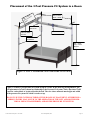
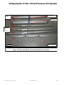
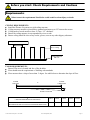
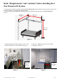
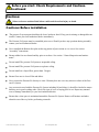
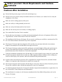
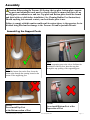
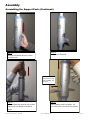
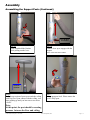
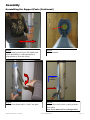
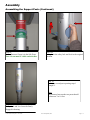
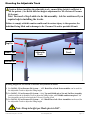
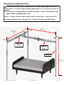
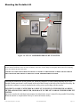
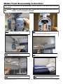
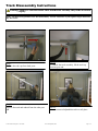
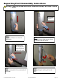
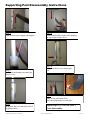
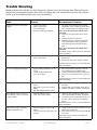
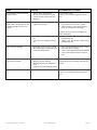
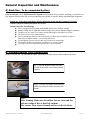
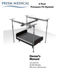
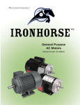
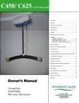
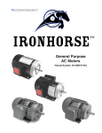
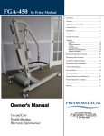
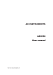
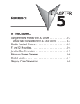
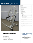
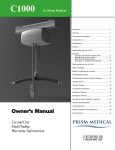
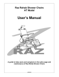
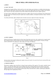
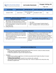
3 Post
Pressure Fit System
Owner’s
Manual
Use and Care
Trouble Shooting
Warranty Information
Table of Contents
3 Post Pressure Fit System
Introduction........................................................................................... 3
Overview of the 3 Post Pressure Fit System .............................. 3
Placement of the 3 Post Pressure Fit System ........................... 4
Components of 3 Post Pressure Fit System ............................... 5
Component list ..................................................................................... 6
Specifications of the 3 Post Pressure Fit System .................... 6
Requirements and Cautions............................................................. 7
Assembly
Assembling the Support Posts ............................................... 11
Mounting the Adjustable Track ............................................. 16
Assembly 3rd Post…………………………………………………..18
Assembly 3rd post and Middle track………………………….19
Completed Pressure Fit System ................................. 21
Final Inspection Prior to Use .................................................. 23
Mounting the Portable Lift ......................................... 24
Disassembly
Middle track Disassembly ……………………………………….25
Track Disassembly Instructions ........................................... 26
Support Post Disassembly Instructions .............................. 27
Trouble Shooting ............................................................................... 29
General inspection and maintenance ......................................... 31
Service record history ..................................................................... 33
Warranty ............................................................................................... 37
3 Post Pressure Fit System - User Guide
Rev: 2lst September, 2011
Page: 2
CAUTION: DO NOT ATTEMPT TO USE THIS EQUIPMENT
WITHOUT FIRST UNDERSTANDING THE CONTENTS OF
THIS MANUAL.
Introduction
Before using this equipment, and to ensure the safe operation of your Pressure Fit System, carefully read this
entire manual, especially the section on “Requirements & Cautions”. The Pressure Fit System is designed
to be used in conjunction with Prism Medical Ltd. portable lift units, accessories and slings. Please refer to
any user guides supplied with these components and reference them while reviewing this manual.
Should any questions arise from reviewing this manual contact your local authorised Prism Medical dealer.
Failure to comply with warnings in this manual may result in injury to the operator, or the individual being
lifted/transferred. Damage to the lift and/or related components may occur. Be sure that the contents of this
manual are completely understood prior to using this piece of equipment.
Store this manual with the documents included with the lift system and sling (s). Contents of this manual are
subject to change without prior written notice.
Overview of the 3 Post Pressure Fit System
The Pressure Fit System is a lifting aid used by health care professionals and those providing care in the home
to lift, position and transfer clients or a disabled family member. The Pressure Fit System is part of what is
termed overhead lift technology which takes advantage of lifting from above and not from below or the side.
The Pressure Fit System makes it possible to move mobility impaired individuals with minimal strain or risk
to the caregiver, while providing complete safety, dignity and comfort for the client or family member.
The Pressure Fit System is designed to work with a Prism Medical portable lift system such as the
P-440. Use of other portable lift units with this system may be possible but not P-600 because capacity of
pressure fit system is 440 lbs. However, please contact your local authorised Prism Medical Ltd dealers in order to obtain approval before use.
The Pressure Fit System can be used to lift and transfer individuals from a bed, chair or similar fixture. The
length is adjustable and thus can be assembled to suit a wide range of applications. The Pressure Fit System is
easy to assemble and can be completed by just one person in a short period of time. Additionally, no tools are
required. It is also light in weight and once dismantled, can be moved to another location such as a hotel or cottage.
Please review the following pages that outline the parts included with your package. Should you have any
questions about this product or its use contact your local authorized dealer.
3 Post Pressure Fit System - User Guide
Rev: 2lst September, 2011
Page: 3
Placement of the 3 Post Pressure Fit System in a Room
MIN. 6 FEET
MAX. 8 FEET
T
EE
7 F FEET
.
N
MI X. 10
MA DE
WI
SWIVEL
TROLLEY
ADJUSTABLE
TRACK
LIFT TROLLEY
SIDE SUPPORT
ASSEMBLY
MIN. 7 FEET
MAX. 9 FEET
HEIGHT
Figure 1A– FULLY ASSEMBLED 3 POST PRESSURE FIT SYSTEM
Figure 1-A shows 3 post pressure fit system set up in a room. In this drawing arrangement, a general placement of a bed is shown in relationship to the Pressure Fit System. Notice that there is still
room for a wheelchair to be placed beside the bed. The view shows min and max height and width
of the pressure fit system for which it can be set up.
DO NOT USE THE SYSTEM OUTSIDE OF THIS RANGE OF PLACEMENT OTHERWISE A
SERIOUS INJURY MAY OCCUR TO THE OPERATOR OF THE LIFT AND/OR THE INDIVIDUAL BEING TRANSFERRED, AND/OR THE PRESSURE FIT SYSTEM.
3 Post Pressure Fit System - User Guide
Rev: 2lst September, 2011
Page: 4
Components of the 3 Post Pressure Fit System
Adjustable
Track
Swivel Trolley
Lift Trolley
Supporting
Post
Sections
Bottom Foot
Top Foot
Figure 1B - DISASSEMBLED 3 POST PRESSURE FIT SYSTEM
3 Post Pressure Fit System - User Guide
Rev: 2lst September, 2011
Page: 5
Component List
The following components are included with your new Pressure Fit System:
Description
Quantity
Bottom Foot
3
Top Foot
3
Supporting Post
3
Adjustable Track
2
Swivel Trolley
1
Lift Trolley
1
Owners Manual
1
Warranty Card
1
Specifications of the Pressure Fit System
High-strength lightweight Aluminum
Portable or semi-permanent installation
Eliminates the mounting of a connection system in the ceiling
Pressure gauge indicator to help ensure proper installation
Quick attachment with secure fixings
Addresses a number of different bedroom & bathroom situations
Weight capacity 440 lbs
Adjustable in length
Built-in easy-slide trolley
Exerting pressure between Floor and Ceiling is 80 to 100 lbs.
Specially designed and engineered rubber molded feet for ultimate grip
Leveling indicators on posts
One (1) year warranty
Minimum - Maximum Dimensions
7 to 10 feet
Model Table for the Pressure System
6 to 8 feet
Code
Description
341502
3 Post Pressure Fit System
7 to 9 feet
3 Post Pressure Fit System - User Guide
Rev: 2lst September, 2011
Page: 6
Before you start: Check Requirements and Cautions
Requirements:
Failure to meet the requirements listed below could result in serious injury or death.
CEILING REQUIREMENTS:
Install the Pressure fit system to a rigid ceiling structure.
Ceiling structure must have joists that are spanned maximum up to 24” between the trusses.
Ceiling made of wood must be at least 12.7mm / 1/2” thickness.
Ensure the ceiling structure is not suspended by wires or rods.
Ensure ceiling should be clear of any cracks, grease, water or any other slippery substance.
Joist Span should be max 24 “
Joist framework
Above ceiling
Ceiling Thickness
Min 1/2”
FLOOR REQUIREMENTS:
Ensure Floor area is cleaned and free of dirt & debris.
Floor should meet the requirements of building code standards.
Floor must not have a slope of more than .5 degree. See table below to determine the slope of floor.
FLOOR
ONE END
FLOOR
OTHER END
X
Y
SLOPE OF FLOOR
X
( DISTANCE BETWEEN FLOOR ENDS)
6 FEET
Y
.630”
(MAXIMUM SLOPE OF FLOOR AT SPECIFIED DISTANCE)
3 Post Pressure Fit System - User Guide
Rev: 2lst September, 2011
7 FEET
8 FEET
9 FEET
10 FEET
.733”
.837”
.942”
1.047”
Page: 7
Read "Requirements" and ―cautions‖ before installing the 3
Post Pressure Fit System.
1. Examine the room where you plan to install the 3 Post Pressure Fit System. Make sure the room meets all the specifications outlined in " Ceiling and Floor Requirements".
2. Use the measurements mentioned in the figure below to determine the best spot to place 3 Post Pressure Fit
System:
MIN. 7 Feet
MAX. 10 Feet
WIDE
MIN. 6 Fee
t
MAX. 8 F
eet
MIN. 7 Feet
MAX. 9 Feet
HEIGHT
Figure 1
3. Install the Pressure Fit system approx. 36-40" away
from the head of bed or wall of the Room (Figure 2).
4. Allow 36" (1000 mm) of open area for transfer
working space (Figure 3).
36”- 40”
Away from
wall or
head board
Figure 2
3 Post Pressure Fit System - User Guide
36”
Away from
Bed
Figure 3
Rev: 2lst September, 2011
Page: 8
Before you start: Check Requirements and Cautionscontinued
Cautions:
Failure to observe cautions listed below could result in serious injury or death.
Cautions: Before installation
The pressure fit system parts should not be loose, broken or bend. If any part is missing or damaged do not
install. Contact your local authorized dealer immediately.
The Pressure Fit System must be assembled prior to use. Should you have any questions during assembly
contact your local authorised dealer.
Never installed the Bottom foot plate on the top portion of post section or vice versa. See section
“Assembly” instructions.
Ensure rubber feet are cleaned and dry prior to each use. See section “ General Inspection and maintenance”.
Do not install The pressure Fit System to suspended ceiling.
Do not install The pressure Fit System on a plaster ceiling.
Do not install on a sloped floor greater than .5 degree.
Ensure floor area is clear off dirt and debris.
Never expose the Pressure Fit directly to water. Warranty does not cover any misuse or abuse of the Pressure Fit system.
Any accessories used with the Pressure Fit System including lift and sling (s), should be checked to ensure
that they are in good working order. Check for signs of wear or fraying prior to use. Report any unusual
wear or damage immediately to your local authorised dealer.
Ensure that a clear space is maintained around the Pressure Fit System. Remove all furniture and other
obstacles out of the way before performing a transfer.
3 Post Pressure Fit System - User Guide
Rev: 2lst September, 2011
Page: 9
Before you start: Check Requirements and Cautionscontinued
Cautions: After Installation
Ensure that the pressure gauge is in the safe zone during set up.
Ensure Posts are level both visually and with the built in level. If unsure, use a master level to verify the
straightness of the Posts.
Make sure track is sitting properly on the posts.
Make sure trolley is sliding smoothly on the track.
Make sure safety lock button and level are locked.
Make sure the end stop for swivel trolley is working properly.
Never unlock the Post when Track is attached.
Do not under any circumstance exceed the maximum load rating for this piece of equipment. Refer to the
“Specifications” section of this manual. Do not use P-600 lift.
The installation of the Pressure Fit System, lift, accessories, and sling are certified to a maximum load. Do
not exceed the maximum rated load of any of the components.
The Pressure Fit System has been designed to lift vertically at its maximum load and at its maximum
height. Do not attempt to lift an individual at an angle to the track.
The Pressure Fit System and associated lift, and sling(s) are intended only for lifting and transferring of a
person. Prism Medical ltd will not be responsible for any damage caused by the misuse, neglect or purposeful destruction of the lift and/or its’ associated components.
Under no circumstance should the track, lift and sling (s) or entire system be put in control of a person who
has not been properly trained in the use and care of this equipment. Failure to adhere to this warning may
result in serious injury to the operator, and/or the individual being lifted/transferred.
In places where more than one operator will be responsible for using the Pressure Fit, associated lift and
sling(s), it is imperative that all operators be trained in its’ proper use.
The Pressure Fit System and associated lift and sling (s) are not toys. Do not use them for unsafe practices.
Do not allow children to play with the this equipment or any of its components.
To maintain optimum function, the Pressure Fit should be inspected and maintained on a regular basis. See
the section titled “General Inspection and Maintenance”.
The manufacturer's warranty is void if persons unauthorized by Prism Medical ltd perform work on the
Pressure Fit System.
3 Post Pressure Fit System - User Guide
Rev: 2lst September, 2011
Page: 10
Assembly
Caution: Before using the Pressure Fit System, the top plate, bottom plate, supporting posts and adjustable track must be visually checked to ensure that there are no
missing parts or unusual wear and tear. Top plate and Bottom plate should be cleaned
and dried with wet cloth before installation ( See Cleaning Rubber Feet Instructions).
Should anything look unusual contact your local dealer prior to use.
Failure to comply with this caution could result in serious injury to the operator, the individual being lifted and/or damage to the Pressure Fit and/or portable lift unit.
Assembling the Support Posts
Step 1:
Placed the bottom foot on the floor. Insert the
bottom plate through the opening located at the
bottom of the supporting post.
NOTE:
Never install Top Foot
at the Bottom section of Post
3 Post Pressure Fit System - User Guide
Step 2:
Tilt the supporting post to the side to facilitate the
installation of the top foot. Insert the top plate
through the top opening of the supporting post.
NOTE:
Never install Bottom Foot at the
Top section of Post
Rev: 2lst September, 2011
Page: 11
Assembly
Assembling the Support Posts (Continued)
Step 3a:
Press the red button down to release
the safety lock.
Step 3b:
Safety Lock Released.
Note: Pushing
down the Post will
help in pulling out
the lever.
Step 4a:
Grab and Push down on the top section
of post with two hands as shown in
Picture.
3 Post Pressure Fit System - User Guide
Step 4b:
While pushing with two hands, the
lever will move out as shown in picture.
Rev: 2lst September, 2011
Page: 12
Assembly
Assembling the Support Posts (Continued)
Keep Holding
the Ratchet
Step 5a:
Press in and hold the Ratchet
while pulling out the lever .
Step 5b:
Push the lever up to engage with the
magnet.
NOTE: SEE MAGNET LABEL.
― CLICK‖
― CLICK‖
Step 6:
Push the top section of post up towards the ceiling
with Top foot. Upon contact with the ceiling, continue pushing up until you hear one or two more
“clicks”.
Step 7:
Swing open post level. Please ensure the
level is fully open.
Note:
At this point, the post should be exerting
pressure between the floor and ceiling.
3 Post Pressure Fit System - User Guide
Rev: 2lst September, 2011
Page: 13
Assembly
Assembling the Support Posts (Continued)
Step 8a:
Grasp bottom section of post, lift slightly and
adjust until bubble is centered and post is
perpendicular to floor and ceiling.
Step 8b:
Bubble centered.
― CLICK‖
― CLICK‖
Step 9a:
Push the lever down until it “clicks” into place.
3 Post Pressure Fit System - User Guide
Step 9b:
Push the lever in to secure it, until you hear a
click sound.
Note: Lever must rest in vertical position.
Rev: 2lst September, 2011
Page: 14
Assembly
Assembling the Support Posts (Continued)
Step 10:
Ensure Pressure Gauge is in the Safe Zone.
Note: Green must be visible on both sides.
Step 11a:
Swing back the safety lock and level to the original
position.
Step 12:
Install the second post repeating steps 1
though 11.
Note:
The distance between the two posts should
be between 7 to 10 feet.
Step 11b:
Safety Lock and Level must be firmly
Engaged in housing.
3 Post Pressure Fit System - User Guide
Rev: 2lst September, 2011
Page: 15
Mounting the Adjustable Track
Caution: Before installing the adjustable track , ensure lifting height is sufficient to
lift the patient. ( See Below different heights adjustment for all versions of Pressure
Fit System).
Note: You need a Step Ladder to do this assembly. Ask for assistance if you
require help in installing the tracks.
Failure to comply with this caution could result in serious injury to the operator, the
individual being lifted and/or damage to the Pressure Fit and/or portable lift unit.
Top Pin
Adjustable
Track
Middle Pin
Traverse
Track
Bottom Pin
Working Heights for all versions of Pressure Fit System are as follow:
1) For 341500 - 2 Post Pressure Fit System— All 3 Hook Pins of both Post assemblies can be used for
the Adjustable Track to adjust the lifting height.
2) For 341505 – 3 Post Pressure Fit System— Only Top and Middle pin of 1st and 2nd Post Assembly
can be used for the Adjustable Track to adjust the lifting height, while Middle and bottom pin of 3rd
Post Assembly can be used to hook the Traverse/ Pivoting track.
3) For 341510 – 4 Post Pressure Fit System— All 3 Hook Pins of all 4 Post Assemblies can be used for
the Adjustable Track to adjust the lifting height.
Note: Drop in height per Hook pin is 6.360‖.
3 Post Pressure Fit System - User Guide
Rev: 2lst September, 2011
Page: 16
Mounting the Adjustable Track
Caution: Before installing the adjustable track , ensure lifting height is sufficient to
lift the patient. ( See Below different heights adjustment for all versions of Pressure Fit
System).
Note: You need a Step Ladder to do this assembly. Ask for assistance if you
require help in installing the tracks.
Failure to comply with this caution could result in serious injury to the operator, the
individual being lifted and/or damage to the Pressure Fit and/or portable lift unit.
MIN. 6 Fee
t
MAX. 8 F
eet
MIN. 7 Feet
MAX. 10 Feet
WIDE
Adjustable
Track
Traverse
Track
3rd Post
MIN. 7 Feet
MAX. 9 Feet
HEIGHT
3 Post Pressure Fit System - User Guide
Rev: 2lst September, 2011
Page: 17
Mounting the Adjustable Track with swivel trolley
Note: You need a Step Ladder to do this assembly. Ask for assistance if you require help in installing
the tracks.
Step 13a:
Hook one end of the track to post pin.
Note: Ensure track connector is sitting
properly on the spring pin as shown above.
Step 14a:
Attach the track end cap as shown above.
3 Post Pressure Fit System - User Guide
Step 13b:
Extend the track and hook to the other post.
Note: Don’t leave the track connector on
the spring pin as shown above.
Step 14b:
Install the other end cap.
Rev: 2lst September, 2011
Page: 18
Completed Adjustable Track with swivel trolley
Swivel
Trolley
Note: Mount the adjustable track on the top pin only of
the Post .
Measure 8 feet from the
Post. Use measuring
tape.
Step 15:
Measure 7-8 feet from post to set up 3rd post.
Note: Max. Distance is 8 feet. Do not set up the 3rd post more than 8
feet distance.
3 Post Pressure Fit System - User Guide
Rev: 2lst September, 2011
Page: 19
Assembly— 3rd post
Step 16:
Install the 3rd post with 3 pin holes repeating steps 1 though 11.
Use the 3rd foot with white Plastic washer to install the 3rd post.
Note:
The distance between the 3rd post and other 2 posts should be 7 to 8 feet.
Foot with plastic
washer on it.
3 Post Pressure Fit System - User Guide
Rev: 2lst September, 2011
Page: 20
Assembly— 3rd post and Middle adjustable track
Note: You need a Step Ladder to do this assembly.
Ask for assistance if you require help in installing the middle
track.
One hook on the
Middle adjustable
track.
Step 17:
Take Middle adjustable track with one hook
Middle Pin
Step 18:
Hook the track to the middle pin of the 3rd Post.
3 Post Pressure Fit System - User Guide
Step 19a:
Grab the other end of the track and slide into
the trolley.
Rev: 2lst September, 2011
Page: 21
Assembly— 3rd post and Middle adjustable track
Pin Hits the trolley
Step 19b:
Slide the track into the trolley until the Pin hits the Trolley
Pull Ring Down
With Finger
Step 19c:
Put the finger into the Ring from underneath
the track and pull the Ring all the way down
3 Post Pressure Fit System - User Guide
Step 19d:
Ring should be pulled down all the way and
slide the track slightly until the pin is under
the trolley and Release the Ring.
Rev: 2lst September, 2011
Page: 22
Assembly— 3rd post and Middle adjustable track
Keep sliding
the track
Step 20:
Slide the track through the trolley.
Pin is out
Step 21:
Slide the track until the pin is out as shown in
figure.
Completed Assembly
3 Post Pressure Fit System
3 Post Pressure Fit System - User Guide
Rev: 2lst September, 2011
Page: 23
Assembly— 3rd post and Middle adjustable track
Note: Make sure track goes
all the way to the end.
Step 22:
Grab the middle track and slide the track to one
end as shown in figure.
Note: Make sure track goes
all the way to the end.
Step 23:
Repeat the same step for the other end also.
Make sure track goes all the way to the end.
Note:
While moving the middle track there will be some resistance .
Slightly push to go all the way.
Track end is away
from wall
Step 24: Bring the track to the middle and make sure track end is away from the wall .
Note: There must be enough room to move the middle track
smoothly. See requirements page.
3 Post Pressure Fit System - User Guide
Rev: 2lst September, 2011
Page: 24
Final Inspection Prior to Use
Ensure Pressure Gauge is in the Safe
Zone.
Note: Green must be visible
on both sides.
Safety Lock and Level must be
firmly Engaged in housing.
End covers are installed properly
3 Post Pressure Fit System - User Guide
Rev: 2lst September, 2011
Page: 25
Mounting the Portable Lift
Trolley
Adjustable
Track
Lift Strap
Portable
Lift
Figure 1A– FULLY ASSEMBLED PRESSURE FIT SYSTEM
Prior to mounting the portable lift onto the trolley of the Pressure Fit System, please read the owners manual of the portable lift.
Be sure that the instructions on the use of the lift and any accessories, such as slings are thoroughly understood before attempting
to use them with the Pressure Fit System.
FAILURE TO COMPLY WITH THIS MAY RESULT IN INJURY TO THE INDIVIDUAL BEING LIFTED AND/OR
THE CAREGIVER, OR DAMAGE TO THE LIFT AND/OR THE PRESSURE FIT SYSTEM.
Following the instructions for the portable lift, attach the carabiner, (or other similar attaching device Note:
Portable reacher arm doesn’t work) located at the end of the lift strap, to the hole of the Pressure Fit trolley. Be
sure that the carabiner is securely attached to the trolley prior to proceeding with the transfer.
FAILURE TO COMPLY WITH THIS MAY RESULT IN INJURY TO THE INDIVIDUAL BEING
LIFTED AND/OR THE CAREGIVER, OR DAMAGE TO THE LIFT AND/OR THE PRESSURE FIT
SYSTEM.
Proceed to transfer the individual in the manner described in the owners’ manual for the portable lift and sling.
When the transfer is completed the lift may be removed from the trolley.
3 Post Pressure Fit System - User Guide
Rev: 2lst September, 2011
Page: 26
Middle Track Disassembly Instructions
Note: You need a Step ladder to do this disassembly. Ask for assistance if you require help in disassembly the tracks.
Warning: Failure to read and follow these instructions carefully may result in serious
Injury. Ask for assistance if needed.
Step 1:
Slide the track till pin hits the trolley.
Step 3:
Slide the Track through the Trolley.
Step 5:
Unhook the Track from Pin position.
3 Post Pressure Fit System - User Guide
Step 2:
Pull the ring and hold it and Slide the track Slightly till the
pin goes under the trolley. Release the Ring.
Step 4:
Hold the track.
Step 6:
Store the removed adjustable track in a safe place.
Rev: 2lst September, 2011
Page: 27
Track Disassembly Instructions
Warning: Failure to read and follow these instructions carefully may result in serious
Injury.
Note: You need a Step ladder to do this disassembly. Ask for assistance if you require help in disassembly the tracks.
Step 1:
Remove the end caps from both posts.
Step 2a:
To Unhook the track assembly, lift the track up
from one post end.
Step 2b:
Squeeze the track and unhook from the other post
end
Step 2c:
Store the removed adjustable track in a safe place.
3 Post Pressure Fit System - User Guide
Rev: 2lst September, 2011
Page: 28
Supporting Post Disassembly Instructions
Warning: Failure to read and follow these instructions carefully may result in serious
Injury.
Keep Holding
the Lever
Step 3:
Press the red button to release the
safety lock.
Step 4:
Press the lever in all the way to release
the pressure from the ratchet.
NOTE: Lever
May Swing Out.
Always keep one
hand on the lever
Step 5:
While pressing in the lever, push and hold
the ratchet.
3 Post Pressure Fit System - User Guide
Step 6:
While holding the ratchet, pull out the
lever.
Rev: 2lst September, 2011
Page: 29
Supporting Post Disassembly Instructions
Step 7a:
Push the lever up to engage with magnet.
Step 7c:
Make sure the bottom pin touches the
plastic cover.
Step 7b:
Push in and hold the ratchet while pushing
the top section of post down.
Step 7d:
Bring back the lever to vertical position.
Step 9:
Take off top and bottom Foot.
Store the components in a safe place.
Step 8:
Bring back the level and safety lock to
original position.
3 Post Pressure Fit System - User Guide
Repeat steps 3 to 9 for the other 2
Posts disassembly .
Rev: 2lst September, 2011
Page: 30
Trouble Shooting
Should problems arise with the use of the Pressure Fit System review the following chart. Find the fault and
complete the recommended solution. If the fault is not found and/or the solution does not correct the problem
contact your local authorized dealer for service immediately.
Fault
Reason
Recommended Solution
Visually the system is not aligned
straight.
1.
2.
3.
4.
Level is not working.
Floor is not leveled.
Level is damaged.
Post was knocked with impact.
1) Set up the post following Post Assembly
instructions. Check visually and with master
level to ensure the post is aligned straight.
Note: Never unlock the post with the track
connected
2) Check the floor with master level for flatness.
3) Visually check the level is fine.
4) Dismantle the post following “Post Disassembly Instructions” and set up the Post
again following “Post assembly instruct
tions”.
Note: Never unlock the post with the track
connected
If problem persists, contact your local authorized
dealer immediately
Feet are slipping after installation.
1.
2.
Feet are not cleaned.
Floor is not cleaned.
1) Clean the feet as per “ Cleaning Rubber Feet
Instructions”.
2) Ensure floor area is dry and free of debris .
If problem persists, contact your local authorized
dealer immediately .
Lever is not engaged with magnet.
1.
Post Assembly instructions not followed .
Clutch bearing function fails.
Lever not cleaned.
1) Press in the Ratchet and hold it. Grab the
lever and push up to the magnet label.
2) Contact local authorized dealer immediately.
3) Ensure lever is cleaned and free of grease or
dirt.
If problem persists, contact your local authorized
dealer immediately .
1) Set up the post following post assembly Instructions.
2) Tight the barrel nut with Flat Screw Driver.
3) Contact local authorized dealer immediately.
3.
Post assembly instructions not followed .
Barrel nut is loose or not secured
tightly.
Top plate Spring broken or bend.
The Adjustable Track does not extend smoothly or doesn’t extend up
to required limit.
1.
2.
Physical damage to track.
Track slots are not cleaned.
1) Check for physical damage to track. If so,
contact local authorized dealer immediately.
2) Clean the track slots with cloth and wipe out
the dirt or debris. Again try extending the
tracks.
If problem persists, contact your local authorized
dealer immediately .
Trolley does not move smoothly
along the adjustable track.
1.
Physical damage to track or trolley
wheels.
Track slots or trolley wheels are not
cleaned.
1) visually make sure tracks and wheels are fine
and are free of obstacles.
2) Ensure that tracks are cleaned with cloth and
free of dirt.
If problem persists, contact local authorized
dealer immediately.
2.
3.
Pressure gauge is not in safe zone.
1.
2.
2.
3 Post Pressure Fit System - User Guide
Rev: 2lst September, 2011
Page: 31
Fault
Reason
Recommended Solution
The adjustable track is not locking
on the Post Pins.
1.
One or more track connector
Bracket(s) are damaged or broken.
Track lock pin(s) is(are) broken or
damaged.
Do not use the system.
Contact your local authorized dealer immediately.
Track connector hooks are not sitting
right on the post pins.
1) Check “ Mounting adjustable Track Assembly instructions” in the user’s manual.
2) Check visually to ensure track connector
hooks are sitting at the same height.
2.
Misalignment of adjustable track on 1.
the Post Pins.( for Example; track is
not sitting straight on the post assembly)
If problem persists, contact local authorized
dealer immediately.
Post cannot retract.
1.
2.
Ratchet is not held during disassembly.
Lever arm is not engaged with magnet.
1) Follow “ Post Disassembly” instructions to
dismantle the post.
2) Follow “ Post Disassembly” instructions to
dismantle the post.
Safety Lock Not working.
1.
2.
3.
Red button is not pressed in enough. 1) Press in the Red button all the way so that
Physical damage to safety lock cover.
safety lock can be engaged.
Lock latch Spring breaks
2) Contact local authorized dealer immediately.
3) Contact local authorized dealer immediately.
Difficult to insert top and bottom
foot into Post assembly.
1.
2.
3.
4.
Top post spacer damaged
Contact local authorized dealer immediately to
Bottom post plug damaged.
continue the proper functioning of Pressure Fit
Bottom plate foot post damaged or
System.
bend.
Top plate foot post damaged or bend.
1.
Rivets are broken or loose.
Track Connector Bracket are loose.
3 Post Pressure Fit System - User Guide
Rev: 2lst September, 2011
Do not use the system.
Contact your local authorized dealer immediately.
Page: 32
General Inspection and Maintenance
Failure to follow inspection and maintenance
instructions below as instructed may result in
serious injury or death.
Periodic general inspection and maintenance should be performed by a person who is properly qualified and
trained with the use and care of The Pressure Fit System.
Any defects and damage to the Pressure Fit System that have lead to corrective actions should be noted and
dated by the inspector. The defects and corrective actions report should be submitted in written form to the
dealer.
Upon Receipt of The pressure Fit system:
Ensure all the received components are according to the component list.
Ensure the user manual is present other wise do not install the pressure fit system.
Ensure all the components are in working condition and not damaged.
Ensure service record history forms are included in the package to record any completed service and repairs.
Complete the Purchase and Service Information as soon as this equipment is installed.
Periodic maintenance:
Ensure all the components of Pressure Fit System are in working condition. If damaged, please contact the
dealer for replacement before use.
Inspect all the joints and components for wear and fatigue. If the parts are damaged, then contact dealer for
replacement of parts.
Clean the rubber feet according to “ Cleaning Rubber Feet Instructions”.
Check rubber feet for damages. If damage is noticed , please contact dealer for replacement.
Check the Track and trolley for dirt and debris. It should be cleaned with cloth during every use.
Ensure the labels are legible and in good condition. If not contact dealer for replacement.
Record the service record history form for any completed service and repairs.
Ensure that the service record is signed and dated each time it is used.
Follow the general inspection and maintenance instructions for portable lift as mentioned in it’s
manual.
FAILURE TO COMPLY WITH THIS MAY RESULT IN INJURY TO THE INDIVIDUAL BEING LIFTED
AND/OR THE CAREGIVER, OR DAMAGE TO THE LIFT AND/OR THE PRESSURE FIT SYSTEM.
3 Post Pressure Fit System - User Guide
Rev: 2lst September, 2011
Page: 33
General Inspection and Maintenance
A) Each Use - To be completed by User
Prior to each use, the 3 Post Pressure Fit System and associated lift, accessories and sling (s), must be visually inspected. Refer to the lift, accessory and sling user guides for specific details regarding their inspection.
Should any of the these items below fail the inspection do not use the Pressure Fit System
Contact your local authorised dealer for service.
Visually check for the following:
The 3 post pressure fit system parts should not be loose, broken or bend.
Ensure ceiling area is rigid and without cracks, dust, grease and any slippery substance.
The Bases are on a stable, level surface and the Side Support Assemblies are secure.
The Trolley moves easily along the track.
The Top and Bottom Foot must be cleaned with wet cloth before installation in order to
remove dirt on rubber moulds. “ see cleaning rubber feet”
The Adjustment Track is placed in the correct location for transferring.
The portable lift has been inspected as outlined in it’s owners manual.
The sling (s) has been inspected as outlined in it’s owners manual.
B) Cleaning Rubber Feet Instructions:
Prior to each use, the Top and Bottom rubber feet need to cleaned with wet cloth soaked with water.
Step 1: Take the Bottom rubber foot and
wipe off the dirt with a wet cloth as shown
in picture.
Step 2: Take the Top rubber foot and wipe
off the dirt with wet cloth as shown in the
picture.
Note:
After cleaning, Make sure the rubber feet are clean and dry
with no residue of dirt or dust left on them.
Also, ensure Floor area is cleaned and free of dirt & debris.
3 Post Pressure Fit System - User Guide
Rev: 2lst September, 2011
Page: 34
Service Record History - Initial Information
Complete the following section- Purchase and Service Information as soon as this
equipment is installed.
Use the service record history to record any completed service and repairs.
Ensure that the service record is signed and dated each time it is used.
Be sure to have this piece of equipment serviced on a regular basis as described in the
General Inspection and Maintenance Section
PURCHASE INFORMATION:
Product Name:
3 Post Pressure Fit System
Date of Purchase: _____________________
Serial#:________________________
Date Installed: _________________
Purchased From: ___________________________________________________________
Address:
_______________________________________
City:
__________________________
Telephone No:
__________________________
Post Code: ____________________
Comments:
SERVICE INFORMATION:
Contact the following company for service:
Company:
___________________________________________________________
Address:
_______________________________________
City:
__________________________
Telephone No:
Post Code: _________________
__________________________
Comments:
3 Post Pressure Fit System - User Guide
Rev: 2lst September, 2011
Page: 35
Service Record History
Date: _______________________
Service Type: □ Periodic Inspection □ Monthly Inspection
Completed By: _________________________
Complete this section after each service, repair inspection and/
or maintenance. Photocopy additional pages as required.
Time: ________________________
□ 6 Month Inspection
□ Repair □ Yearly Inspection
□ Other:_________
_____________________________
Printed Name
Signature
Company: _____________________________________________________________
Remarks & Action Taken:
Date: _______________________
Service Type: □ Periodic Inspection □ Monthly Inspection
Completed By: _________________________
Time: ________________________
□ 6 Month Inspection
□ Repair □ Yearly Inspection
□ Other:_________
_____________________________
Printed Name
Signature
Company: _____________________________________________________________
Remarks & Action Taken:
3 Post Pressure Fit System - User Guide
Rev: 2lst September, 2011
Page: 36
Service Record History
Date: _______________________
Service Type: □ Periodic Inspection □ Monthly Inspection
Completed By: _________________________
Complete this section after each service, repair inspection and/
or maintenance. Photocopy additional pages as required.
Time: ________________________
□ 6 Month Inspection
□ Repair □ Yearly Inspection
□ Other:_________
_____________________________
Printed Name
Signature
Company: _____________________________________________________________
Remarks & Action Taken:
Date: _______________________
Service Type: □ Periodic Inspection □ Monthly Inspection
Completed By: _________________________
Time: ________________________
□ 6 Month Inspection
□ Repair □ Yearly Inspection
□ Other:_________
_____________________________
Printed Name
Signature
Company: _____________________________________________________________
Remarks & Action Taken:
Date: _______________________
Service Type: □ Periodic Inspection □ Monthly Inspection
Completed By: _________________________
Time: ________________________
□ 6 Month Inspection
□ Repair □ Yearly Inspection
□ Other:_________
_____________________________
Printed Name
Signature
Company: _____________________________________________________________
Remarks & Action Taken:
Date: _______________________
Service Type: □ Periodic Inspection □ Monthly Inspection
Completed By: _________________________
Time: ________________________
□ 6 Month Inspection
□ Repair □ Yearly Inspection
□ Other:_________
_____________________________
Printed Name
Signature
Company: _____________________________________________________________
Remarks & Action Taken:
Date: _______________________
Service Type: □ Periodic Inspection □ Monthly Inspection
Completed By: _________________________
Time: ________________________
□ 6 Month Inspection
□ Repair □ Yearly Inspection
□ Other:_________
_____________________________
Printed Name
Signature
Company: _____________________________________________________________
Remarks & Action Taken:
Date: _______________________
Service Type: □ Periodic Inspection □ Monthly Inspection
Completed By: _________________________
Time: ________________________
□ 6 Month Inspection
□ Repair □ Yearly Inspection
□ Other:_________
_____________________________
Printed Name
Signature
Company: _____________________________________________________________
Remarks & Action Taken:
3 Post Pressure Fit System - User Guide
Rev: 2lst September, 2011
Page: 37
Service Record History
Date: _______________________
Service Type: □ Periodic Inspection □ Monthly Inspection
Completed By: _________________________
Complete this section after each service, repair inspection and/
or maintenance. Photocopy additional pages as required.
Time: ________________________
□ 6 Month Inspection
□ Repair □ Yearly Inspection
□ Other:_________
_____________________________
Printed Name
Signature
Company: _____________________________________________________________
Remarks & Action Taken:
Date: _______________________
Service Type: □ Periodic Inspection □ Monthly Inspection
Completed By: _________________________
Time: ________________________
□ 6 Month Inspection
□ Repair □ Yearly Inspection
□ Other:_________
_____________________________
Printed Name
Signature
Company: _____________________________________________________________
Remarks & Action Taken:
Date: _______________________
Service Type: □ Periodic Inspection □ Monthly Inspection
Completed By: _________________________
Time: ________________________
□ 6 Month Inspection
□ Repair □ Yearly Inspection
□ Other:_________
_____________________________
Printed Name
Signature
Company: _____________________________________________________________
Remarks & Action Taken:
Date: _______________________
Service Type: □ Periodic Inspection □ Monthly Inspection
Completed By: _________________________
Time: ________________________
□ 6 Month Inspection
□ Repair □ Yearly Inspection
□ Other:_________
_____________________________
Printed Name
Signature
Company: _____________________________________________________________
Remarks & Action Taken:
Date: _______________________
Service Type: □ Periodic Inspection □ Monthly Inspection
Completed By: _________________________
Time: ________________________
□ 6 Month Inspection
□ Repair □ Yearly Inspection
□ Other:_________
_____________________________
Printed Name
Signature
Company: _____________________________________________________________
Remarks & Action Taken:
Date: _______________________
Service Type: □ Periodic Inspection □ Monthly Inspection
Completed By: _________________________
Time: ________________________
□ 6 Month Inspection
□ Repair □ Yearly Inspection
□ Other:_________
_____________________________
Printed Name
Signature
Company: _____________________________________________________________
Remarks & Action Taken:
3 Post Pressure Fit System - User Guide
Rev: 2lst September, 2011
Page: 38
Warranty
This Warranty does not affect or in any way limit your Statutory Rights
1) Subject to the exclusions set out in Clause 2, the conditions set out in Clause 3 and the limitations set out in
Clause 4, Waverley Glen Systems Ltd., as sole licensed representative of Corven Healthcare Inc.,
guarantees all equipment supplied as new against failure within the period of 1 year from date of purchase
by virtue of defects in material or workmanship.
2) This guarantee does not apply to failure attributable to normal wear and tear, damage by natural forces,
user neglect or misuse or to deliberate destruction, or to batteries more than 90 days after original purchase.
3) This guarantee shall be void if the equipment is not serviced by Prism Medical Ltd. or its authorised
service agents in accordance with the manufacturer’s recommendations or if any unauthorised person
carries out works on the equipment.
4) The liability of Prism Medical Ltd. under the terms of this guarantee shall be limited to the replacement of
defective parts and in no event shall Prism Medical Ltd. incur liability for any consequential or
unforeseeable losses.
If you have any questions about the manufacture or operation
of this equipment, please contact
Prism Medical Ltd., or your local authorised dealer.
Prism Medical Ltd.
87 Sharer Road
Vaughan ON L4L 8Z3
Canada
Telephone: (905) 850-0093 Fax: (905) 850-8377
Toll Free: 1-800-265-0677
This document conforms to EN ISO 10535 requirements
™ Trade-mark of Corven Health Care Inc. Used under licence.
Printed in Canada
E.& O.E.
3 Post Pressure Fit System - User Guide
Rev: 2lst September, 2011
Page: 39