1
Zilog
ZDS 1/25,1/40
PROM User's Manual
Zilog
Price: $2.00
03-3002-01
Revision A
May 1978
Copyright © 1978 by Zilog, Inc. All rights reserved. No
part of this publication may be reproduced, stored in a
retrieval system, or transmitted, in any form or by any
means, electronic, mechanical, photocopying, recording, or
otherwise, without the prior written permission of Zilog.
Zilog assumes no responsibility for the use of any circuitry
other than circuitry embodied in a Zilog product. No other
circuit patent licenses are implied.
J
TABLE OF CONTENTS
1. 0
INTRODUCTION
1
2. 0
FLOPPY DISK DRIVER
1
3. 0
TTY DRIVER
3
4. 0
DEBUG ENVIRONMENT
5
4.1
5. 0
DEBUG COMMANDS
5
4. 2
DEBUG INTERFACE
11
4. 3
MEMORY MAPING
12
4.4
EXECUTING A PROGRAM IN USER MODE
12
4.5
EXECUTING PROGRAMS IN MONITOR MODE...
13
4.6
DEBUGGING A PROGRAM WHICH IS INTENDED
TO RUN IN MONITOR MODE
14
SYSTEM PARAMETERS
15
1.0
INTRODUCTION
The Development System 3K Monitor is intended to provide
the basic debugging commands, basic Input/Output, and
bootstrap portions of a floppy disk-based operating and
development system. The system consists of a bootstrap
loader, a floppy disk driver, a terminal handler, and
a command interpreter. The system resides in 3K bytes
of PROM memory, starting at address 0, and uses IK bytes
of RAM, including 256 bytes allocated for the system
stack.
At the time of system RESET, the 3K Monitor reads from
the terminal to determine the baud rate required at the
serial interface. The user should input a cairiage return
at this time. Then all variable parameters are set
in RAM to their initial values. Next the USART is
programmed for asynchronous operation with two transmit
stop bits, no parity, 8 data bits, and divide by sixtyfour operation. After this the USART is further programmed
to generate active (low) signals on REQUEST TO SEND and
DATA TERMINAL READY and both the receiver and transmitter
are enabled. Finally, the disk interface is set to the
bit control mode on both of its ports and appropriate
directions are assigned to the bits.
There is a slight delay while the baud rate is being
determined, after which the Monitor outputs a prompt
'>' signifying that it is ready for its first, command
string from the terminal. If that command is a simple
carriage return, the bootstrap logic is entered. If not,
the Debug command scanner is entered.
The bootstrap procedure involves reading in 128 bytes of
data then transferring control to it. This data will
be read from a fixed sector on the system drive (Drive 0).
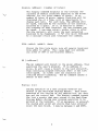
2.0
FLOPPY DISK DRIVER
The floppy driver (FLOPPY) is used to read and write from
the disk. The FLOPPY routine is only capable of
accessing preformatted Zilog diskettes. The driver
accepts a standard parameter vector as follows:
IY+0
IY+1
IY+2,IY+3
IY+4,IY+5
IY+6,IY+7
IY+8,IY+9
IY+10
IY+11,IY+12
IGNORED
REQUEST - TYPE OF ACTION NEEDED
DATA TRANSFER ADDRESS
DATA LENGTH IN BYTES
COMPLETION RETURN ADDRESS
ERROR RETURN ADDRESS
COMPLETION CODE
DISK ADDRESS
1
There are two valid requests for the floppy driver. They
are RDBIN(OAH), which will read data from the disk to the
area pointed to by the data transfer address, and
WRTBIN(OEH), which will write data from the area pointed
to by the data transfer address to the disk.
-~-\
;
If the request code is increased by one, then the driver
will return as soon as the request has been initiated,
permitting it to continue under interrupt control and
jumping to the completion return address after the
operation is complete. The routine at the completion
return address should act as an interrupt routine,
except that it should not execute an RETI. (A simple RET
should be used.) If the request code is used as given,
FLOPPY will return after the operation is completed.
In this case the completion return address is ignored.
If the data transfer length is not divisible by the sector
size, i.e., 128 bytes, it will be increased to the next
integral multiple of the sector size. Data will be written/
read from contiguous sectors. The length should be such
that the entire transfer will take place between the sector
where transfer starts and the end of the track., If this
limitation is not observed, a sector error will result on
a read operation and a permanent sector error will be
written on a write operation, resulting in certain sectors
being permanently inaccessible without reformatting the disk.
If an error occurs and the error return address is non-zero,
the routine at that address will be called. It: may take
whatever action is appropriate and return. If the address
is zero, the return would be as though there were no
error, except for the setting of the condition code.
Bit 7 of the condition code byte is set when the operation
is completed. Bit 6 is set to indicate that an error
occurred. The bottom six bits indicate which error it
was. Possible return codes are:
*Normal Return
(80H)
*Invalid Operation Request
(C1H)
*Not Ready - Disk is signalling a "Not Ready"
condition. (C2H)
.
*Disk is write protected.
(C3H)
\
*Sector Error - The Sector address in the
sector header did not agree with the sector
position. (C4H)
*Track Error - The Track address in the sector
header did not agree with the head position.
(C5H)
*CRC Error - The Cyclic Redundancy Checker (CRC)
indicates one or more data bits in error. (C6H)
''" *
^~S
The disk address at which the transfer is to begin is
represented as a track address from 0 to 77 decimal and a
sector address from 0 to 31 decimal. Additionally, three
bits indicating which of the two possible drives is to be
used for the transfer are carried as the top three bits of
the sector address.
(The drives are numbered 0 and 1.)
The track address is considered to be the most significant
part of the disk address (and therefore goes in IY+12),
while the sector address is considered to be the least
significant (and therefore goes in IY+11).
The entry point for the floppy driver is at location OBFDH,
3.0
TTY DRIVER
The TTY driver is used to read and write from the terminal,
On entry, IY should be pointing to a standard parameter
vector identical in format to that used by FLOPPY with the
exception, of course, of the last field (disk address)
which is ignored. Because of the differences of the
hardware devices in use, the operation of these routines
is necessarily different. The significance of parameters
to TTY is as follows.
There are four requests handled by the terminal driver.
These are RDBIN(OAH), WRTBIN(OEH), RDLIN(OCH), and
WRTLIN(IOH). The binary operations read or write the
specified length of data between the serial interface
and the block of memory beginning at the data transfer
address. No special characters are honored in binary
operations. No echoing is performed on RDBIN.
The RDLIN operation begins with the issuing of a prompt
character to the terminal and proceeds to input characters
to the data transfer area from the serial interface. All
input characters are echoed. Special line delete
(initialized by the 3K Monitor to "!", or ASCII 21H) and
character delete (initialized by the 3K Monitor to "@",
or ASCII 40H) are honored by this routine. A RDLIN
operation will terminate either on receipt of the
number of characters specified as the transfer length
or on receipt of a carriage return. The carriage return
will be echoed and the number of line feeds and null
characters specified in system RAM (see Section 5.0) will
be generated.
The WRITE operation also proceeds either for the number
of characters specified as the transfer length or until a
carriage return is encountered. After a carriage return is
encountered, the end of line sequence described above
(insertion of LF and NULs) is performed.
Both ASCII line operations return a count of the number of
characters actually transferred in the transfer length field.
If one is added to the request code, control will be
transferred to the completion return address after the
operation. The routine at this address should act as an
interrupt routine, except that it should not execute an RETI
(a simple RET should be used). If one is not added to the
request, TTY will return normally after the operation is
completed. In this case, the completion return address is
ignored.
If an error occurs and the return address is non-zero, the
routine at that address will be called. It may take whatever
action is appropriate and return. If the address is zero,
the return is normal, except for the setting of the completion
code.
Bit 7 of the completion code is set when the operation is
completed. Bit 6 is set to indicate that an error occurred.
The only error condition returned is Invalid Operation.
This will occur for request codes greater (arithmetically)
than those honored by TTY - lower request codes return
complete with no error but with no effect either.
The two line-edit commands interpreted by the TTY driver,
delete last character and delete current line, can be
changed from the Debug environment as follows:
To change the Delete last character command:
Set memory location OFC3H to the ASCII code
for the character desired. For example, to
make the "@" the character delete, one would
set the location to 40H.
,
To change the Delete current line command:
Set memory location OFC2H to the ASCII code
for the character desired. For example, to
make "!" the line delete, one would set the
location to 21H.
Note that both of the above addresses are in System RAM,
thus they are equivalent to addresses FFC3H and FFC2H when
looking at the user address space.
These characters are also changed when OS is bootstrapped
to its defaults, or by the Set command in RIO OS. This
means that if Debug is entered from OS, the characters may
not function in the same way.
The Development System interfaces to any terminal using a
standard 8-bit ASCII asynchronous transmission mode, with
or without parity, on RS-232 or 20 ma. current loop. The
interface will operate at the following speeds: 9600 baud,
4800 baud, 2400 baud, 1200 baud, 600 baud, 300 baud,
200 baud, 150 baud, 134.5 baud, 110 baud, 75 baud, 50 baud.
The entry point for the TTY driver is at location OBEEH.
4.0
DEBUG
ENVIRONMENT
4.1
DEBUG COMMANDS
In the following command descriptions, angle brackets ("<>")
are used to enclose descriptive names for the quantities
to be entered, and are not actually to be entered. Square
brackets ("[]") enclose optional quantities. Vertical bar
("I") indicates a choice may be made, e.g., A|B means either
A or B may be specified. Capital letters specify the minimum
acceptable abbreviation of a command. Parentheses are used
for grouping repetitive items. For example, a valid Display
command (see below) would be
D
1000
10
The PROM Debug environment offers the following
commands:
Break [[MR|MW|M1 [Address <nl>]] | [PR|PW [Port <n2>]]]
[Data <n3> [Mask <n4>]]
The Break command is used to program the Hardware
Breakpoint Module with the specified combination of
bus transactions that will terminate real-time
execution of the user's program and return control
to the Debug environment. Once in the Debug
environment, the user can employ Debug commands to
determine if his program is executing correctly, to
modify the program or CPU status, and then return
to the real-time execution of the user program via
a Go command. Upon occurrence of a hardware break
the entire status of the user's CPU is saved, allowing
execution to be resumed at a later date with the
entire status restored to its former condition.
The first parameter of the command specifies the
type of transaction that will generate the break.
Either Memory Read (MR), Memory Write (MW),
Instruction Fetch Cycle (Ml), Port Read (PR), or
Port Write (PW) can be specified. If no other
parameters are entered, the system will break on
the first occurrence of a transaction of the
specified type. For example, if the command B PW
is entered and the user program executed, the
system would break on the first Port Write to any
port.
_^
,
^-s
>
The second parameter specifies a memory or port
address. This parameter is entered only if it is
desired to specify a specified memory or port
address at which the Break will occur. For example,
the command B MR A 2001 will cause the system to
break when the first Memory Read from address 2001
occurs.
The third parameter allows the user to specify an
8-bit data field that must match the processor's
data bus for a break to occur. For example,
B MW D 32 would break if a 32H is written to any
memory location. The mask parameter can be used
with the data parameter, and causes specified bit
positions to be ignored if the mask bit is zero
for these positions.
.
If the Break command is issued with no parameters,
it clears any existing Breakpoint set-up.
Note that Breakpoints are disabled when executing
in Monitor mode.
.
COMPARE <nl> <n2> <n3>
!
The Compare command is used to compare the contents of
two blocks of memory. nl and n2 specify the starting
addresses of the two blocks, while n3 specifies the
number of bytes to be compared. If any locations of
the two blocks differ, the addresses and contents of
those locations are printed on the user's terminal.
"~~
.J
Display <address> [<number of bytes>]
The display command displays on the terminal the
contents of memory locations starting at the given
address, for the given number of bytes. If no
number of bytes is given, memory locations will be
displayed one at a time, with an opportunity to
change each byte. For each byte, the address will
be typed, followed by the contents of the location,
followed by a space. If it is desired to change
the contents of that location, the new contents can
be typed. A carriage return, either alone or after
the new contents, will cause the next sequential
location to be displayed. A "Q" (for Quit) followed
by a carriage return will terminate the command.
FILL <addrl> <addr2> <data>
Stores the data byte given into all memory locations
from addrl to addr2. This range must not include
any areas of ROM or non-existent memory.
GO
[<address>]
The Go command will branch to the given address, thus
executing the user's program. If no address is
given, Go will cause a branch to the last stored PC,
thus continuing program execution where it was last
interrupted. In either case all registers are
restored before branching. The Go command causes a
switch to User mode.
History [<n>]
During execution of a user program "events" are
stored in the Real-Time Storage Module. Each event
consists of the storing of the address bus, the data
bus and the control bus. The History command causes
the last n events that were stored in the Real-Time
Storage Module during user program execution to be
printed at the terminal. If no parameter is entered,
the system will print all events that have occurred
since the last break. n may be between 0 and OFFH.
The format for the output from the storage module is:
A D C
where:
A = 16-bit Address Bus
D = 8-bit Data Bus
C = 8-bit Control Bus Information
The control Bus information is interpreted as follows:
Bit
Bit
Bit
Bit
Bit
Bit
Bit
Bit
0
1
2
3
4
5
6
7
-
First even stored marker
Halt acknowledge (Inverted)
Ml
Bus acknowledge
MW
MR
PW
PR
Interrupt Status
The Interrupt Status command displays the state of
the interrupt enable flip-flop when the user program
was executing.
0 for interrupts disabled
1 for interrupts enabled
'
!
The user can then change the status by entering a
0 (DI) or a 1 (El) or he may terminate the command
with a "0" or carriage return.
Jump [<address>]
The Jump command will branch unconditionally to the
given address. Registers are restored before
branching; however, unlike the Go command, the
transition to User mode is not made. If no address
is given, Jump will cause a branch to the last
stored PC.
Move <dest> <source> <n>
The Move command is used to move the contents of a
block of memory from the source address specified by
<source>, to the destination address specified by
<dest>. n is the length of the block to be moved.
There are no restrictions on <source>, <dest>, or n,
except that they be positive integers, and that the
blocks be bound within the 64K bytes addressed by
the Z80 CPU.
s
Next [<n>]
The Next command will cause the execution of the
next n machine instructions, startinq at the current
PC, and display all registers after each instruction
execution. If n is not given, 1 is assumed. After a
NEXT command, hitting successive carriage returns
will cause execution and tracing of the following
instructions.
Port
<n>
An input is done from port n and the value is displayed on
the terminal. The user can then output to this port by
entering a hex value followed by a carriage return.
Pulse [[MRlMWlMI [Address <nl>]] I [PR|PW [Port <n2>]]]
[Data <n3> [Mask <n4>]]
The Pulse command is exactly like the Break command;
however, program execution is not halted when the
specified condition occurs. Instead,, a sync pulse
is generated at the BNC co-axial connector at the
rear of the Development System cabinet.
Quit
This command will cause the user to leave the Debug
environment and return to OS or to another specified
routine (see Section 4.2).
If OS has not been
loaded, the Quit command will not be interpreted and
the system will respond with a "?".
Register [<register name>|IM|AD]
The Register command permits the contents of the
indicated register, interrupt mode flag or address
flag to be examined and modified. If no register name
is given, all registers will be displayed on one
line. If a register name is given, individual
registers will be displayed starting with the
one given. The register name will be typed
followed by its contents, followed by a space.
If it is desired to change the contents of that
register the new contents can be typed. A
carriage return, either alone or after new contents,
will cause the next register to be displayed. If
no more registers are desired, a "0" (for Quit)
should be entered, followed by a carriage return.
This will terminate the command. The contents of
the address offset flag (AD) and the User Interrupt
Mode (IM) can also be displayed and modified in
this same manner.
The registers being examined and modified are
memory locations in which the indicated registers
are saved at the start of the program and at each
breakpoint, and from which they are restored at
each Go command.
The sequence in which the registers are displayed
when they are stepped from one to the next is:
IM, A, B, C, D, E, F, H, L, I, A 1 , B 1 , C 1 , D 1 , E 1 ,
F 1 , H 1 , L 1 , IX, IY, PC, SP, ADR.
I
Set <address> <data> <data> <data> ...
'
The Set command stores the given data words into
sequential memory locations starting at the given
address.
Trace [MR] [MW] [PR]
[PW]
The Trace command is used to specify which types
of bus transactions will be stored in the Real-Time
Storage Module. The Trace command will accept from
one to four of these parameters, in any order.
If no parameters are specified, the command resets
the Trace and no transactions will be stored. At
power-on the system automatically specifies a Trace
of all four parameters.
All of the above commands may be abbreviated to their
first letter, or may have the command spelled out to any
desired length. The first character typed on a new line
will be taken as the key to which command is being
invoked. If a command is not understood, a "?" will be
typed and a new command requested. All numbers may be
entered in free-form hex, with leading zeros oiritted. If
more than four hex digits are entered, the last four will
form the number used. All fields are blank delimited.
10
4.2
DEBUG INTERFACE
There are two ways in which an external routine can interface
with the PROM Debug package. With either, a flag is set and
a return address is stored in an associated location.
The first way is to make a call into the Debug environment,
thus passing control to the Debug command interpreter until
a Quit command is issued. This is done by setting bit 5 of
location OFC4H (BRKFLG) in system RAM (FFC4H in user
space), storing the return address at locations OFB5H,
OFB6H (FFB5H, FFB6H in user space) (EXTRET), and jumping to
the Debug command interpreter at OBFAH.
The second method is used when an external routine is used to
handle breakpoints. If bit 7 of OFC4H (FFC4H in user space)
is set, the occurrence of a breakpoint will cause a jump to
the location stored at OFC5H, OFC6H (FFC5H, FFC6H in user
space) (BRKRTN).
11
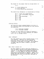
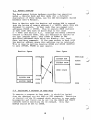
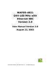
4.3
MEMORY MAPPING
The Development System hardware provides two operating
modes — Monitor mode and User mode (for a detailed
description of these modes, see the Z80 Development System
Hardware User's Manual).
When in Monitor mode the Monitor and system RAM is mapped
into the bottom of memory address 0 -> OFFFH, where they are
designed to execute.
In User mode they are mapped into
addresses FOOOH -> FFFFH. Thus to execute PROM routines
in User mode they must be moved down to the range
0 -> FFFH (see Section 4.1).
Although the Debug commands
execute in Monitor mode, they are designed to operate on
the user address space, thus 1000H is added to the
specified addresses when using the Display, Get, Load,
Save, and Move commands.
If the user wishes to deal with
the monitor address space this addition can be inhibited.
This is done by setting location OFD8H and OFD9H (ADRFLG)
to zero (FFD8H, FFD9H in user space).
Monitor Space
User Space
FFFF=64K
FFFF=64K
SYSTEM RAM
FCOOH
SYSTEM PROM
FOOOH
USER SPACE
SYSTEM RAM
SYSTEM PROM
OOOH
4.4
EXECUTING A PROGRAM IN USER MODE;
To execute a program in User mode, it should be
from the debugger via the LOAD or GET commands.
is started via the GO command which switches to
Breakpoints and traces can be set via the BREAK
commands before executing the GO command. Note
ADRFLG should be set to 1000H.
12
loaded
Execution
user mode.
and TRACE
that
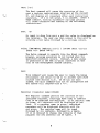
4.5
EXECUTING PROGRAMS IN MONITOR MODE
The following section describes how to prepare and debug
a program to be executed in Monitor mode.
After assembling the program, a procedure file must be
created. With the RIO system this is done by linking the
assembled object file.
When using the GET command from the Debugger,. ADRFLG
(described in 4.2) should be set to zero so that no
offset is added to the load address. If this flag is
not reset, then the program must be moved down 10ÖOH
bytes after loading.
«
Once a procedure file has been created it is executed from
the executive by simply typing its name:
Examples:
RIO System
V_x
%ASM MONITOR.PROGRAM
PASS 1 COMPLETE
0 ASSEMBLY ERRORS
ASSEMBLY COMPLETE
%LINK $=4000 MONITOR.PROGRAM
LINK COMPLETE
%MONITOR.PROGRAM
execution begins
Non-Maskable Interrupt (NMI) and RST 38 may be trapped
by a user program. The variables NMIDSP (system RAM
address EEEH) and RSTDSP (system RAM address EECH)
specify the addresses to branch to on these conditions.
All registers are preserved and the address at which
the condition occurred is on the stack. Both of these
variables are initialized to 0 on reset.
13
4.6
DEBUGGING A PROGRAM WHICH IS INTENDED TO RUN
IN MONITOR MODE
The DEBUG services of the Development System are all
designed for use with programs running in the User mode.
Thus, it is necessary to run in User mode while debugging
This can be accomplished by using the following procedure
after the program has been prepared for execution in the
Monitor mode as described above:
1.
Move Monitor program into dynamic memory (User
mode address 0)
,
>M 0 FOOO COO
2.
Set desired breakpoints and trace mode
>B Ml A 1C80
>T MR MW
3.
NOTE: The RIO system sizes memory via execution of
a memory write followed by a memory read. Thus, to
prevent the sizing routine from causing a break,
Ml should be specified instead of MR.
•I
I
Transfer control to the copy of the Monitor program
in User memory
>G 0
NOTE: This places the system in User mode and is
equivalent to a system Reset. It is, therefore,
necessary to supply a speed recognition character
(CR) and a bootstrap command (CR or OS) , after which
the system will be at the executive level, but
executing in User mode.
4.
The file name would then be typed thus beginning
execution of the program.
At this point, the breakpoint set in step 2 above
would be encountered and the system would return
to the Monitor mode.
BREAK AT x x x x
14
5.0
SYSTEM PARAMETERS
There are several system parameters which are accessible
to the user. They are:
NULLCT — Null Count
(FBFH)
In this location, the number of null characters
which will be inserted after a carriage return
(and whatever number of line feeds which are
also inserted) is stored. Modifying the null
count is the means of adapting the MCS to the
carriage return delays of various terminals.
NULLCT is initialized to 0.
LFCNT — Line Feed Count
(FCOH)
In this location, the number of line feeds which
will be inserted after a carriage return is
stored. Modifying the line feed count permits
automatic multiple spacing. LFCNT is initialized to 1
PROMPT — Prompt Character (FC1H)
In this location, the character output by the
TTY routine before reading a line from the
terminal is stored. Modifying the prompt
character permits various levels of interactive
software to identify themselves in each command
query. Prompting can be effectively eliminated
by setting this location to a null character
(ASCII 0). PROMPT is initialized to '>'.
LINDEL — Line Delete
(FC2H)
In this location, the character interpreted by
the TTY routine as a line delete is stored.
When it is encountered in the ASCII input
stream from the terminal, this routine purges
the buffer and continues reading the input
stream. LINDEL is initialized to 21H.
CHRDEL — Character Delete
(FC3H)
In this location, the character interpreted by
the TTY routine as a character delete is
stored. When it is encountered in the ASCII
input stream, the last character entered is
purged from the input buffer. Multiple character
deletes may be used to delete the last "n"
characters entered. CHRDEL is initialized to 40H.
BRKFLG — Breakpoint Flag
(FC4H)
Bit 5 of this location is used to determine the
return address for the QUIT command. Bit 7 is
used to signal the existence of an external
breakpoint handler (see Section 4.2).
BRKFLG is
initialized to 0.
15
BRKRTN — Breakpoint Return (FC5H, FC6H)
This location is used with BRKFLG to make use of
an external breakpoint handler (see Section 4.2).
BRKRTN is initialized to 0.
EXTRET — External Return (FB5H, FB6H)
This location is used with BRKFLG when calling
the Debug command interpreter (see Section 4.2).
NMIDSP — Non maskable interrupt Dispatch (EEEH, EEFH). The
contents of this location specifies the address to branch
to on Non-Maskable Interrupt (NMI). NMIDSP is initialized
to 0.
RSTPSP — RST 38 dispatch (EECH, EEDH). The contents of this
location specify the addresses to branch to when a RST 38
is executed. RSTDSP is initialized to 0.
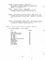
There are several eauat.es used by the system.
ZDS SYSTEM HARDWARE I/O PORT ADDRESS
PORT
ADDRESS
USART DATA
USART CONTROL/STATUS
BAUD RATE DETECTION
CTC CHAN 0
CTC CHAN 1
CTC CHAN 2
CTC CHAN 3
REAL TIME STORAGE MODULE
BREAKPOINT
SYSTEM RESET
SYSTEM STATUS
DISK DATA
DISK CONTROL
DISK STATUS
16
P4
F5
FF
FO
Fl
F2
F3
FC
FB
FD
FE
F8
F9
FA
They are
^—^
\
^/
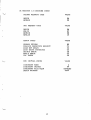
3K MONITOR I/O ROUTINE CODES
FLOPPY REQUEST CODE
VALUE
OA
OE
RDBIN
WRTBIN
TTY REQUEST CODE
VALUE
OA
OC
OE
10
RDBIN
RDLIN
WRTBIN
WRTLIN
ERROR CODES
VALUE
NORMAL RETURN
INVALID OPERATION REQUEST
DISK NOT READY
DISK WRITE PROTECTED
SECTOR ERROR
TRACK ERROR
CRC ERROR
CPU INITIAL STATE
80
Cl
C2
C3
C4
C5
C6
VALUE
2
OF
ENABLED
ODOO
INTERRUPT MODE
INTERRUPT VECTOR
INTERRUPT FLIP/FLOP
STACK POINTER
17
DOCUMENT CHANGE NOTICE
Zilog
DATE: 10-25-78
DCN NUMBER: E3-3002-01, Rev. A
PUBLICATION NUMBER: 03-3002-01, Rev. A
TITLE: ZDS-1/25, 1/40 PROM User Manual
PREVIOUS DCN'S, BY NUMBER: None
EFFECTIVE DATE: 10-25-78
This Document Change Notice provides an addendum page for •
the publication specified above. This addendum will remain
in effect for subsequent releases unless specifically
amended by another DCN or superseded by a publication
revision. The attached page is to be added at the back of
the manual:
ADDENDUM, page 19
Changes to text or illustrations are indicated by a vertical
line to the left of the change.
NOTE; Please file this DCN at the back of the manual to
provide a record of changes.
CF-1017-01A
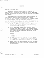
ADDENDUM
FOR ZDS-1/40 USERS ONLY:
The Zilog Analyzer Program (ZAP) is supplied to
ZDS-1/40 users to replace the capability of the PROM DEBUG
Program as described in Section 4 of the ZDS-1/25, 1/40 PROM
User Manual.
The capability of the ZAP Program (see discussion in
the Z80A CPU Emulator Module Software User's Guide,
03-0110-01, Rev. A) makes it unnecessary for a ZDS-1/40 user
to concern himself with the PROM DEBUG software.
If the PROM DEBUG software is used on the ZDS-1/40, the
following discrepancies will become obvious:
1) The GO and NEXT Commands do not work: If they are
executed, the system will stop, and a bootstrap
procedure will be necessary.
2) In any PROM DEBUG command that accesses memory
(DISPLAY, SET, MOVE, or FILL), the address used is
1000H lower than the address entered in the command.
This problem may be eliminated by setting the AD
Register to zero.
Example:
>R AD
AD 1000
0
3) The PORT Command can do I/O only to ports FFOOH
through FFFFH, e.g., The B Register of the BC pair
in an OUT (C),A Instruction is always set to OFFH.
4) BREAK, PULSE, and TRACE Commands set with the PROM
DEBUG program are lost if the user returns to the
ZAP environment.
E3-3002-01, Rev. A
-19-
10/25/78
c
r
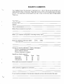
READER'S COMMENTS
Your feedback about this document is important to us: only in this way can we ascertain your
needs and fulfill them in the future. Please take the time to fill out this questionnaire and return
it to us. This information will be helpful to us, and, in time, to the future users of Zilog systems.
Thank you.
Your Name:.
Company Name:.
Address:
Title of this document:.
What software products do you have?_
What is your hardware configuration (including memory size)?_
Does this publication meet your needs?
If not, why not?
ÖYes
G No
How do you use this publication? (Check all that apply)
I | As an introduction to the subject?
0 As a reference manual?
1 | As an instructor or student?
How do you find the material?
Excellent
Technicality
D
Organization
I I
Completeness
I I
Good
D
I I
I I
Poor
D
I I
I I
What would have improved the material?
Other comments, suggestions or corrections:.
If you found any mistakes in this document, please let us know what and where they were:
First Class
Permit No. 475
Cupertino
California
95014
Business Reply Mail
No Postage Necessary if Mailed in the United States
Postage Will Be Paid By
Zilog
Software Department Librarian
10460 Bubb Road
Cupertino, California 95014
Zilog
10340 Bubb Road
Cupertino, California 95014
Telephone (408) 446-4666
TWX 910-338-7621
03-3030-01
Printed in USA