1
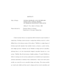
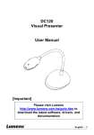
DENTAL EQUIPMENT
High Speed Automatic Spindle User’s Manual
READ AND UNDERSTAND ALL INSTRUCTIONS
BEFORE PROCEEDING
Tools included with the High Speed Spindle
Allen Wrenches
1/8, 3/32, 5/64
Open End Wrench
P/N F652
5421 Commercial Drive
Huntington Beach, CA 92649
www.fosterdental.com
Collet Stop
Adjustment Tool
P/N F650
Collet Wrench
P/N F155
Optional
Spanner Tool
P/N F651
Tel 800.654.4519
Fax 714.898.6013
Mounting Tubes
Spindle Features
Tool
Collet
Pulley
Brake
Collet Wrench
Handle
Figure 1.
Collet Body
12
1
11
Operation – To open the collet and change tools, move
the clutch handle counterclockwise to the right. This will
disengage the clutch, stop the rotation of the tool, and open
the collet. Tools can now be removed and replaced while the
machine is running.
See figure 1
2
10
9
3
Removing, Adjusting, or Changing the Collet
The collet (p/n F106) will wear under normal spindle
operation. The most common symptom of a worn out
collet is the tool slipping because it is not being gripped
firmly by the collet. A worn collet may also bind the
spindle so that it will not turn freely. This will cause overheating and slippage of the clutch.
To adjust the existing collet or install a new collet:
Operating
Position 8
4
Open
Position
5
7
6
Open Collet
Caution: NEVER close the collet without a tool
inserted. This will cause the spindle to bind and stop
and could damage the spindle.
1. Move the clutch handle to the open position.
(see figure 1). Remove the tool.
2. Remove the collet wrench from the end of the handle (see
figure 2). It may be necessary to loosen the set screw that
secures the handle with a 3/32” hex wrench in order to
remove the tool.
Figure 2.
Collet Wrench
Collet Adjustment Screw
4. Insert the collet wrench into the open jaws of the collet and
unscrew counterclockwise. For added leverage you may insert
a bur shank into the hole of the collet wrench to create a “T”
handle. Remove the collet completely.
5. Behind the collet is the collet stop adjustment screw (see
Illustration 1). To adjust a worn collet for additional wear,
turn the collet stop adjustment screw clockwise to allow the
collet to retreat farther into the collet body to grip the tool
shank. Use the hex end of the Collet Stop Adjusting Tool (see
Illustration 4) to turn the Collet Stop Screw.
6. Turn the Collet Stop Screw approximately 1/4 turn,
reinstall the Collet, insert a tool and check the fit. It may be
necessary to adjust a few times to get the fit just right. The
collet needs to open just enough to allow the tool to be easily
inserted and removed.
See figure 3 for position and fit of collet.
Set Screw
Illustration 1. (cut-away view)
Collet Stop Adjustment Screw
Collet
Collet
Figure 3.
1.5 - 2mm
Operating Position
.5 mm
2 - 2.5mm
Closed Without Tool
Open Position
Note: One symptom of a worn collet is it will begin to receed back into the spindle collet body.
Collet Stop Adjustment Tool
The Collet Stop Adjustment Tool (P/N F650) was
designed to adjust and clear grinding debris from the
collet stop screw. The hex end can be inserted into
the stop screw while it’s still in the shaft so that
adjustments can be made. The drill end is used to clear
grinding debris that has built up in the hex socket.
See Illustrations 3.
These cut-away illustrations demonstrate the location and
adjustment of the collet stop screw.
Illustration 2. Location of Collet Stop Screw
Illustration 3. Showing adjustment tool removing debris
Collet Stop Adjustment Tool (P/N F650)
Illustration 4. Showing adjustment tool in Collet Stop screw
Removing The Spindle Brake
If the collet stop screw becomes stuck in the shaft it will be
necessary to hold the shaft to turn the screw. Follow these
steps:
1. With the collet removed and the handle in the
closed position, using the spanner tool (optional P/N
F651), remove the brake by unscrewing clockwise.
See figure 4.
Figure 4.
Brake
Turn Clockwise
To Remove
2. With the brake removed, slip off the collet body and
compression spring which is located inside the collet body.
3. Hold the shaft with the 3/8” end of the Open End
Wrench and loosen the Collet Stop Screw with the
Collet Stop Adjustment Tool. If needed, insert a 3/32”
tool shank into the hole of the adjustment tool to create
a “T” handle.
Collet Maintenance
The collet should be removed and cleaned on a weekly basis to prevent it from becoming stuck. Once
removed you may use solvent to clean the collet, but be sure to dry the collet of solvent and apply grease or Vaseline
on the threads of the collet before reinstalling. Do not use oil on the collet. NEVER oil any part of the spindle.
4
5
6
F939
F940
F941
F944
F945
T013
T012
T015
T014
F718
F835
33
34
35
36
37
38
39
40
41
42
43
Bearing for Front Case
Bearing Disc Spring
Screw 10/32 x 1-1/2”
Washer
Mount Tube
Rubber Bushing
Screw 6/32 x 1/4”
Washer
Plug
Clutch Spring
Push Rod
Special Set Screw
Mount Tube Assembly Complete
F938
32
Spindle Housing
Hole Cover
T011
F936
31
Spindle Housing Assembly Complete
F935
30
Cam Sleeve
Screw 10/32 x 1/2” Flat Head
F900
F934
29
Front Case Assembly Complete
F932
28
Handle Sleeve
F800
F931
27
Handle
Cam
8
Rear Case Assembly Complete
F930
7
F700
F928
26
PART NO. DESCRIPTION
3
25
REF. NO.
2
ASSEMBLIES
1
6
42
39
38
41
40
38
30
9
10
FOR ADDITIONAL INFO GO TO WWW.FOSTERDENTAL.COM
41
28
25
23
HIGH SPEED SPINDLE ASSEMBLY - EXPLODED VIEW
11
40
38
39
38
31
29
33
26
34
12
24
32
35
43
14
36
13
27
15
37
43
F841
F844
F845
15
16
17
16
F927
F840
14
24
F838
13
F155
F837
12
23
F836
11
F850
F725
10
22
F720
9
F849
F716
8
21
F715
7
F848
F714
6
20
F712
5
F846
F710
4
19
F707
3
F106
F703
18
F701
2
20
19
17
18
Set Screw 10/32 x 3/16”
Collet Wrench
Blank Tool
Brake
Collet Body
Compression Spring
Collet 3/32”
Collet Adjusting Screw
Front Shaft
Front Case Bolt
Spacer, Outer Front Spacer, Inner Front 22
21
Case, Front Bearing Assembly
Front Clutch
Rear Clutch with Lining
Case, Rear Bearing Assembly Spacer, Inner Rear Spacer, Outer Rear Bearing for Rear Case
Rear Shaft
Rear Case Nut
Low Speed Pulley – Large
High Speed Pulley – Small
Pulley Nut
PART NO. DESCRIPTION
1
REF. NO.