Transcript
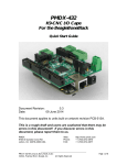
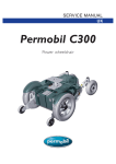
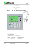
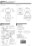
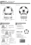
Quick Start Guide
F651-12C1 12.1" Liquid Crystal Display TV
This guide is designed as a reference to help you start using your LCD TV quickly. Please refer to the User's Manual for more detailed installation and safety instructions.
Front View & Rear View
Channel
select
Menu
MENU
CH -
Speaker
Volume
adjust
Power
CH +
Getting Started
VOL -
Placing the Clock and Thermometer/Hygrometer
Source
VOL +
SOURCE
Clock
Thermometer/Hygrometer
1. Turn the clock so that the screw points to
the 11 o'clock position as shown (A).
2. Turn the clock face clockwise as shown (B).
The clock is locked into place.
1. Turn the Thermometer/Hygrometer so that
the screw points to the 5 o'clock position
as shown (A).
2. Turn the Thermometer/Hygrometer face
clockwise as shown (B).
The Thermometer/Hygrometer is locked
into place.
Speaker
Power indicator LED
Remote IR sensor
Thermometer/Hygrometer
Clock
Removing the Clock and Thermometer/Hygrometer
Clock
05
0
50
X
60
50
70
40
80
90
IX
10
0
-1
45
-10
0
20 30
10
0
0
13
0
%
50
HYGROMETER
80 90 10
20
0
-2
70
V III
50 60
12
0
IIII
V
CF
VI
25
THERMOMETER
30
40
110
III
15
40
40
100
20
II
QUARTZ
VII
35
ANT
DC-IN
1. Hold the Thermometer/Hygrometer and twist
it counterclockwise as shown to unlock it.
2. Remove the Thermometer/Hygrometer.
1. Hold the clock and twist it counterclockwise
as shown to unlock it (A).
2. Remove the clock (B).
HEADPHONE AV IN
DC-IN
Antenna/Cable TV
Thermometer/Hygrometer
20
10
I
30
XII
10
XI
30
55
Note: Place your fingers as shown to avoid
damage to the LCD panel.
AV
Headphone jack
Making Connections
A/V and Channel Setup
Connecting to Antenna/Cable TV
Selecting A/V Sources
Antenna
ANT
DC-IN
1. Connect one end of the VHF/UHF
(Antenna) or CATV cable to ANT Jack
(VHF/UHF IN Jack) on the back of the
TV.
2. Connect the other end of the VHF/UHF
(Antenna) or CATV cable to the Antenna
or CATV socket.
HEADPHONE AV IN
ANT jack
(VHF/UHF IN Jack)
Antenna/CATV
coaxial cable
1. Make sure your TV is turned on and a
device such as a DVD player is connected.
2. Press the SOURCE button on the
control panel to select different source signals.
TV channel number, AV or AVs appear on the screen.
Note : AVs only appears on the screen when
S-Video is connected.
TV
Connecting to a VCR, VCD, DVD Player, or Video Game Console
MENU
1. The illustration presented
here shows you how to
connect your TV to a
VCR, VCD, DVD
player or video
game console.
VOL -
VOL +
SOURCE
AV
VCD
DVD
Video game
console
ANT
B
R
W
Y
2. The cables are
color-coded (black,
red, white, and
B R W Y
yellow). Connect
each color-coded
S-Video
cable to the
connector
appropriate
connector on your
AV connectors
4-IN-1 A/V cable
device.
DC-IN
HEADPHONE AV IN
Connecting the Power Adapter
Power outlet
Power cord
DC-IN
CH +
VCR
4-IN-1 A/V jack
ANT
CH -
HEADPHONE AV IN
DC-IN
Power adapter
Copyright 2005, Hannspree, Inc. All rights reserved.
1. Connect the power cord to the power
adapter as illustrated.
2. Plug the power adapter connector into
the DC-IN input jack on the rear panel
of the TV.
3. Insert the three-pronged plug at the
other end of the power cord into a
power outlet.
Note :
Images are for illustration only and may
vary by model or region.
Auto Channel Setup
Please follow the instructions by using the control panel.
1. Press the MENU button to enter the OSD menu.
2. Use the CH - button to select "TV".
3. Press the VOL + button to enter the TV setting.
4. Press the CH - button until the "Auto Program" feature is selected.
5. Press the VOL + button to begin "Auto Program".
6. Your television will begin automatically memorizing the available channels.
Auto Program
TV
Auto-Programming
093.84 MHz
1
6%
Return : MENU
MAD-001308