1
20F216-00 E5 – 2014-01-14
User Manual
F216 - 3U CompactPCI®
Octal UART
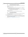
Configuration example
F216 - 3U CompactPCI® Octal UART
F216 - 3U CompactPCI® Octal UART
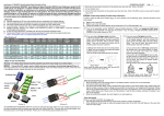
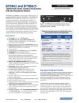
The F216 is an octal UART I/O board based on 3U CompactPCI®. Two UART
controllers provide four full-duplex serial channels each. The physical layers are
integrated on the board: each of the eight channels can be individually configured as
single-ended RS232 or differential RS422 or RS485. The default setting is RS422.
The UART controller supports high data rates up to 921 600 bit/s, depending on the
physical interface type. Its register set is fully 16550D compatible, even with larger,
60-byte FIFOs.
Each channel of the F216 has its own 500V isolation, with all ports being available
on one 78-pin D-Sub connector. An adapter cable is also available to spread the 78pin connector to eight standard 9-pin D-Sub connectors.
The F216 is designed for use in rugged environments. For example, all components
are specified for an operating temperature of -40 to +85°C. The card easily expands
CompactPCI® systems by an additional eight UARTs on 4 HP where the CPU does
not provide enough COM interfaces.
MEN Mikro Elektronik GmbH
20F216-00 E5 – 2014-01-14
2
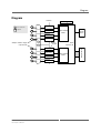
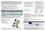
Diagram
Diagram
Isolation
Front connector
Options
F
Line Drivers
F
Line Drivers
F
Line Drivers
F
Line Drivers
F
Adapter cable to single 9‐pin D‐Subs
78‐pin D‐Sub
F
Line Drivers
F
Line Drivers
F
Line Drivers
F
Line Drivers
MEN Mikro Elektronik GmbH
20F216-00 E5 – 2014-01-14
RS232/
422/485
Quad 16550
UART
Serial
Flash
FPGA
Cyclone™ III
Quad 16550
UART
CompactPCI J1
F
State Savers
3
Technical Data
Technical Data
UART Interfaces
•
•
•
•
•
•
•
•
•
•
Eight RS232/RS422/RS485 UARTs
Software-configurable
Default at start-up: RS422, can be customized through non-volatile state saver
Two 16Z125_UART controllers with four UARTs each
Data rates:
- Up to 921,600 bit/s with RS422/RS485
- Up to 230,400 bit/s with RS232
60-byte transmit/receive buffer
Handshake lines: full support with RS232
Full-duplex operation with RS422, half-duplex operation with RS485
Isolation between channels: 500V
Accessible on front-panel 78-pin D-Sub connector
Miscellaneous
• Four status LEDs at front panel
- One status LED to signal FPGA configuration (UARTs ready)
- Three user LEDs, FPGA-controlled by 16Z034_GPIO controller
CompactPCI® Bus
• Compliance with CompactPCI® Core Specification PICMG 2.0 R3.0
• Peripheral slot
• V(I/O): +3.3V (+5V tolerant)
Electrical Specifications
• Supply voltage/power consumption:
- +5V (-3%/+5%), 430mA
- +3.3V (-3%/+5%), 170mA
Mechanical Specifications
• Dimensions: conforming to CompactPCI® specification for 3U boards
• Front panel: 4HP with ejector
• Weight: 182g
MEN Mikro Elektronik GmbH
20F216-00 E5 – 2014-01-14
4
Technical Data
Environmental Specifications
• Temperature range (operation):
- -40..+85°C (qualified components)
- Airflow: min. 1m/s
• Temperature range (storage): -40..+85°C
• Relative humidity (operation): max. 95% non-condensing
• Relative humidity (storage): max. 95% non-condensing
• Altitude: -300m to + 3,000m
• Shock: 15g/11ms
• Bump: 10g/16ms
• Vibration (sinusoidal): 2g/10..150Hz
• Conformal coating on request
MTBF
• 96,149h @ 40°C according to IEC/TR 62380 (RDF 2000)
Safety
• PCB manufactured with a flammability rating of 94V-0 by UL recognized manufacturers
EMC
• Conforming to EN 55022 (radio disturbance), IEC1000-4-2 (ESD) and
IEC1000-4-4 (burst)
Software Support
• Driver software for Windows®, Linux, VxWorks®, QNX®
• For more information on supported operating system versions and drivers see
online data sheet.
MEN Mikro Elektronik GmbH
20F216-00 E5 – 2014-01-14
5
Product Safety
Product Safety
!
Electrostatic Discharge (ESD)
Computer boards and components contain electrostatic sensitive devices.
Electrostatic discharge (ESD) can damage components. To protect the board and
other components against damage from static electricity, you should follow some
precautions whenever you work on your computer.
• Power down and unplug your computer system when working on the inside.
• Hold components by the edges and try not to touch the IC chips, leads, or circuitry.
• Use a grounded wrist strap before handling computer components.
• Place components on a grounded antistatic pad or on the bag that came with the
component whenever the components are separated from the system.
• Store the board only in its original ESD-protected packaging. Retain the original
packaging in case you need to return the board to MEN for repair.
MEN Mikro Elektronik GmbH
20F216-00 E5 – 2014-01-14
6
About this Document
About this Document
This user manual is intended only for system developers and integrators, it is not
intended for end users.
It describes the hardware functions of the board, connection of peripheral devices
and integration into a system. It also provides additional information for special
applications and configurations of the board.
The manual does not include detailed information on individual components (data
sheets etc.). A list of literature is given in the appendix.
History
Issue
Date
E1
First edition
2008-08-07
E2
Minor errors corrected; Windows package available;
baud rate parameter values for Linux and VxWorks corrected; 5V V(I/O) added
2008-12-12
E3
5V V(I/O) corrected (tolerant, not universal board); note
added to chapter 2.2.4.6
2009-03-19
E4
Added note in chapter 2.2.4.2
2010-12-13
E5
Changes made to chapter 2.2.4.2 UART ports
2014-01-13
MEN Mikro Elektronik GmbH
20F216-00 E5 – 2014-01-14
Comments
7
About this Document
Conventions
This sign marks important notes or warnings concerning the use of voltages which
can lead to serious damage to your health and also cause damage or destruction of
the component.
!
italics
bold
monospace
This sign marks important notes or warnings concerning proper functionality of the
product described in this document. You should read them in any case.
Folder, file and function names are printed in italics.
Bold type is used for emphasis.
A monospaced font type is used for hexadecimal numbers, listings, C function
descriptions or wherever appropriate. Hexadecimal numbers are preceded by "0x".
comment
Comments embedded into coding examples are shown in green color.
hyperlink
Hyperlinks are printed in blue color.
The globe will show you where hyperlinks lead directly to the Internet, so you can
look for the latest information online.
IRQ#
/IRQ
Signal names followed by "#" or preceded by a slash ("/") indicate that this signal is
either active low or that it becomes active at a falling edge.
in/out
Signal directions in signal mnemonics tables generally refer to the corresponding
board or component, "in" meaning "to the board or component", "out" meaning
"coming from it".
Vertical lines on the outer margin signal technical changes to the previous issue of
the document.
MEN Mikro Elektronik GmbH
20F216-00 E5 – 2014-01-14
8
About this Document
Legal Information
Changes
MEN Mikro Elektronik GmbH ("MEN") reserves the right to make changes without further notice to any products
herein.
Warranty, Guarantee, Liability
MEN makes no warranty, representation or guarantee of any kind regarding the suitability of its products for any
particular purpose, nor does MEN assume any liability arising out of the application or use of any product or
circuit, and specifically disclaims any and all liability, including, without limitation, consequential or incidental
damages. TO THE EXTENT APPLICABLE, SPECIFICALLY EXCLUDED ARE ANY IMPLIED
WARRANTIES ARISING BY OPERATION OF LAW, CUSTOM OR USAGE, INCLUDING WITHOUT
LIMITATION, THE IMPLIED WARRANTIES OF MERCHANTABILITY AND FITNESS FOR A
PARTICULAR PURPOSE OR USE. In no event shall MEN be liable for more than the contract price for the
products in question. If buyer does not notify MEN in writing within the foregoing warranty period, MEN shall
have no liability or obligation to buyer hereunder.
The publication is provided on the terms and understanding that:
1. MEN is not responsible for the results of any actions taken on the basis of information in the publication, nor
for any error in or omission from the publication; and
2. MEN is not engaged in rendering technical or other advice or services.
MEN expressly disclaims all and any liability and responsibility to any person, whether a reader of the publication
or not, in respect of anything, and of the consequences of anything, done or omitted to be done by any such person
in reliance, whether wholly or partially, on the whole or any part of the contents of the publication.
Conditions for Use, Field of Application
The correct function of MEN products in mission-critical and life-critical applications is limited to the
environmental specification given for each product in the technical user manual. The correct function of MEN
products under extended environmental conditions is limited to the individual requirement specification and
subsequent validation documents for each product for the applicable use case and has to be agreed upon in writing
by MEN and the customer. Should the customer purchase or use MEN products for any unintended or
unauthorized application, the customer shall indemnify and hold MEN and its officers, employees, subsidiaries,
affiliates, and distributors harmless against all claims, costs, damages, and expenses, and reasonable attorney fees
arising out of, directly or indirectly, any claim or personal injury or death associated with such unintended or
unauthorized use, even if such claim alleges that MEN was negligent regarding the design or manufacture of the
part. In no case is MEN liable for the correct function of the technical installation where MEN products are a part
of.
Trademarks
All products or services mentioned in this publication are identified by the trademarks, service marks, or product
names as designated by the companies which market those products. The trademarks and registered trademarks
are held by the companies producing them. Inquiries concerning such trademarks should be made directly to those
companies.
Conformity
MEN products are no ready-made products for end users. They are tested according to the standards given in the
Technical Data and thus enable you to achieve certification of the product according to the standards applicable in
your field of application.
MEN Mikro Elektronik GmbH
20F216-00 E5 – 2014-01-14
9
About this Document
RoHS
Since July 1, 2006 all MEN standard products comply with RoHS legislation.
Since January 2005 the SMD and manual soldering processes at MEN have already been completely lead-free.
Between June 2004 and June 30, 2006 MEN’s selected component suppliers have changed delivery to RoHScompliant parts. During this period any change and status was traceable through the MEN ERP system and the
boards gradually became RoHS-compliant.
WEEE Application
The WEEE directive does not apply to fixed industrial plants and tools. The compliance is the responsibility of the
company which puts the product on the market, as defined in the directive; components and sub-assemblies are
not subject to product compliance.
In other words: Since MEN does not deliver ready-made products to end users, the WEEE directive is not
applicable for MEN. Users are nevertheless recommended to properly recycle all electronic boards which have
passed their life cycle.
Nevertheless, MEN is registered as a manufacturer in Germany. The registration number can be provided on
request.
Copyright © 2014 MEN Mikro Elektronik GmbH. All rights reserved.
Germany
MEN Mikro Elektronik GmbH
Neuwieder Straße 3-7
90411 Nuremberg
Phone +49-911-99 33 5-0
Fax +49-911-99 33 5-901
E-mail [email protected]
www.men.de
MEN Mikro Elektronik GmbH
20F216-00 E5 – 2014-01-14
France
MEN Mikro Elektronik SA
18, rue René Cassin
ZA de la Châtelaine
74240 Gaillard
Phone +33 (0) 450-955-312
Fax +33 (0) 450-955-211
E-mail [email protected]
www.men-france.fr
USA
MEN Micro Inc.
860 Penllyn Blue Bell Pike
Blue Bell, PA 19422
Phone (215) 542-9575
Fax (215) 542-9577
E-mail [email protected]
www.menmicro.com
10
Contents
Contents
1 Getting Started . . . . . . . . . . . . . . . . . . . . . . . . . . . . . . . . . . . . . . . . . . . . . . . .
1.1 Front Panel and Interfaces . . . . . . . . . . . . . . . . . . . . . . . . . . . . . . . . . .
1.2 Integrating the Board into a System . . . . . . . . . . . . . . . . . . . . . . . . . .
1.3 Installing Driver Software . . . . . . . . . . . . . . . . . . . . . . . . . . . . . . . . . .
14
14
15
15
2 Functional Description . . . . . . . . . . . . . . . . . . . . . . . . . . . . . . . . . . . . . . . . . .
2.1 Power Supply. . . . . . . . . . . . . . . . . . . . . . . . . . . . . . . . . . . . . . . . . . . .
2.2 UART Interfaces . . . . . . . . . . . . . . . . . . . . . . . . . . . . . . . . . . . . . . . . .
2.2.1
Connection . . . . . . . . . . . . . . . . . . . . . . . . . . . . . . . . . . . . . .
2.2.2
RS232 Interface. . . . . . . . . . . . . . . . . . . . . . . . . . . . . . . . . . .
2.2.3
RS422/485 Interface . . . . . . . . . . . . . . . . . . . . . . . . . . . . . . .
2.2.4
Setting the Physical Layer. . . . . . . . . . . . . . . . . . . . . . . . . . .
2.3 Front-Panel LEDs . . . . . . . . . . . . . . . . . . . . . . . . . . . . . . . . . . . . . . . .
2.4 CompactPCI Interface . . . . . . . . . . . . . . . . . . . . . . . . . . . . . . . . . . . . .
16
16
16
16
21
22
23
26
26
3 Appendix . . . . . . . . . . . . . . . . . . . . . . . . . . . . . . . . . . . . . . . . . . . . . . . . . . . . .
3.1 PCI Configuration . . . . . . . . . . . . . . . . . . . . . . . . . . . . . . . . . . . . . . . .
3.2 Literature and Web Resources . . . . . . . . . . . . . . . . . . . . . . . . . . . . . . .
3.2.1
CompactPCI . . . . . . . . . . . . . . . . . . . . . . . . . . . . . . . . . . . . .
3.3 Finding out the Board’s Article Number, Revision
and Serial Number . . . . . . . . . . . . . . . . . . . . . . . . . . . . . . . . . . . . . . . .
27
27
27
27
MEN Mikro Elektronik GmbH
20F216-00 E5 – 2014-01-14
27
11
Figures
Figure 1. Front panel and interfaces. . . . . . . . . . . . . . . . . . . . . . . . . . . . . . . . . . . 14
Figure 2. RS422/RS485 transmission length related to baud rate . . . . . . . . . . . . 22
Figure 3. Labels giving the board’s article number, revision and serial number. 27
MEN Mikro Elektronik GmbH
20F216-00 E5 – 2014-01-14
12
Tables
Table 1.
Table 2.
Signal mnemonics of UART interfaces . . . . . . . . . . . . . . . . . . . . . . . .
Pin assignment of the 78-pin front connector – RS422 mode,
full duplex. . . . . . . . . . . . . . . . . . . . . . . . . . . . . . . . . . . . . . . . . . . . . . .
Table 3. Pin assignment of the 78-pin front connector – RS485 mode,
half duplex . . . . . . . . . . . . . . . . . . . . . . . . . . . . . . . . . . . . . . . . . . . . . .
Table 4. Pin assignment of the 78-pin front connector – RS232 mode . . . . . . .
Table 5. Pin assignment of the 9-pin D-Sub adapter connector
– RS422 mode . . . . . . . . . . . . . . . . . . . . . . . . . . . . . . . . . . . . . . . . . . .
Table 6. Pin assignment of the 9-pin D-Sub adapter connector
– RS485 mode . . . . . . . . . . . . . . . . . . . . . . . . . . . . . . . . . . . . . . . . . . .
Table 7. Pin assignment of the 9-pin D-Sub adapter connector
– RS232 mode . . . . . . . . . . . . . . . . . . . . . . . . . . . . . . . . . . . . . . . . . . .
Table 8. RS232 transmission length related to baud rate . . . . . . . . . . . . . . . . . .
Table 9. Supported and tested baud rates . . . . . . . . . . . . . . . . . . . . . . . . . . . . . .
Table 10. Front-panel LEDs . . . . . . . . . . . . . . . . . . . . . . . . . . . . . . . . . . . . . . . . .
MEN Mikro Elektronik GmbH
20F216-00 E5 – 2014-01-14
16
17
18
19
20
20
20
21
25
26
13
Getting Started
1
Getting Started
This chapter gives an overview of the board and some hints for first installation in a
system.
1.1
Front Panel and Interfaces
The F216 has one 78-pin D-Sub front connector that includes the signals of all eight
UARTs. An adapter cable is available from MEN to spread the 78-pin connector to
eight standard 9-pin D-Sub plug connectors.
For ordering information please see the F216 data sheet on MEN’s website.
For more information on the UART functions and pin assignments of the 78-pin
connector see Chapter 2.2 UART Interfaces on page 16.
For more information on the four front-panel LEDs please see Chapter 2.3 FrontPanel LEDs on page 26.
Figure 1. Front panel and interfaces
1 2 3 4
Adapter cable spreads to 8x
9‐pin
D‐Sub plug
MEN Mikro Elektronik GmbH
20F216-00 E5 – 2014-01-14
14
Getting Started
1.2
Integrating the Board into a System
You can use the following check list when installing the board in a system for the
first time.
Power-down the system.
Insert the F216 into a peripheral slot of your CompactPCI system, making sure
that the CompactPCI connectors are properly aligned.
Note: The peripheral slots of every CompactPCI system are marked by a circle
on the backplane and/or at the front panel.
Power-up the system.
You can now install driver software for the F216 UART controllers.
1.3
Installing Driver Software
For a detailed description on how to install driver software please refer to the
respective documentation.
You can find any driver software available for download on MEN’s website.
MEN drivers allow you to set the physical layer of the UART interface through
software. The board supports differential RS422 (standard default) and RS485, and
non-differential (single-ended) RS232.
See also Chapter 2.2.4 Setting the Physical Layer on page 23.
MEN Mikro Elektronik GmbH
20F216-00 E5 – 2014-01-14
15
Functional Description
2
Functional Description
2.1
Power Supply
Power supply is fed via the CompactPCI backplane. The board operates on +3.3 V
and +5 V.
2.2
UART Interfaces
The F216 offers eight standard UARTs that can be configured as a differential
RS422 (full duplex) or RS485 (half duplex), or a non-differential (single-ended)
RS232 interface with full handshake support. The physical layer is set individually
for each channel through software. See Chapter 2.2.4 Setting the Physical Layer on
page 23 for more details.
Two UART controllers inside an onboard FPGA provide four full-duplex serial
channels each. The register set of the octal UART is fully 16550D compatible. High
data rates up to 921,600 bits/s are possible, depending on the physical interface type
selected. See Chapter 2.2.4.6 Supported Baud Rates on page 25 for an overview of
supported baud rates.
Each channel of F216 has its own 500 V isolation.
2.2.1
Connection
All UART ports are available on one 78-pin D-Sub connector. An adapter cable is
also available to spread the 78-pin connector to eight standard 9-pin D-Sub
connectors. (See Figure 1, Front panel and interfaces on page 14 and Chapter Pin
Assignments of 9-pin D-Sub Connectors on page 20.)
Connector types:
• 78-pin high-density D-Sub receptacle, 2.54mm pitch, clinch nut 4-40 UNC
Mating connector:
• 78-pin high-density D-Sub plug
Table 1. Signal mnemonics of UART interfaces
Mode
Signal
All modes
IGND[8:1]
-
Isolated ground
RS422
RX[8:1]+/-
in
Differential receive data
TX[8:1]+/-
out
Differential transmit data
D[8:1]+/-
in/out
Differential transceive data
RS485
MEN Mikro Elektronik GmbH
20F216-00 E5 – 2014-01-14
Direction
Function
16
Functional Description
Mode
RS232
Signal
Direction
Function
CTS[8:1]
in
Clear to send
DCD[8:1]
in
Data carrier detected
DSR[8:1]
in
Data set ready
DTR[8:1]
out
Data terminal ready
RI[8:1]
in
Ring indicator
RTS[8:1]
out
Request to send
RXD[8:1]
in
Receive data
TXD[8:1]
out
Transmit data
Table 2. Pin assignment of the 78-pin front connector – RS422 mode, full duplex
78
60
59
40
39
21
MEN Mikro Elektronik GmbH
20F216-00 E5 – 2014-01-14
20
1
78
-
59
-
39
IGND5
20
-
77
-
58
-
38
-
19
-
76
RX1+
57
RX1-
37
RX5+
18
RX5-
75
-
56
-
36
-
17
-
74
TX1+
55
TX1-
35
TX5+
16
TX5-
73
IGND1
54
-
34
-
15
-
72
-
53
IGND2
33
-
14
IGND6
71
RX2+
52
RX2-
32
RX6+
13
RX6-
70
-
51
-
31
-
12
-
69
TX2+
50
TX2-
30
TX6+
11
TX6-
68
-
49
-
29
-
10
-
67
RX3+
48
RX3-
28
RX7+
9
RX7-
66
-
47
-
27
-
8
-
65
TX3+
46
TX3-
26
TX7+
7
TX7-
64
IGND3
45
-
25
IGND7
6
-
63
-
44
IGND4
24
-
5
IGND8
62
RX4+
43
RX4-
23
RX8+
4
RX8-
61
-
42
-
22
-
3
-
60
TX4+
41
TX4-
21
TX8+
2
TX8-
40
-
1
-
17
Functional Description
Table 3. Pin assignment of the 78-pin front connector – RS485 mode, half duplex
78
60
59
40
39
21
MEN Mikro Elektronik GmbH
20F216-00 E5 – 2014-01-14
20
1
78
-
59
-
39
IGND5
20
-
77
-
58
-
38
-
19
-
76
-
57
-
37
-
18
-
75
-
56
-
36
-
17
-
74
D1+
55
D1-
35
D5+
16
D5-
73
IGND1
54
-
34
-
15
-
72
-
53
IGND2
33
-
14
IGND6
71
-
52
-
32
-
13
-
70
-
51
-
31
-
12
-
69
D2+
50
D2-
30
D6+
11
D6-
68
-
49
-
29
-
10
-
67
-
48
-
28
-
9
-
66
-
47
-
27
-
8
-
65
D3+
46
D3-
26
D7+
7
D7-
64
IGND3
45
-
25
IGND7
6
-
63
-
44
IGND4
24
-
5
IGND8
62
-
43
-
23
-
4
-
61
-
42
-
22
-
3
-
60
D4+
41
D4-
21
D8+
2
D8-
40
-
1
-
18
Functional Description
Table 4. Pin assignment of the 78-pin front connector – RS232 mode
78
60
59
40
39
21
MEN Mikro Elektronik GmbH
20F216-00 E5 – 2014-01-14
20
1
78
-
59
-
39
IGND5
20
-
77
DCD1
58
-
38
DCD5
19
-
76
DTR1
57
RI1
37
DTR5
18
RI5
75
RXD1
56
DSR1
36
RXD5
17
DSR5
74
TXD1
55
CTS1
35
TXD5
16
CTS5
73
IGND1
54
RTS1
34
-
15
RTS5
72
DCD2
53
IGND2
33
DCD6
14
IGND6
71
DTR2
52
RI2
32
DTR6
13
RI6
70
RXD2
51
DSR2
31
RXD6
12
DSR6
69
TXD2
50
CTS2
30
TXD6
11
CTS6
68
DCD3
49
RTS2
29
DCD7
10
RTS6
67
DTR3
48
RI3
28
DTR7
9
RI7
66
RXD3
47
DSR3
27
RXD7
8
DSR7
65
TXD3
46
CTS3
26
TXD7
7
CTS7
64
IGND3
45
RTS3
25
IGND7
6
RTS7
63
DCD4
44
IGND4
24
DCD8
5
IGND8
62
DTR4
43
RI4
23
DTR8
4
RI8
61
RXD4
42
DSR4
22
RXD8
3
DSR8
60
TXD4
41
CTS4
21
TXD8
2
CTS8
40
RTS4
1
RTS8
19
Functional Description
Pin Assignments of 9-pin D-Sub Connectors
MEN offers an adapter cable to spread the 78-pin connector to eight standard 9-pin
D-Sub plug connectors, one for each channel. The channels numbers (1..8) are
marked on the cables.
The following tables give the pin assignments for the possible physical layers. The
pinouts are standard for RS422, RS485 and RS232.
Connector types:
• 9-pin D-Sub plug according to DIN41652/MIL-C-24308, with thread bolt UNC 4-40
• Mating connector:
9-pin D-Sub receptacle according to DIN41652/MIL-C-24308, available for ribbon cable (insulation piercing connection), hand-soldering connection or crimp
connection
Table 5. Pin assignment of the 9-pin D-Sub adapter connector – RS422 mode
5
1
9
6
5
IGND
9
RX-
4
RX+
8
TX-
3
TX+
7
-
2
-
6
-
1
-
Table 6. Pin assignment of the 9-pin D-Sub adapter connector – RS485 mode
5
1
9
6
5
IGND
9
-
4
-
8
D-
3
D+
7
-
2
-
6
-
1
-
Table 7. Pin assignment of the 9-pin D-Sub adapter connector – RS232 mode
5
1
MEN Mikro Elektronik GmbH
20F216-00 E5 – 2014-01-14
9
6
5
IGND
9
RI
4
DTR
8
CTS
3
TXD
7
RTS
2
RXD
6
DSR
1
DCD
20
Functional Description
2.2.2
RS232 Interface
In the RS232 standard (DIN 66020, 66022, CCITT V.24) a High level is defined as a
voltage of between +3V and +15V, a Low level as a voltage of between -3V und
-15V. Data is always transmitted in negative logic.
The RS232 interface supports a transmission rate of up to 230,400 baud. The
transfer rate is configurable (see Chapter 2.2.4.6 Supported Baud Rates on page 25).
In the RS232 interface specification six control lines are defined in addition to the
two signal lines, which can be used for control of data interchange. The F216
supports all of these handshake lines.
The following table gives an impression of typical transmission lengths related to
baud rates.
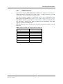
Table 8. RS232 transmission length related to baud rate
Max. Baud Rate [bits/s]
MEN Mikro Elektronik GmbH
20F216-00 E5 – 2014-01-14
Max. Cable Length
2,400
900 m
4,800
300 m
9,600
152 m
19,200
15 m
57,600
5m
115,200
2m
230,400
<1m
21
Functional Description
2.2.3
RS422/485 Interface
RS422 and RS485 are standard interfaces approved by the Electronic Industries
Association (EIA) for connecting serial devices. The RS422 standard was designed
to replace the older RS232 standard because it supports higher data rates and greater
immunity to electrical interference. RS485 is similar to RS422 but can support more
nodes per line because it uses lower-impedance drivers and receivers.
The RS422 interface allows data transmission rates up to 1.152 Mbaud over 60 m.
(The F216 supports a maximum of 921.6 kbaud.) This reduces to 120 kbaud up to
1200 m. The RS422 interface is not only appropriate for point-to-point connections.
"Party line" applications can also be implemented. In this case the line driver is
designed in such a way that it can drive up to 10 line receivers at the same time.
Real "multipoint operation", however, is not permitted by the RS422 interface. This
requires one single bus with several receivers and transmitters to be connected. For
this purpose, the RS485 specification was created, which permits real multipoint
operation with 32 transmitters and 32 receivers on one single bus, while including
all specifications of the RS422 interface.
In theory, both RS422 and RS485 may be configured as 2- or 4-wire interfaces.
However, for the most typical uses, F216 supports only full-duplex operation for
RS422, and half-duplex operation for RS485. The difference between the two
interface types is the number of nodes on one bus (multipoint operation, see above).
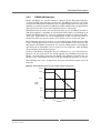
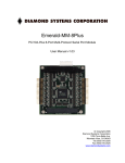
The following table gives an impression of typical transmission lengths related to
baud rates.
Figure 2. RS422/RS485 transmission length related to baud rate
10000 ft
4000 ft
1200 m
1000 ft
Cable
Length
100 ft
40 ft
12 m
10 ft
10
kbps
100
kbps
1
Mbps
10
Mbps
Baud Rate
MEN Mikro Elektronik GmbH
20F216-00 E5 – 2014-01-14
22
Functional Description
2.2.4
Setting the Physical Layer
The eight UART channels can be configured individually as differential RS422 or
RS485, or non-differential (single-ended) RS232 interfaces. The setting is made
using driver software. For Windows MEN offers a driver installation package that
allows easy configuration through the Device Manager. For Linux, VxWorks and
QNX MEN also offers driver software that provides the necessary functions to write
application software.
!
Please note that under Linux, VxWorks and QNX you should always load the driver
with the desired parameter value for the respective physical layer. Otherwise the
driver may change the F216's hardware start-up default stored in the non-volatile
state saver!
The following chapters give hints on how to make settings under the supported
operating systems.
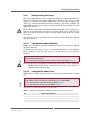
2.2.4.1
Configuration under Windows
MEN’s driver installation package for Windows allows easy configuration through
the Device Manager.
To do this, open the Properties page of each F216 UART device via the Windows
Device Manager, select the Port Interface tab and choose the used physical
interface.
You can find more details on the Windows driver installation package in the F216
under Windows User Manual.
You can download the Windows driver and user manual from MEN’s website.
!
Note: Do not change from RS232 to RS422/485 when there is still a connection
with the RS232 remote station. This will result in a blue screen because of
continuous RS422/485 interrupts.
2.2.4.2
Configuration under Linux
MEN provides a Linux driver that allows to configure the interface mode and baud
rate.
You can find more details on MEN’s Linux driver software in Application Note:
Using 16Z025_UART and 16Z125_UART under Linux (21APPN009).
You can download the application note from MEN’s website.
You can download the Linux driver from MEN’s website.
The baud_base parameter must be set to 1843200.
MEN’s Linux driver supports the following values for the mode parameter:
se
single ended (RS232)
df_fdx
differential, full duplex (RS422)
df_hdxe
differential, half duplex, with echo (RS485)
df_hdx
differential, half duplex, no echo (RS485)
MEN Mikro Elektronik GmbH
20F216-00 E5 – 2014-01-14
23
Functional Description
The following examples show how to use the driver with F216.
Set all UART ports to RS232 mode
# modprobe men_lx_chameleon
# modprobe men_lx_frodo baud_base=1843200
mode=se,se,se,se,se,se,se,se,se
Set all UART ports to RS422 full-duplex mode
In order to change the settings, the driver needs to be removed first.
# modprobe men_lx_chameleon usePciIrq=1
# modprobe men_lx_frodo baud_base=1843200
mode=df_fdx,df_fdx,df_fdx,df_fdx,df_fdx,df_fdx,df_fdx,df_fdx,df_fdx
Note: Most Linux kernels only support 4 UARTs by default. If you need more than
4 UARTs, add parameter 8250.nr_uarts=48 to your kernel boot line in the
bootloader or adjust kernel parameter CONFIG_NR_8250_UARTS and
recompile the kernel.
2.2.4.3
Configuration under VxWorks
MEN provides a VxWorks driver that provides comprehensive I/O control support
to configure the interfaces.
You can find more details on MEN’s VxWorks driver software in the driver’s
included HTML documentation.
You can download the VxWorks driver from MEN’s website.
The UART clock frequency must be set to 58982400. You can use driver function
Z25_CreateDevice or Z25_SetBaseBaud to do this.
2.2.4.4
Configuration under QNX
MEN provides a QNX driver that allows configuration of the interfaces through
QNX tool stty.
The stty tool together with MEN’s QNX driver provides a large number of
parameters to configure serial interfaces. MEN’s driver includes options to set the
physical interface itself. You can get details on the driver using QNX command use
devc-serz025.
You can download the QNX driver from MEN’s website.
To get details on the driver use QNX command use devc-serz025.
You can find more information on stty also on the QNX developer community website.
MEN Mikro Elektronik GmbH
20F216-00 E5 – 2014-01-14
24
Functional Description
2.2.4.5
Start-Up Default Setting
The F216 has a start-up default setting for the physical layer of each channel, which
is hardware-coded by means of a non-volatile state saver. The factory default is
RS422. The state saver always stores the configuration that is present at power-off.
This way you do not need to make any additional settings apart from software
configuration in order to change the default interface.
Please note that the driver software for the various operating systems may have
default physical interfaces different to the F216 hard-coded default. You should
make sure that your application software selects the right interface for each channel,
especially under Linux, VxWorks and QNX.
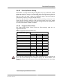
2.2.4.6
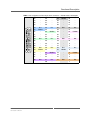
Supported Baud Rates
The F216 provides highly accurate baud rates. The following baud rates are
supported and tested1.
Table 9. Supported and tested baud rates
Desired Baud Rate [bits/s]
!
RS422
RS485
RS232
110
x
x
x
300
x
x
x
1200
x
x
x
2400
x
x
x
4800
x
x
x
9600
x
x
x
19200
x
x
x
38400
x
x
x
57600
x
x
x
115200
x
x
x
230400
x
x
x
460800
x
x
921600
x
x
Please note that at higher baudrates the system performance has to be sufficient to
process the receive interrupts fast enough to prevent the internal FIFOs from
overrunning. It may also be reasonable to reduce the FIFO trigger levels of the F216
UARTs.
1
Other settings are possible but are not tested.
MEN Mikro Elektronik GmbH
20F216-00 E5 – 2014-01-14
Supported with
25
Functional Description
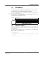
2.3
Front-Panel LEDs
The F216 has four status LEDs at the front panel. Three of them are controlled
through the onboard FPGA (MEN standard 16Z034_GPIO controller). These lines
are user LEDs driven by GPIO lines 0, 1 and 2. Programming these signals as
outputs and driving them to logic 0 means the LED is turned on.
You can control the GPIO lines for the three user LEDs using MDIS4 driver
software available on MEN’s website.
The green FPGA configured LED lights up as soon as the FPGA is loaded, i.e. when
the UART interfaces are ready for operation.
Table 10. Front-panel LEDs
LED No. / Color
1 2 3 4
2.4
Function
1 - red
User LED, controlled through GPIO0
2 - yellow
User LED, controlled through GPIO1
3 - yellow
User LED, controlled through GPIO2
4 - green
FPGA configured, lights up when the FPGA is
loaded, not GPIO-controlled
CompactPCI Interface
The F216 supports a 32-bit 33-MHz CompactPCI interface fully compatible with
CompactPCI specification PICMG 2.0 Rev. 3.0. The board works with 3.3V and
tolerates 5V V I/O.
For full CompactPCI functionality only the J1 connector is needed, therefore the
board only has a J1 connector to the bus.
Connector type of J1:
• 110-pin shielded, 2mm-pitch, 5-row receptacle according to IEC 917 and IEC
1076-4-101
The pin assignment of connector J1 as defined in the CompactPCI specification will
not be repeated here.
MEN Mikro Elektronik GmbH
20F216-00 E5 – 2014-01-14
26
Appendix
3
Appendix
3.1
PCI Configuration
The F216 has the following IDs on the PCI bus:
•
•
•
•
PCI Device ID: 0x4D45
PCI Vendor ID: 0x1A88
Subsystem Device ID: 0x5A14
Subsystem Vendor ID: 0x0072
3.2
Literature and Web Resources
• F216 data sheet with up-to-date information and documentation:
www.men.de/products/02F216-.html
3.2.1
CompactPCI
• CompactPCI Specification Revision 2.0 R3.0:
1997; PCI Industrial Computers Manufacturers Group (PICMG)
www.picmg.org
• PCI Local Bus Specification Revision 2.2:
1995; PCI Special Interest Group
P.O. Box 14070
Portland, OR 97214, USA
www.pcisig.com
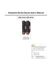
3.3
Finding out the Board’s Article Number, Revision and
Serial Number
MEN user documentation may describe several different models and/or hardware
revisions of the F216. You can find information on the article number, the board
revision and the serial number on two labels attached to the board.
• Article number: Gives the board’s family and model. This is also MEN’s ordering number. To be complete it must have 9 characters.
• Revision number: Gives the hardware revision of the board.
• Serial number: Unique identification assigned during production.
If you need support, you should communicate these numbers to MEN.
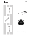
Figure 3. Labels giving the board’s article number, revision and serial number
Complete article number
02F216-00
00.00.00
Revision number
Serial number
MEN Mikro Elektronik GmbH
20F216-00 E5 – 2014-01-14
27