1
Edition: C20140721A
Installation
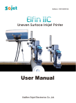
User Manual
*This installation manual is for models: double-printheads inkjet printer,
multi-printheads inkjet printer, ueven surface printer
and egg printing inkjet printer.
XiaMen Sojet Electronics Co.,Ltd.
IMPORTANT
To ensure the best printing quality, we recommend using only our specified cartridges and
the corresponding accessories. Any malfunction or poor printing quality caused by improper
use of other kinds of inks or accessories will be not be guarranteed.
Safety Precautions
There is high voltage inside the machine when it is live. Maintenance or disassembly by
unqualified or unauthorized person is strictly prohibited, so as not to cause any accident.
Machine must be reliably grounded by connecting the grounding wire for the machine during
equipment setup. Unreliable grounding will result in machine failure that the machine cannot
work normally.
Do not expose ink to direct sunlight or high temperature (35℃ above). The heat of direct sunlight or high temperature will affect ink’s storage life and print quality.
If you get ink spill on the eyes or skin during use, please clean your eyes or skin by clean
water.
Ink leakage inside printer can result in burnout damage to the machine. Switch off the
machine and unplug it from power outlet when there’s ink leakage inside printer. Contact
qualified service technician for test and repair.
Warning Signs
Caution: The sign “
” indicates information for caution of possible damage to hardware
of inkjet printer or data loss.
Attention: The sign “
” indicates important notes helpful for your trouble-free operation
of the machine.
02
Content
04
Introduction
05
Important Precautions for Using
06
Chapter 1: Double-printheads Inkjet Printer Installation Manual
07
1.1 Printheads Adjustment
07
1.2 Single Printhead Installation
08
1.3 Double Printheads Installation
09
1.4:Anti-Shock Mechanism & Plate (Optional)
10
1.5 Bracket Installati on
11
Chapter 2: Multi-printheads Inkjet Printer Installatin Manual
12
2.1 Aviation Connector Adjustment
12
2.2 Single Printhead Installation
13
2.3 Combined Printheads Installation
14
2.4 Combined Printheads Installation on Production Line (Optional)
16
Chapter 3: Uneven Surface Printing Inkjet Printer Installastion Manual
17
3.1 Printhead Introduction
17
3.2 Printheads Adjustment
18
3.3 Pole Holder Adjustment for side/down printing
18
3.4 Set up printer, deflector, and anti-shock mechanism
19
3.5 Bracket Installati on
03
Content
20
Chapter4: Egg Printing Inkjet Printer Installation Manual
21
4.1 Printhead Introduction
21
4.2 Printhead Adjustment Module Installation
22
4.3 Bracket Installation
23
Chapter 5: Main Unit Introduction
24
5.1 Double printheads Printer
25
5.2 Controller introduction of the multi-printheads printer
26
5.3 Technical Specifications
04
Important Precautions for Using
Welcome to use this Printer. In order to protect your personal safety and user rights, ensure correct
installation and operation, and full play of the machine, it is important that you read the precautions
carefully.
Important Setup Precautions
*Use exclusive power supply for the equipment. Do not share same power supply with other equipment. Besides, Installation of an additional UPS is recommended.
* Mount the support in sound and stable place. Do not choose the location that will be easily affected
by shock or sway.
* Choose well-working conveyor belt for high print quality.
* Add deflector to the printer for production line setup in order to prevent any printing object hitting
the nozzle plate to cause damage.
* Make sure the printer is well grounded.
* Maintain the distance between deflector and printing object at 0.5-2.5mm as recommended.
* Make sure to insert and remove the ink cartridge by an angle of 15 degree so as not to cause
damage to the cartridge.
* Make sure the setup environment is tidy and clean. Clean the dust on printer from time to time
when dusty environment is unavoidable.
Please read this user manual carefully before first use of the printer for full understanding and attention of important information so that you will get maximum use from your new equipment. This will
also help you have a quick reference to related sections when you have any problems during use.
Note 1: If you cannot solve the problem encountered during use, please contact us for assistance.
Note 2: The information contained herein is subject to change without notice. The amended information will be updated in user manual by new edition.
Note 3: Any machine failure or damage caused by user’s negligence in following this manual will not
be covered by the warranty.
05
Chapter 1:
Double-printheads Inkjet Printer Installation Manual
06
1.1 Printheads Adjustment
Aviation connector default status
Note: for easy operation, installation direction can be
adjusted.
Remove the 3 screws on the connector, take off
the plate, place it into another direction as shown
on the picture, then fasten the screws back.
Connector Adjustment Finish
1.2 Single Printhead Installation
Single Printhead for Side Printing
Single Printhead for Down Printing.
07
1.3 Double Printheads Installation
Fix the two printheads together by 2pcs M3*10
screws;(The diameter of the screwdriver needs to
be less than 3.5mm.)
Fasten the anti-shock plate on the printheads by
3pcs M3*10 screws.
Double printheads installation finish.
Note: While install anti-shock plate, its direction can
be adjusted according to production line direction.
08
1.4:Anti-Shock Mechanism & Plate (Optional)
Note: The anti-shock mechanism and plate is optional, according to demand.
Part List
M4*8 screws
(fix printhead)
M4*8 screws
(fix printhead)
Anti-Shock
Mechanism
Anti-Shock Plate
M3*10 screws
(fix anti-shock plate)
Anti-Shock
Mechanism
Combined Printheads
Anti-Shock Plate
M3*10 screws
(fix anti-shock plate)
Single Printhead
Installation
Combined printheads side printing
Note: The installation direction can be adjusted.
Combined printheads downward printing
Note: The installation direction can be adjusted.
Note: Installation for single printhead is the same as combined printheads.
09
1.5 Bracket Installation
Installation details, please refer to the installation video in the USB disk.
Down Printing of Single Printhead
Side Printing of Single Printhead
Side Printing of Double Printheads
Down Printing of Double Printheads
Separate Printheads Installation
10
Chapter 2
Multi-printheads Inkjet Printer Installatin Manual
*If the printheads need to be separated, please refer to the installation instruction
for double-printheads inkjet printer
11
2.1 Aviation Connector Adjustment
Aviation connector default status
Remove the 3 screws on the connector, take off
Note: for easy operation, installation
the plate, place it into another direction as shown
direction can be adjusted.
in the picture, then fasten the screws back.
Connector Adjustment Finish
2.2 Single Printhead Installation
Single Printhead for Side Printing
Single Printhead for Down Printing
12
2.3 Combined Printheads Installation
Fix the two printheads together by 2pcs
M3*10
screws;(The diameter of the screwdriver
needs to
be less than 3.5mm.)
Use the same way to combine with other
printhead(s).
Anti-Shock Plate
Combined Printheads
We will equip the different anti-shock
plate according to the printheads number
user ordered.
13
2.4 Combined Printheads Installation on Production Line (Optional)
The installation brackets are optional parts, user can order the different installation bracket
according to different installation ways.
Installation for Down Printing
1. After combined the printheads and assemble the anti-shock plate, fix the adjustment modules onto the both sides
of the printheads (as in below picture):
Adjustment Module
Note: The adjustment module enable to adjust the printheads' position vertically, scope is 0-25mm.
2. After the adjustment modules installed, fix the printheads onto the production line:
PH3
PH2
PH1
PH4
PH5
PH6
Fixed Block
Note: 1) Use the gradienter to adjust the position, to make them in the same level.
2) User need to prepare two bars length according to the production line's width, bar diameter need to be 16mm.
3) User may prepare themself or order customized fixed block according to the object's height.
14
Installation for Side Printing
1. After combined the printheads and assemble the anti-shock plate, fix the adjustment modules onto the both
sides of the printheads (as in below picture):
Note: The adjustment module enable to adjust the printheads' position vertically, scope is 0-25mm.
2. After the adjustment modules installed, fix the printheads onto the production line:
PH1
PH2
PH3
PH4
PH5
PH6
Note: Use the gradienter to adjust the position, to make them in the same level.
15
Chapter 3
Uneven Surface Printing Inkjet Printer Installastion Manual
*Suitable for double printheads and multi-printheads uneven surface printing inkjet printers.
16
3.1 Printhead Introduction
Anti-Shock Mechanism
Deflector
Earth wire screws
3.2 Printheads Adjustment
Aviation connector default status
Note: for easy operation, installation direction can be
adjusted.
Remove the 3 screws on the connector, take off
the plate, place it into another direction as shown
on the picture, then fasten the screws back.
Connector Adjustment Finish
17
3.3 Pole Holder Adjustment for side/down printing
Side Printing
Down Printing
3.4 Set up printer, deflector, and anti-shock mechanism
Note: In normal printing,
throw distance is 12.7mm, while
need to print on small curve
surface, we can change to a
9mm deflector.
2
1
Step 2: Replace with
9mm reflector and tighten
the screws.
Step 1: Unfasten the 4 pieces
M3 screws and take the standard
deflector off.
18
3.5 Bracket Installation
Installation details, please refer to the installation video in the USB disk.
Down Printing of Single Printhead
Side Printing of Single Printhead
Separate Printheads Installation
19
Chapter4
Egg Printing Inkjet Printer Installation Manual
20
4.1 Printhead Introduction
Anti-shock Mechanism
Deflector
Earth wire screw
4.2 Printhead Adjustment Module Installation
Fix the adjustment module onto the anti-shock mechanism (as below):
Note: The adjustment module enable to adjust the printheads' position vertically, scope is 0-25mm.
21
4.3 Bracket Installation
1. After assemble the bracket as in above picture, fix it onto the production line.
PH6
PH5
PH4
PH3
PH2
PH1
2. Install the adjustment modules to the printheads firstly, then fix the printheads onto the bracket
by sequence, then the controller (as in above picture);
According to the PH number connect the printhead and the controller.
Note: 1) User can adjust teh printheads' position slightly by the adjustment module according to
the eggs' size.
22
Chapter 5 Main Unit Introduction
23
5.1 Double printheads Printer
USB Port
Power
DB15 port
On-Off Switch
Port of
Port of
Printhead 1 Printhead 2
Ethernet port
Note:1) DB15 port:can connect with external photocell, encoder, alarm kit or external data
source.
2) Ethernet port: can connect with Ethernet cable or external data source.
3) USB port: can connect with USB or external data source.
24
5.2 Controller introduction of the multi-printheads printer
Power button
USB port
Controller top
Power Input
Printhead 1 port
Ethernet port
Printhead 2 port
DB15 port
Printhead 3 port
Printhead 5 port
Printhead 4 port
Printhead 6 port
Controller bottom
Note: 1) DB15 port: can connect to external photocell, encoder, alarm kit or other external data
source.
2) Ethernet port: can connect with ethernet cable or other data source.
3) USB port: can connect to USB disk or other data source.
25
5.3 Technical Specifications
A. Performance Values
Item
Technical source
Specifications
HP TIJ 2.5 Thermal Ink Jet technology
Dimension
Controller(H*W*D): 210*135*37mm/8.3*5.3*1.46inch
Normal printhead:126*100*31mm/4.9*3.9*1.2inch
Stretchable printhead:142*133*55mm/5.6*5.2*2.15inch
Power supply
AC 90V-240V/50-60HZ
Print heights
Double printheads printer:1-25.4mm
Multi printheads printer:1~76.2mm
Uneven surface & Egg printer:1-12.7mm
Print speed
0~60m/min(300DPI)
0~30m/min(600DPI)
Resolution
50~600DPI
Print application
Barcode, alphabetic, numeric, image logos,
date/time, expiration date, shift code, counter, lot-box
code
Connection Ports
Interface
Ink management
Mounting
Product Certification
Environment
requirement
Note
1) Ethernet: 100Mb/s, Synchronized control of multiple
devices via PC;
2) USB2.0: Support U-Disk;
3) DB15: For external devices like photocell,
synchronizer or alarm kit connection;
1) 7 inch 800 *480 color LCD touch screen;
2) With touch screen interface operation, easy to use;
3) Printer can work separately without PC software;
1.Automatically recognizes ink types, and identifies
optimum printing parameters for each ink type;
2. Guarantees the using of genuine original HP ink;
3. Automatic measuring system for the usage of ink.
Standard side and downside printing assembly,
customers can fix it flexibly;
CE, FCC.
1. Working environment: -10°C~ +45°C; 10%-85%RH;
2. Storage environment: -25°C~ +55°C; 10%-90%RH.
26