1
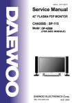
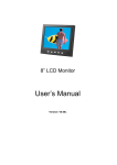
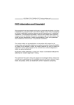
CUPC P100 Series
User Manual
[ P70 / P80/ P90 / P100 / P120 ]
[Version 1.5]
COMFILE Technology Inc.
www.comfiletech.com
CUPC P100 Series User Manual
--------------------------------------------------------------------------------------------------
Table of Contents
Chapter 1. hardware Specification ................................................................................................... 3
Chapter 2. Parts Diagram................................................................................................................. 4
Chapter 3. Dimensions ..................................................................................................................... 6
3-1. CUPC-P70 Dimensions ..................................................................................................... 6
3-2. CUPC-P80 Dimensions ..................................................................................................... 7
3-3. CUPC-P90 Dimensions ..................................................................................................... 8
3-4. CUPC-P100 Dimensions ................................................................................................... 9
3-5. CUPC-P120 Dimensions ................................................................................................. 10
Chapter 4. PANEL CUTOUT .......................................................................................................... 11
4-1. Installation Requirements and Installation ...................................................................... 11
4-2. Bezel Size and Installation .............................................................................................. 12
Chapter 5. Bracket Installation ...................................................................................................... 17
5-1. CUPC-P80 Bracket Installation ...................................................................................... 17
5-2. CUPC-P90 Bracket Installation ...................................................................................... 17
5-3. CUPC-P100 Bracket Installation .................................................................................... 19
5-4. CUPC-P120 Bracket Installation .................................................................................... 20
Chapter 6. Input/Output Connector Type and Pin Assignment ...................................................... 21
6-1. VGA Output Connector.................................................................................................... 21
6-2. RS232C Input/Output Connector (COM1,COM2,COM3) .................................................. 21
6-3. COM4 Mode Setting and Connector ................................................................................ 22
6-4. RS485 Input/Output Connector (COM5) .......................................................................... 23
6-5. Ext. Power ON/OFF Switch Connector ........................................................................... 23
6-6 Power Input Connector .................................................................................................... 24
Chapter 7. System Restoration ...................................................................................................... 25
7-1. Getting Ready .................................................................................................................. 25
7-2. ROM Bios Configuration ................................................................................................... 26
7-2-1. Changing First Boot Device ............................................................................................... 26
7-4. Restoration ...................................................................................................................... 28
7-5. Backing Up ....................................................................................................................... 34
MEMO ............................................................................................................................................. 40
--------------------------------------------------------------------2/40
1175 Chess Dr., Suite F, Foster city, CA 94404, USA
www.comfiletech.com
CUPC P100 Series User Manual
--------------------------------------------------------------------------------------------------
Chapter 1. hardware Specification
MODEL
ITEM
CUPC-P70
CPU
Chipset
BIOS
Display
Chipset
CUPC-P80
Award Bios
AMD LX800 Geode Integrated Graphics Controller
High Performance 2D Accelerator
VGA CRT Output Port
Backlight
White LED
Lifetime :
>20,000hr
White LED
Lifetime : >20,000hr
Ethernet
10/100 Base-T Ethernet Port
VIA VT6107 Ethernet Controller Chip
USB
10.4inch
(1024x768)
300cd/m2
1 Channel CCFL
Lifetime :
>30,000hr
Keyboard
PS/2 Keyboard Port
PS/2 Mouse Port
HDD
Embedded FALSH Disk(4GB), S-ATA Support
Serial
4 RS232C Serial Port.(COM4 RS232 & RS485 S/W Select Port)
One RS485 Serial Port.(Auto Direction Control Support)
DC+12V
Input Power
Weight
Operating
Temperature
2 Channel CCFL
Lifetime : >40,000hr
3 Universal Serial Bus Support
Support USB2.0 Host Controller
1 slot Support
Power
Consumption
15inch (1024x768)
250cd/m2
VT1616 AC97 Codec
Speaker Out Port. MIC In Port
SDCARD
Mouse
CUPC-P120
AMD LX800 & CS5536 Companion Chip
10.2inch (800x480)
350cd/m2
Audio
CUPC-P100
AMD Geode LX800 500MHz Process
Support MMX, AMD 3DNOW Instruction set
7inch (800x480)
300cd/m2
LCD
CUPC-P90
DC+14V
<12W
(1.0A@DC+12V)
<15W
(1.2A@DC+12V)
<17W
(1.2A@DC+14V)
<22W (1.6A@DC+14V)
0.67Kg
1.1Kg
1.8Kg
4.8Kg
00C ~ 600C
4.5Kg
00C ~ 500C
[Table 1] CUPC Hardware Specification
--------------------------------------------------------------------3/40
1175 Chess Dr., Suite F, Foster city, CA 94404, USA
www.comfiletech.com
CUPC P100 Series User Manual
--------------------------------------------------------------------------------------------------
Chapter 2. Parts Diagram
[Figure 1] CUPC Parts Diagram
Name
Description
1
COM1
RS232C Port
2
COM2
RS232C Port
3
COM3
RS232C Port
4
COM4
RS232C/RS485 Port. => Switched to RS232C or RS485 by the mode
selector.1
5
COM5
RS485 port.
6
COM4 Mode Selection
S/W
Switch for selecting COM4 mode. (Refer to Chapter 2-3)
7
USB
Provides 3 USB ports (USB2.0).
2
1
When using RS485 mode, no other RTS signal control is needed because Auto Direction Control
is supported.
2
No other RTS signal control is needed because Auto Direction Control is supported.
--------------------------------------------------------------------4/40
1175 Chess Dr., Suite F, Foster city, CA 94404, USA
www.comfiletech.com
CUPC P100 Series User Manual
--------------------------------------------------------------------------------------------------
3
8
Ethernet
10/100Base-T Ethernet Port (1EA)
9
Audio OUT
Stereo sound output port
10
MIC
Microphone input port.
11
Mouse
PS/2 mouse input port.
12
Keyboard
PS/2 keyboard input port.
13
VGA Out
External monitor video output port
14
ATX Power S/W
ATX mode power switch, which can turn on and off the system.3
15
Power ON/OFF
Power ON/OFF switch.
16
SD Card
17
RESET S/W
Reset switch.
18
Ext. Power S/W
The connector which can be linked to external switch.
Same function with ATX Power S/W.
19
DC INPUT(Adaptor)
Connector for adaptor power supply.
20
DC INPUT
Connector for power supply.
SDCARD slot for OS recovery.
(CAUTION : Use only for OS recovery)
CUPC is released on AT power mode. If you need ATX power mode, please contact us.
--------------------------------------------------------------------5/40
1175 Chess Dr., Suite F, Foster city, CA 94404, USA
www.comfiletech.com
CUPC P100 Series User Manual
--------------------------------------------------------------------------------------------------
Chapter 3. Dimensions
3-1. CUPC-P70 Dimensions
Back cover
of product
Avoid using long bolts
when assembling VESA
mounts or add-on board.
The inner maximum
length is about 9mm.
[Figure 2] CUPC-P70 Dimensions
--------------------------------------------------------------------6/40
1175 Chess Dr., Suite F, Foster city, CA 94404, USA
www.comfiletech.com
CUPC P100 Series User Manual
--------------------------------------------------------------------------------------------------
3-2. CUPC-P80 Dimensions
Back cover
of product
Avoid using long bolts
when assembling
VESA mounts or addon board.
The inner maximum
length is about 9mm.
[Figure 3] CUPC-P80 Dimensions
--------------------------------------------------------------------7/40
1175 Chess Dr., Suite F, Foster city, CA 94404, USA
www.comfiletech.com
CUPC P100 Series User Manual
--------------------------------------------------------------------------------------------------
3-3. CUPC-P90 Dimensions
Back cover
of product
Avoid using long
bolts when assembling
VESA mounts or addon board.
The inner maximum
length is about 9mm.
[Figure 4] CUPC-P90 Dimensions
--------------------------------------------------------------------8/40
1175 Chess Dr., Suite F, Foster city, CA 94404, USA
www.comfiletech.com
CUPC P100 Series User Manual
--------------------------------------------------------------------------------------------------
3-4. CUPC-P100 Dimensions
10
Back cover
of product
Avoid using long
bolts when assembling
VESA mounts or addon board.
The inner maximum
length is about 10mm.
[Figure 5] CUPC-P100 Dimensions
--------------------------------------------------------------------9/40
1175 Chess Dr., Suite F, Foster city, CA 94404, USA
www.comfiletech.com
CUPC P100 Series User Manual
--------------------------------------------------------------------------------------------------
3-5. CUPC-P120 Dimensions
12
Back cover
of product
Avoid using long
bolts when assembling
VESA mounts or addon board.
The inner maximum
length is about 12mm.
[Figure 6] CUPC-P120 Dimensions
--------------------------------------------------------------------10/40
1175 Chess Dr., Suite F, Foster city, CA 94404, USA
www.comfiletech.com
CUPC P100 Series User Manual
--------------------------------------------------------------------------------------------------
Chapter 4. PANEL CUTOUT
4-1. Installation Requirements and Installation
[Installation Requirements]
[Installation]
CUPC
X (Width)
Y (Height)
T (Thickness)
Unit
P70
154
[6.06]
93
[3.66]
1.6 to 5.0
[0.06 to 0.20]
mm
[inch]
P80
265
[10.44]
152
[5.99]
1.6 to 5.0
[0.06 to 0.20]
mm
[inch]
P90
212
[8.34]
159
[6.25]
1.6 to 5.0
[0.06 to 0.20]
mm
[inch]
P100
335
[13.19]
262
[10.32]
1.6 to 15.0
[0.06 to 0.59]
mm
[inch]
P120
335
[13.19]
279
[10.99]
1.6 to 6.0
[0.06 to 0.24]
mm
[inch]
--------------------------------------------------------------------11/40
1175 Chess Dr., Suite F, Foster city, CA 94404, USA
www.comfiletech.com
CUPC P100 Series User Manual
--------------------------------------------------------------------------------------------------
4-2. Bezel Size and Installation
[Figure 7] CUPC-P70 Panel Cutout size
--------------------------------------------------------------------12/40
1175 Chess Dr., Suite F, Foster city, CA 94404, USA
www.comfiletech.com
CUPC P100 Series User Manual
--------------------------------------------------------------------------------------------------
[Figure 8] CUPC-P80 Panel Cutout size
--------------------------------------------------------------------13/40
1175 Chess Dr., Suite F, Foster city, CA 94404, USA
www.comfiletech.com
CUPC P100 Series User Manual
--------------------------------------------------------------------------------------------------
[Figure 9] CUPC-P90 Panel Cutout size
--------------------------------------------------------------------14/40
1175 Chess Dr., Suite F, Foster city, CA 94404, USA
www.comfiletech.com
CUPC P100 Series User Manual
--------------------------------------------------------------------------------------------------
[Figure 10] CUPC-P100 Panel Cutout size
--------------------------------------------------------------------15/40
1175 Chess Dr., Suite F, Foster city, CA 94404, USA
www.comfiletech.com
CUPC P100 Series User Manual
--------------------------------------------------------------------------------------------------
[Figure 11] CUPC-P120 Panel Cutout size
--------------------------------------------------------------------16/40
1175 Chess Dr., Suite F, Foster city, CA 94404, USA
www.comfiletech.com
CUPC P100 Series User Manual
--------------------------------------------------------------------------------------------------
Chapter 5. Bracket Installation
5-1. CUPC-P80 Bracket Installation
1. Insert a bolt into each mounting bracket as shown in the diagram below.
2. Make a hole in the panel according to the CUPC's cutout diagram, and insert the CUPC into
place.
3. Hook a bracket into one of the CUPC's bracket mounting holes, and pull gently to hold it firmly
in place.
4. Tighten the bolt against the panel to secure the CUPC to the panel. (Be careful not to tighten the
bolts too tightly, or the CUPC could be damaged.)
5. Repeat steps 3 and 4 for each mounting bracket.
5-2. CUPC-P90 Bracket Installation
1. Make holes and a rectangle in your panel.
2. Insert the bezel from the front side of your panel.
(The bezel has directions of upside and downside. Refer to the "▲ Upside" mark at the rear side
of bezel)
3. At the rear side of your panel, combine each spacer with 4 bezel bolts and insert them
into CUPC. (The spacers are for protecting the touch screen)
--------------------------------------------------------------------17/40
1175 Chess Dr., Suite F, Foster city, CA 94404, USA
www.comfiletech.com
CUPC P100 Series User Manual
--------------------------------------------------------------------------------------------------
4. Install washers and nuts at the 4 bezel bolts, and tighten the CUPC.
The order is flat washer, spring washer, and then nut. (Do not tighten too tightly, or it may
damage the touch pad.)
Before, Washer and Nut Assy.
(Back Panel)
After, Washer and Nut Assy.
(Back
Panel)
--------------------------------------------------------------------18/40
1175 Chess Dr., Suite F, Foster city, CA 94404, USA
www.comfiletech.com
CUPC P100 Series User Manual
--------------------------------------------------------------------------------------------------
5-3. CUPC-P100 Bracket Installation
When you purchase the product, the bracket for installing P100 to the front panel is
provided.
After mounting the CUPC to the panel, insert the bracket to the side of product and tighten
with the bolts.
--------------------------------------------------------------------19/40
1175 Chess Dr., Suite F, Foster city, CA 94404, USA
www.comfiletech.com
CUPC P100 Series User Manual
--------------------------------------------------------------------------------------------------
5-4. CUPC-P120 Bracket Installation
To fasten CUPC-P120 to an upright panel, the brackets (left 2ea, right 2ea) are supplied when
you purchase P120.
* Procedure *
1) Push and install the CUPC-P120 into your panel.
2) Press the bracket as the following directions in two steps.
3) To fix the CUPC-P120 to the panel, fasten the bolts.
--------------------------------------------------------------------20/40
1175 Chess Dr., Suite F, Foster city, CA 94404, USA
www.comfiletech.com
CUPC P100 Series User Manual
--------------------------------------------------------------------------------------------------
Chapter 6. Input/Output Connector Type and Pin Assignment
6-1. VGA Output Connector
Connector Type
5
4
3
1
2
10
6
15
13
14
12
11
* D-SUB 15 Pin Female
Pin Assignment
Pin No.
Signal
Pin No.
Signal
1
RED
2
GREEN
3
BLUE
4
-
5
GND
6
AGND
7
AGND
8
AGND
9
+5V
10
GND
11
-
12
DDDATA
13
HSYNC
14
VSYNC
15
DDCLK
-
-
[Table 2] VGA Output Connector Type and Pin Assignment
6-2. RS232C Input/Output Connector (COM1,COM2,COM3)
Connector Type
5
4
9
3
8
1
2
7
6
*D-SUB 9Pin Female
Pin Assignment
Pin No.
Signal
Pin No.
Signal
1
DCD
2
RXD
3
TXD
4
DTR
5
GND
6
DSR
7
RTS
8
CTS
9
RI
-
-
[Table 3] RS232C Input/Output Connector Type and Pin Assignment
--------------------------------------------------------------------21/40
1175 Chess Dr., Suite F, Foster city, CA 94404, USA
www.comfiletech.com
CUPC P100 Series User Manual
--------------------------------------------------------------------------------------------------
6-3. COM4 Mode Setting and Connector
6-3-1. RS232C Mode
Mode Setting
Connector Type
RS232C Mode
5
ON
4
9
1
2
3
ON
4
5
7
6
3
8
1
2
6
7
*D-SUB 9 Pin Female
8
OFF
Pin Assignment
Pin No.
Signal
Pin No.
Signal
1
DCD
2
RXD
3
TXD
4
DTR
5
GND
6
DSR
7
RTS
8
CTS
9
RI
-
-
[Table 4] COM4 Connector Type and Pin Assignment for RS232C mode
6-3-2. RS485 Mode
* AutoDirection Control is supported so no other RTS Signal Control required.
Mode Setting
Connector Type
5
4
9
3
8
1
2
7
6
*D-SUB 9 Pin Female
Pin Assignment
Pin No.
Signal
Pin No.
Signal
1
-
2
RS485 DATA+
3
RS485 DATA-
4
-
5
GND
6
-
7
-
8
-
9
-
-
-
[Table 5] COM4 Connector Type and Pin Assignment for RS485 mode
--------------------------------------------------------------------22/40
1175 Chess Dr., Suite F, Foster city, CA 94404, USA
www.comfiletech.com
CUPC P100 Series User Manual
--------------------------------------------------------------------------------------------------
6-4. RS485 Input/Output Connector (COM5)
* AutoDirection Control is supported so no other RTS Signal Control required.
Connector Type
TOP
RS485 D+
RS485 D-
1
GND
2
3
Pin Assignment
Pin No.
Signal
1
RS485 DATA+
2
RS485 DATA-
3
GND
[Table 6] COM5 Connector Type and Pin Assignment
6-5. Ext. Power ON/OFF Switch Connector
* CUPC is released on AT power mode. If you want ATX, please contact us.
Connector Type
2
1
* Part No. : YMW025-02R
Mating Connector : YMH025-02R
Pin Assignment
Pin No.
Signal
1
PWRBTN#
2
GND
[Table 7] Ext. Power ON/OFF Switch Type and Pin Assignment
--------------------------------------------------------------------23/40
1175 Chess Dr., Suite F, Foster city, CA 94404, USA
www.comfiletech.com
CUPC P100 Series User Manual
--------------------------------------------------------------------------------------------------
6-6 Power Input Connector
Connector Type
2
GND
GND
1
DC IN
+12V
DC
Pin Assignment
Pin No.
Signal
1
DC IN
2
GND
[Table 8] Power Input Connector Type and Pin Assignment
!
CAUTION
- Make sure the power supply is turned off when you begin wiring.
- Before you turn on the power supply, please check the voltage of
power supply and wiring is all ok.
--------------------------------------------------------------------24/40
1175 Chess Dr., Suite F, Foster city, CA 94404, USA
www.comfiletech.com
CUPC P100 Series User Manual
--------------------------------------------------------------------------------------------------
Chapter 7. System Restoration
CUPC provides a system restoration solution using Clonix’s WinClon, which is included when you
purchase the OS Option Package. You can restore the CUPC to its original state or to any state you
may have saved using the backup procedure.
7-1. Getting Ready
In order to perform the restoration procedure, the following is needed.
- CUPC
- WinClon Recovery SDCARD
- Keyboard & Mouse (* PS/2 Type is recommended.)
- DC Power
CUPC
DC
Power
Recovery
SDCARD
PS/2
Keyboard
PS/2
Mouse
[Figure 12] Getting Ready
Please be sure to use the recovery SDCARD with the WinClon logo.
[Figure 13] Recovery SDCARD
--------------------------------------------------------------------25/40
1175 Chess Dr., Suite F, Foster city, CA 94404, USA
www.comfiletech.com
CUPC P100 Series User Manual
--------------------------------------------------------------------------------------------------
7-2. ROM Bios Configuration
7-2-1. Changing First Boot Device
After turning on the power, if you press the [DEL] key on the initial screen, the BIOS Setup
Utility will open as shown in Figure 12.
[Figure 14] BIOS SETUP Initial Screen
Select the [Advanced BIOS Features] menu.
[Figure 15] Advanced BIOS Features menu
--------------------------------------------------------------------26/40
1175 Chess Dr., Suite F, Foster city, CA 94404, USA
www.comfiletech.com
CUPC P100 Series User Manual
--------------------------------------------------------------------------------------------------
Choose [USB-HDD] as the First Boot Device.
[Figure 16] BIOS SETUP Save & Exit Screen
Select the Save & Exit Setup option from the menu and confirm your selection by Pressing the Y
Key. The system will then reboot.
7-3. Booting with the WinClon SDCARD
Insert the WinClon Recovery SDCARD and turn on the power.
The System will begin booting into Windows PE as shown in [Figure15].
[Figure 17] WinPE Booting Screen
--------------------------------------------------------------------27/40
1175 Chess Dr., Suite F, Foster city, CA 94404, USA
www.comfiletech.com
CUPC P100 Series User Manual
--------------------------------------------------------------------------------------------------
After the system boots into Windows PE, WinClon will be executed as shown in [Figure 16]
[Figure 18] WinClon Initial Screen
7-4. Restoration
On the initial WinClon screen, click ‘Restore’.
Click
[Figure 19] Restoring Menu Selection
Select the restoration image according to the following steps.
--------------------------------------------------------------------28/40
1175 Chess Dr., Suite F, Foster city, CA 94404, USA
www.comfiletech.com
CUPC P100 Series User Manual
--------------------------------------------------------------------------------------------------
Click
[Figure 20] Selecting Image
Click on the folder icon.
[Figure 21] Exploring image file
--------------------------------------------------------------------29/40
1175 Chess Dr., Suite F, Foster city, CA 94404, USA
www.comfiletech.com
CUPC P100 Series User Manual
--------------------------------------------------------------------------------------------------
[Figure 22] Select image file
In the SD card you purchased, you will find an initial restoration image named by CUPC model.
If you have performed a backup, you may see your own image, too.
Select an image from the list.
Select the partition you want to restore.
In this example, we will restore the entire disk.
--------------------------------------------------------------------30/40
1175 Chess Dr., Suite F, Foster city, CA 94404, USA
www.comfiletech.com
CUPC P100 Series User Manual
--------------------------------------------------------------------------------------------------
Check
[Figure 23] Selecting the restoring partition
Click the ‘Next’ button and select the disk to restore, i.e. Disk1.
Check
[Figure 24] Selecting the restoring disk
Click ‘Next’.
--------------------------------------------------------------------31/40
1175 Chess Dr., Suite F, Foster city, CA 94404, USA
www.comfiletech.com
CUPC P100 Series User Manual
--------------------------------------------------------------------------------------------------
[Figure 25] Restoring Summary Screen
Click ‘Process’.
[Figure 26] Continue Screen
Click ‘Yes’ to confirm.
--------------------------------------------------------------------32/40
1175 Chess Dr., Suite F, Foster city, CA 94404, USA
www.comfiletech.com
CUPC P100 Series User Manual
--------------------------------------------------------------------------------------------------
[Figure 27] Restoration Progress Screen
The restoration process will begin. It will take about 4~5 minutes.
[Figure 28] Restoration Complete
After the restoration is complete, refer to the chapter 7-2-1 to change the CUPC First Boot Device
to HDD-0 and reboot.
--------------------------------------------------------------------33/40
1175 Chess Dr., Suite F, Foster city, CA 94404, USA
www.comfiletech.com
CUPC P100 Series User Manual
--------------------------------------------------------------------------------------------------
7-5. Backing Up
You can also use the WinClon utility to backup the system after customizing it to the state you
want. This will allow you to restore to your custom state rather than the original state.
On the initial WinClon screen, click ‘Backup’.
Click
[Figure 29] Selecting Backup Menu
Select the disk or partition to back up. In this example we will backup the entire disk.
Click
[Figure 30] Selecting the partition and disk to back up
--------------------------------------------------------------------34/40
1175 Chess Dr., Suite F, Foster city, CA 94404, USA
www.comfiletech.com
CUPC P100 Series User Manual
--------------------------------------------------------------------------------------------------
Confirm the selected partition and/or disk.
[Figure 31] Confirm the partition and disk to back up
You are now ready to save the disk to an image file.
Click the folder icon to locate the image file for saving.
Click
[Figure 32] Selecting folder icon
--------------------------------------------------------------------35/40
1175 Chess Dr., Suite F, Foster city, CA 94404, USA
www.comfiletech.com
CUPC P100 Series User Manual
--------------------------------------------------------------------------------------------------
Select the folder and enter a desired file name. Then click the ‘Save’button.
[Figure 33] Input the image file name
Click ‘Next’.
[Figure 34] Image file determined
If you want to protect your image, entered your password and click ‘Next’.
--------------------------------------------------------------------36/40
1175 Chess Dr., Suite F, Foster city, CA 94404, USA
www.comfiletech.com
CUPC P100 Series User Manual
--------------------------------------------------------------------------------------------------
[Figure 35] Password set
Click ‘Process’.
[Figure 36] Backup Summary Screen
--------------------------------------------------------------------37/40
1175 Chess Dr., Suite F, Foster city, CA 94404, USA
www.comfiletech.com
CUPC P100 Series User Manual
--------------------------------------------------------------------------------------------------
Click ‘Yes’ to confirm.
[Figure 37] Backup Start Confirmation Screen
The backup process will begin. It will take about 5~6 minutes.
[Figure 38] Backup Progress Screen
--------------------------------------------------------------------38/40
1175 Chess Dr., Suite F, Foster city, CA 94404, USA
www.comfiletech.com
CUPC P100 Series User Manual
--------------------------------------------------------------------------------------------------
When the backup process is finished WinClon will display the newly created image file.
To fishish,
click ‘OK’.
[Figure 39] Backup Complete
--------------------------------------------------------------------39/40
1175 Chess Dr., Suite F, Foster city, CA 94404, USA
www.comfiletech.com
CUPC P100 Series User Manual
--------------------------------------------------------------------------------------------------
MEMO
--------------------------------------------------------------------40/40
1175 Chess Dr., Suite F, Foster city, CA 94404, USA
www.comfiletech.com