1
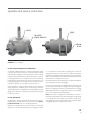
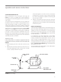
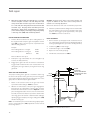
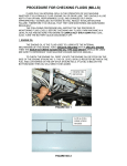
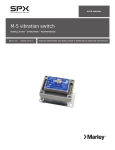
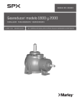
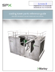
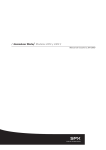
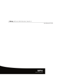
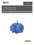
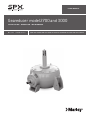
U S E R M A N UA L
Geareducer model 2700 and 3000
®
I N S TA L L AT I O N - O P E R AT I O N - M A I N T E N A N C E
M02-128C
I SSU E D 04/2013
R EAD AN D U N D E R STAN D TH I S MAN UAL PR IOR TO OPE RATI NG OR S E RVICI NG TH I S PROD UCT.
maintenance schedule
Maintenance Service
Monthly
Semi-annually
Seasonal Startup or Annually
x
x
Geareducer Drive:
Inspect and tighten all fasteners including oil plug
Check for and repair oil leaks
x
x
x
Check oil level
x
R
x
Change oil
R
R
Make sure vent is open
x
x
Check driveshaft or coupling alignment
x
Inspect and tighten driveshaft or coupling fasteners
x
Check driveshaft or coupling bushing / flex elements for unusual wear
x
Lube Lines (if equipped)
Check for oil leaks in hoses and fittings
x
R
x
R – Refer to instructions within this manual
Note: It is recommended at least weekly, that the general operation and condition be observed. Pay particular attention to any changes in sound or vibration that may signify a need for closer inspection.
operation and service instructions
VENT
VENT
OIL LEVEL
CHECK AND FILL
DRAIN
PLUG
Figure 1 Service Fittings
Initial Protection Against Corrosion
As shipped, a Marley Geareducer is protected internally against
corrosion with machine enamel on unmachined parts and with
rust-proofing oil and grease on machined surfaces. These coatings
normally protect the Geareducer against atmospheric corrosion
for storage periods up to six months. However, if oil is added to
the Geareducer, it will dissolve the rust-proofing grease and oil,
requiring the Geareducer to be operated once a week to keep a
protective coating of oil on all interior machined surfaces.
Check Geareducer exterior. If exterior finish has been damaged
during shipment or installation, touch up with epoxy paint as required. If Geareducer is equipped with a remote dipstick/oil level
gauge and/or drain line, coat any exposed threads at pipe joints
to prevent corrosion.
Initial Operation
The Geareducer must be filled with oil to the full oil level mark on
the Geareducer case before it is placed in operation. See Changing Geareducer Oil section for oil filling instructions.
Geareducers supplied with new towers include oil for the initial
filling. Oil is not furnished with Geareducers supplied as spares
or on replacement orders. Before operating the mechanical
equipment, check to be sure the oil level is at the full mark at the
Geareducer and that the external gauge placard (if equipped) full
mark corresponds with the “Full” level in the Geareducer. Check
any oil lines to be sure there are no leaks.
Be certain that the vent on the Geareducer (and external dipstick/
oil level gauge, if present) is not plugged.
In order to assure long service life, the Geareducer and motor must
be level, and the drive shaft or coupling must be properly aligned.
Refer to the alignment instructions in the Driveshaft or Coupling
Manual shipped with the cooling tower. Copies are also available
from your local Marley sales representative.
Note—If the tower is equipped with a two-speed motor, allow a
time delay of at least 20 seconds when switching from high speed
to low speed. Allow a time delay of at least two minutes when
changing direction of fan rotation. Failure to provide these delays
may significantly reduce equipment service life.
➠
3
operation and service instructions
Scheduled Maintenance
Lubricants
Warning—Make certain that mechanical equipment is inoperable
during periods of maintenance—or during any situation of possible
endangerment to personnel. If your electrical system contains a
disconnect switch, lock it out until the period of exposure to injury
is over.
To insure maximum performance and service life, it is recommended
Marley factory lubricants be used in all Marley Geareducers.
Marley lubricants can be purchased through your local Marley
sales representative.
Monthly—Check Geareducer oil level. Shut down the unit and
allow 5 minutes for the oil level to stabilize. Add oil if required,
noting the addition in your maintenance log. If equipped with an
external dipstick/oil level gauge, small quantities of oil can be
added at that location.
Semi-annually—If using turbine-type mineral oil, change oil—see
Changing Geareducer Oil for instructions. Check that all the
assembly bolts and cap screws are tight, that oil plugs and pipe
connections are in place and free from leaks, and that the vent on
the Geareducer (and external dipstick/oil level gauge, if present)
is clear—a clogged vent can lead to oil leaks. Intermittent operation and extended periods of downtime can cause condensation
of water in the oil. If using Marley Gearlube, the oil condition must
be inspected every six months—see Changing Geareducer Oil for
maximizing service life.
If lubricants other than Marley factory lubricants are used, they must
not contain any additives (such as detergents or EP additives) which
are adversely affected by moisture and could reduce the service
life of the Geareducer. The responsibility for use of lubricants other
than Marley factory lubricants rests with the customer/owner and
the lubricant supplier.
Seasonal temperature changes may require one viscosity of oil for
summer operation and another for winter operation. Refer to the
tables below for the seasonal selection information.
Annually—Check mechanical equipment anchor bolts, drive shaft
coupling bolts, and coupling set screws. Tighten as required. Check
Geareducer exterior yearly and touch up with epoxy paint if required.
Coat all exposed threads at pipe joints to prevent corrosion.
Every 5 Years—If using Marley synthetic Gearlube, change oil. To
maintain five-year change intervals, use only Marley Gearlube. It
is recommended to monitor the oil condition every six months
throughout the five-year period per the instructions in Changing
Geareducer Oil.
Winter or Summer
Severe Duty/High Temperature
Air Temperature at Geareducer
Below 110°F (43°C)
Above 110°F (43°C)
ISO 150
ISO 220
Table 1 Oil viscosity
4
operation and service instructions
Changing Geareducer Oil
Drain the Geareducer oil by removing the drain plug. See
Figure 1 for location. If equipped with an external dipstick/oil
level gauge, remove the drain plug at that location, and drain the
entire system.
To maximize service life of the Geareducer, remove a sample from
the drained oil and look for evidence of foreign material, such as
water, metal shavings or sludge, or send the oil sample to an oil
analysis lab for inspection. If you find unacceptable condensation
or sludge, flush the Geareducer with mineral oil before refilling.
After inspection is complete, fill the Geareducer with 14 gallons
(53 liters) of oil. See Figure 1 for location. If the Geareducer is
equipped with an external dipstick/oil level gauge an additional 3
to 4 quarts of oil will be required. Be certain that the vent on the
Geareducer (and external dipstick/oil level gauge, if present) is
not plugged. Verify that the gauge/drain line is full and that there
aren't any leaks at the connections.
Alternate procedure:
If the cooling tower has an external oil gauge and drain line
equipped with a three-way valve below the oil level gauge. See
Figure 2.
1.
Remove pipe plug. Turn valve control stem clockwise to open
drain.
2. With Geareducer drained, the three-way valve turned clockwise, and the pipe plug removed, connect fill source (usually
a hose to a pump, to the three-way valve).
OIL GAUGE
VENT
Pump oil through the hose. Check oil level occasionally by
turning the valve control stem counterclockwise and allowing
the oil level in the sight glass to stabilize. Continue filling until
full level mark is reached.
3. With the oil level at the full mark turn the valve control stem
counterclockwise to close the drain and open the valve to the
sight glass. Remove the oil filling line and reinstall pipe plug
in the three-way valve.
Repair and Overhaul
The Model 2700 and 3000 Geareducer is assembled using specialized tools and fixtures. Bearings and gear sets are unique and not
available from other sources. Geareducers can be repaired in the
field—however, major repairs require the use of a fully equipped
machine shop. Refer to the Field Repair section of this manual
for further instructions.
If your Geareducer ever needs replacement or repair, Marley
recommends returning the unit to a Marley factory service center.
Contact your Marley sales representative to discuss course of
action. A factory reconditioned Geareducer carries a one year
warranty. The Marley Order Number on your cooling tower will be
required if the Geareducer is shipped back to the factory for repair.
Obtain a “Customer Return Material” tag from the Marley sales
representative in you area.
To find your Marley sales representative call 913 664 7400 or
check the internet at spxcooling.com.
OIL LEVEL CHECK
OIL LEVEL
GAUGE
DRAIN PLUG
THREE-WAY
VALVE
OIL GAUGE
AND DRAIN LINE
Figure 2 Service Fittings
5
parts list
210
502
BEARING
RETAINER
WATER
SLINGER
203
420
412
VENT
DOWEL PIN
201
CASE COVER
DOWEL PIN
102
202
101
101
PINION
CAGE
PINION
CAGE
CAP
320
008
301
GEAREDUCER
CASE
104
105
103
420
501
312
503
311
204
411
BOTTOM CAP
Figure 3
6
parts list
Parts List
1 Complete Geareducer Assembly
008 Ring Gear Hub
100 Spiral Bevel Gear Set
101
Set of matched spiral bevel gears, including integral pinion shaft with key
Gear ratios as follows:
Model 2700
5.77 to 1
7.71 to 1
8.66 to 1
Model 3000
5.06 to 1
5.44 to 1
6.14 to 1
6.85 to 1
7.91 to 1
8.80 to 1
9.60 to 1
102 Ring gear attaching hardware
103 Lock nut
104 Tongue Washer
105Lockwasher
200 Fan Shaft Set
201
Fan Shaft
202
Ring gear hub key
203
Fan key
204
Ring spacer—Model 2700 Geareducer only
210
Fan attaching hardware
Cap screws and washers
301
310
320
Oil Slinger
Set of Two Pinion Shaft Bearings
311
Head, tapered roller bearing
312
Tail, tapered roller bearing
Pinion Cage Shims
410
420
Fan Shaft Bearing Set
411
Lower tapered roller bearing
412
Upper tapered roller bearing
Fan Shaft Shims
500
501
O-Ring Set
502
Water slinger O-ring
503
Pinion cage O-ring
Pinion Shaft Oil Seal
7
field repair
General
Disassembly
Geareducers can be repaired in the field—however, major repairs
require the use of a fully equipped machine shop. When field repair
or replacement of parts is necessary, the following procedure is
recommended for the disassembly and assembly of the unit. If any
O-ring, oil seal or gasket is to be reused, care should be taken
not to damage it during disassembly. Parts which contain O-rings
or seals should not be jerked or twisted past a shoulder or edge.
These parts are marked with an asterisk (*) in the description
below. O-rings, oil seal and gaskets should be carefully inspected
for damage before being reinstalled. Marley recommends that new
O-rings and oil seal be installed during a major overhaul.
Part numbers and references—refer to Figure 3.
1. Drain oil.
2.
Remove outer ring of bolts in pinion cage and remove pinion
subassembly*.
Note—The thickness of the shim pack (320) is important in resetting the gears. The shim pack should either be saved or carefully
measured with a micrometer. If the gears are to be replaced,
record the pinion setting distance that is etched on the pinion
gear. See Figure 4.
3. Remove water slinger*.
4. Remove bearing retainer and shim pack (420) from top of
case.
Note—The thickness of this shim pack is important in
the endplay and backlash setting of the gears. The shim
pack should either be saved or carefully measured with a
micrometer.
MATCHED NUMBER TO BE COMPARED WITH THE SAME
NUMBER ON THE RING GEAR. (EXAMPLE CO-43)
PINION SETTING DISTANCE. (EXAMPLE 4.860)
BACKLASH (NORMAL) AT WHICH THE GEARS WERE
LAPPED. (EXAMPLE .010)
MATCHED NUMBER TO BE COMPARED WITH THE SAME
NUMBER ON THE PINION GEAR. (EXAMPLE C0-43)
THE PINION SETTING DISTANCE IS THE DISTANCE
THE END OF THE PINION SHOULD BE FROM THE
CENTERLINE OF THE RING GEAR SHAFT.
Figure 4 Gear Match Numbers and Setting Data
8
field repair
5. Drive dowel pins down into case.
6.
7.
Remove bolts and case cover and lift fan shaft assembly out
of the case.
Turn case over and remove bottom cap and shim pack (420).
Pinion Cage Subassembly
1. Place oil slinger (301) on pinion shaft.
2. Press head bearing cone (311) on pinion shaft making sure
oil slinger and bearing are against gear.
Note—The thickness of this shim pack is important in setting the
fan shaft bearing endplay and backlash. This pack should be saved
or carefully measured with a micrometer.
3. Press bearing cups (311 and 312) into pinion cage.
8. Remove bearing cups (411 and 412) from the Geareducer
case and cover.
5. Press tail bearing cone (312) on pinion shaft until it mates
with its bearing cup.
4. Lower pinion cage on pinion shaft, until head bearing cone
and cup mate.
6.
Pinion Cage Disassembly
1. Remove pinion cage cap* from pinion cage.
2. Remove O-ring* (503).
3. Remove locknut, lockwasher and tongue washer (103, 105
and 104) then press pinion shaft (101) out of pinion cage.
This will free tail bearing cone (312).
4. Press oil slinger (301) and head bearing cone (311) from
the pinion shaft.
5. Press bearing cups (311 and 312) out of pinion cage.
Fan Shaft Disassembly
1. Remove ring gear (101) from the ring gear hub
(008).
Install locknut, lockwasher and tongue washer (103, 105 and
104). Tighten nuts on bearing cone until 8 to 12 in·lbƒ (9041356 mN·m) of bearing preload is obtained. Bearing preload
is the resistance in the bearings to shaft rotation measured in
in·lbƒ required to rotate the shaft at uniform velocity. Preload
is necessary to insure the stability of the gear engagement.
Bend tab(s) on lockwasher to secure locknut in place.
7. Install O-ring (503) in groove on pinion cage.
8. Press oil seal onto pinion shaft.
9. Tighten pinion cage cap screws to 45 ft·lbƒ (61 N·m).
10. Record the pinion setting distance that is etched on the pinion
gear. See Figure 4.
Installation of Fan Shaft
4. Press the top bearing cone (412) off of the shaft.
1. Press ring gear hub (008), ring spacer (204—Model 2700
only) and the upper and lower bearing cones (411 and 412)
on the fan shaft (201). Install ring gear (101) on ring gear
hub and tighten cap screws to 75 ft·lbƒ (102 N·m) for Model
2700 or 150 ft·lbƒ (203 N·m) for Model 3000.
Assembly
2 Install the bottom cap using old shim pack or make up
equivalent thickness shim pack (420).
2. Press ring gear hub, ring spacer (204—Model 2700 only)
and lower bearing cone (411) off of the fan shaft (201).
3. Remove lower fan shaft key (202).
Before assembling a new pinion gear in the pinion cage, check
match numbers on pinion gear and spiral bevel ring gear to be
certain that they are a matched set. Gears are lapped in matched
sets at the factory and should not be separated. Numbers are
etched on both the pinion and ring gear as illustrated in Figure 4.
All parts that are to be reused should be thoroughly cleaned before
being reinstalled. Replace bearings if necessary.
3. Press lower fan shaft bearing cup (411) in bore.
4. Install fan shaft assembly in case.
5. Press upper fan shaft bearing cup (412) in cover. Apply a
bead of sealant to the cover flange inboard of the bolt holes.
Install cover on case. Install dowel pins in cover and drive
flush with top of cover.
6. Install cap screws and tighten to 45 ft·lbƒ (61 N·m).
7.
Install bearing retainer using old shim pack (420) or equivalent
thickness and tighten cap screws to 45 ft·lbƒ (61 N·m).
➠
9
field repair
8. Measure fan shaft end play with a dial indicator on a surface
normal to the plane of rotation. Lift shaft axially and rotate
slowly until all axial movement stops. Zero the dial indicator. Lower shaft (zero lifting load) and rotate shaft until axial
movement stops. End play will be read directly from the
dial indicator. Adjust the fan shaft bearings to .003-.005"
(.076-.127mm) end play. The end play is adjusted by adding
or removing shims (420) under the bearing retainer.
Installation of Pinion Cage
1. Find the difference between the pinion setting distance of
the old gear and the new pinion gear and adjust the old shim
pack (320) or make a new shim pack to compensate for the
different setting distances.
Example:
Pinion setting distance of old gear
6.505
Pinion setting distance of new gear
6.500
Difference
.005
Example: Removing .003" shims at the bottom bearing cap
requires the addition of .003" shims at the bearing retainer to
maintain correct bearing adjustment.
Recheck the backlash to make sure it is within the proper limits.
3.
After the equivalent backlash setting has been obtained with
the marked teeth in mesh, check the backlash at two other
points on the ring gear (points approximately 120° apart).
See Table 2, Column 3 for tolerances.
Final Assembly
1. Remove bottom cap and apply a bead of sealant to the bottom cap flange inboard of the bolt holes. Reinstall the bottom
bearing cap and tighten the cap screws to 75 ft·lbƒ (102 N·m).
2. Install O-ring (502) in water slinger.
3. Install water slinger on fan shaft (201).
4. Replace air vent and all pipe plugs.
5. Fill with lubricant selected from Table 1.
Remove .005 from shim pack.
2. Install pinion cage subassembly into case and tighten cap
screws to 75 ft·lbƒ (102 N·m).
3. Engage pinion gear tooth with “X” marked on end between
ring gear teeth marked with “Xs”. Care must be taken not to
damage the pinion gear teeth by forcing them into the ring
gear teeth.
Gear Setting Procedure
The proper mounting of the gear set is essential to obtain long
life and smooth operation of the gears. The pinion and ring gears
were positioned approximately in the preceding steps. The correct
gear position is determined by the gear backlash.
COLLAR
SET SCREW
1. Based on the backlash etched on the gear set, find the
equivalent backlash setting in Table 2, Column 2.
2. With the “X” marked tooth on the pinion gear engaged between the two “X” marked teeth on the ring gear, check the
backlash with a dial indicator as shown in Figure 5. Lock the
pinion shaft against rotation. The amount of movement of the
fan shaft, measured at a distance equal to the outside radius
of the ring gear is the backlash. Obtain backlash setting by
adjusting ring gear axially by removing or adding shims (420)
at bottom bearing cap.
Note—To maintain the previous fan shaft bearing endplay adjustment, a corresponding shim (420) adjustment must be made at
the bearing retainer.
Figure 5 Gear Backlash Measurement
10
TOP VIEW
OF INDICATOR
POINT OF MEASUREMENT
OUTSIDE RADIUS OF GEAR
DIAL INDICATOR
field repair
Backlash Etched on Gears
Set the Gears to Backlash
.008
.010
.003 / .008
.009
.0115
.003 / .008
.010
.013
.003 / .008
.011
.014
.004 / .010
.012
.015
.004 / .010
.013
.017
.004 / .010
.014
.0185
.004 / .010
Table 2
11
Geareducer
user manual
S PX C O O L I N G T E C H N O LO G I E S , I N C .
7401 W 129 STREET
OVERLAND PARK, KANSAS 66213 USA
P: 913 664 7400
F: 913 664 7439
[email protected]
In the interest of technological progress, all products are subject to design
and/or material change without notice
ISSUED 04/2013 M02-128C
COPYRIGHT ©2013 SPX Corporation