1
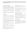
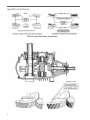
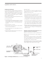
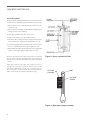
U S E R M A N UA L Geareducer® model 32.2 I N S TA L L AT I O N - O P E R AT I O N - M A I N T E N A N C E M92-1436B I SSU E D 4/2013 R EAD AN D U N D E R STAN D TH I S MAN UAL PR IOR TO OPE RATI NG OR S E RVICI NG TH I S PROD UCT. operation and service PROTECTION AGAINST CORROSION SEASONAL SHUTDOWN (one week to three months) As shipped, a Marley Geareducer is protected against corrosion with machine enamel on unmachined parts and with rust-proofing oil and grease on machined surfaces. These coatings normally protect the Geareducer against atmospheric corrosion for storage periods up to six months. However, if oil is put into the Geareducer, it will dissolve the rust-proofing grease and oil, requiring the Geareducer to be run once a week to keep a protective coating of oil on all interior machined surfaces. See “Seasonal Shutdown” section of this manual for information about non operating period maintenance. 1. At start of shutdown periods, operate Geareducer until oil is warm (120°F), then stop it and change the oil. See section on Lubrication. Check Geareducer exterior yearly. Touch up with paint as required. Exposed pipe threads are coated to prevent corrosion. Touch up coating as required. 2. Each month, drain any water condensation from the lowest point of the Geareducer and its oil system. Check the oil level and add oil if necessary. Operate the Geareducer long enough to recoat all the interior surfaces with oil. 3. To put back into operation, drain water condensation and check oil level. Add oil if necessary. For longer periods of shutdown, see Marley “Cooling Tower Downtime Instructions” Manual 92-1308. INSPECTION OF INTERNAL PARTS INITIAL OPERATION Geareducer vent or vent line must be open to prevent failure of pinion shaft oil seal. In order to check vent line, disconnect it and run a wire through it or blow air through it. Check all gasketed joints for oil seepage. Tighten cap screws and flange bolting if necessary. Check mechanical equipment anchor bolts, drive shaft coupling bolts, and coupling set screws and tighten as required. Geareducers supplied with new towers include oil for the initial filling. Before operating the mechanical equipment, check to be sure the oil is at the full mark at the Geareducer and that the external sight glass placard full mark corresponds with the full level in the Geareducer. Check oil lines to be sure there are no leaks and all joints are tight. After the first week of operation, the original lubricating oil should be replaced. See “Service and Lubrication” section, page 5, for instructions for changing oil. Remove the inspection cover plate from the side of the Geareducer case at each oil change. Check inside of Geareducer for cleanliness of case and internal parts. If any sludge is present, flush inside of Geareducer and connecting oil system. Also at this time, observe the contact pattern of the gear teeth to see if they appear as illustrated in Detail A and B. If incorrect gear tooth pattern should occur, refer to Marley Field Repair Manual for Series 32.2 Geareducer. REPAIR AND OVERHAUL Geareducers can be repaired in the field, however, major repairs require the use of a fully equipped machine shop. If field repair or overhaul is preferred, refer to Geareducer Parts Manual sheets for parts required. Field repair instructions are available from Marley on request. Contact the Marley sales office or Marley representative in your area for information. Lubricating oil is not furnished with Geareducers supplied as spares or on replacement orders. See list of suggested lubricants on page 7 and “Service and Lubrication” section, page 5, for oil filling instructions. After the Geareducer has been filled to the full mark at the Geareducer, make sure there are no oil leaks. Check to be sure the oil full mark at the external sight glass placard corresponds with the full level in the Geareducer. 3 operation and service Detail A—Spiral Bevel Gear Tooth Pattern Detail B—Helical Gear Tooth Pattern 4 operation and service SERVICE AND LUBRICATION Alternate procedure: The horizontal part of the oil gauge and drain line must be level or slightly lower at the sight glass than it is at the Geareducer. The oil capacity of Series 32 Geareducers is 9 gallons. The oil capacity of the optional oil filter is one additional gallon. Connecting oil gauge and drain lines require approximately one gallon of oil. Refer to Table I for suggested lubricants. If the cooling tower has an external oil gauge and drain line equipped with three-way valve below sight glass the following alternate procedure may be used: Fill the Geareducer and gauge and drain line system with oil, using one of the following procedures: Recommended procedure: 1. Pour oil through fill hole in Geareducer inspection cover until it reaches height of “full” mark in the Geareducer case and at the slight glass. See Figures 1 and 3. Reinstall pipe plug in the fill hole. 2. Start fan drive. Run for one minute. 3. Stop the Geareducer. Allow ten minutes for oil level to stabilize and recheck oil level at Geareducer. 4. If necessary, repeat steps 2 and 3 until stabilized oil level is at the proper height. 5. Check placard location. “Full” mark on placard must be at same elevation as “full” mark on Geareducer. 1. Remove pipe plug. Turn valve control stem clockwise to open drain. Collect used oil in an appropriate container. 2. With Geareducer drained, the three-way valve turned clockwise, and the pipe plug removed, connect fill source, either a street ell and stand pipe of sufficient length to extend above top of the sight glass or a hose to a pump, to the three-way valve. Pour oil through a funnel and stand pipe, or pump oil through the hose. Check oil level occasionally by turning the valve control stem counterclockwise and allowing the oil level in the sight glass to stabilize. Continue filling until full level mark is reached. 3. With the oil level at the full mark turn the valve control stem counterclockwise to close the drain and open the valve to the sight glass. Remove the oil filling line and reinstall pipe plug in the three-way valve. Regardless of the procedure used, the Geareducer must be filled to the full mark on the Geareducer. Maintenance of the Geareducer should be scheduled as follows: MONTHLY: Check oil level at least once a week using the following procedure: Stop the Geareducer. Allow ten minutes for oil level to stabilize and check oil level at sight glass. If needed, add oil to Geareducer. If oil is added, repeat steps 2 and 3 of recommended procedure until stabilized oil level is at the proper height. SEMI-ANNUALLY: Change oil at least every 6 month or 3,000 hours of operation. Refer to recommended oil fill procedure. The oil filter cartridge should be replaced at every oil change. Figure 1—Oil Gauge and Drain Line (Series 36 Geareducer is illustrated) 5 operation and service OIL FILTER SERVICE To replace the filter cartridge, first drain the oil from the Geareducer case, then remove the drain plug from the oil filter case. See Fig. 2. 1. Remove the four cap screws attaching the oil filter case cap, and remove cap. 2. Remove and discard oil filter cartridge. Retain cartridge retainer washer and nut for re-installation. 3. Clean gasket material from filter case and cap. 4. Clean inside of filter case, cap and filter hardware. 5. Install new filter cartridge. Reinstall cartridge retainer washer and nut. Install new cap gasket and reinstall filter case cap. 6. Coat drain plug threads with Permatex Pipe Joint Compound No. 51 or equal. Reinstall drain plug and tighten securely. 7. After refilling unit with oil and operating unit, check all gasketed joints for oil seepage. Tighten flange bolts if necessary. Check the oil level placard location each time the oil is changed. The “full” mark on the placard must be at the same elevation as the “full” arrow on the side of the Geareducer case—see Figures 1 and 3. Sight glass vent must be kept open. Inspect at each oil change and clean when necessary. Inspect internal parts and inside of Geareducer case at each oil change—see section on inspection of internal parts. Use oil recommended in Table 1 for the proper atmospheric temperature range. Figure 2—Cross section of oil filter VENT OIL LEVEL PLACARD NOTICE CHECK OIL LEVEL TEN MINUTES AFTER FAN STOPS ROTATING FULL ADD OIL OIL LEVEL GAUGE FILL AT GEAREDUCER REFER TO SERVICE MANUAL FOR OIL CHANGE AND MAINTENANCE RECOMMENDATIONS SPX COOLING TECHNOLOGIES OVERLAND PARK, KS USA 92-110A Figure 3—Sight glass gauge assembly 6 operation and service If lubricants other than Marley factory lubricants are used, they must not contain any additives (such as detergents or EP additives) which are adversely affected by moisture and could reduce the service life of the Geareducer. The responsibility for use of lubricants other than Marley factory lubricants rests with the customer/owner and the lubricant supplier. Seasonal temperature changes may require one viscosity of oil for summer operation and another for winter operation. Refer to the tables below for the seasonal selection information. Winter or Summer Severe Duty/High Temperature Air Temperature at Geareducer Below 110°F (43°C) Above 110°F (43°C) ISO 150 ISO 220 Table 1 Maintenance Service Monthly Semi-annually Seasonal Startup or Annually x x Geareducer Drive: Inspect and tighten all fasteners including oil plug Check for and repair oil leaks x x x Check oil level x R x Change oil R R Make sure vent is open x x Check driveshaft alignment x Inspect and tighten driveshaft fasteners x Check driveshaft bushing / flex elements for unusual wear x Lube Lines (if equipped) Check for oil leaks in hoses and fittings x R x R – Refer to instructions within this manual Note: It is recommended at least weekly, that the general operation and condition be observed. Pay particular attention to any changes in sound or vibration that may signify a need for closer inspection. 7 Geareducer user manual S PX C O O L I N G T E C H N O LO G I E S , I N C . 7401 W 129 STREET OVERLAND PARK, KANSAS 66213 USA P: 913 664 7400 F: 913 664 7439 [email protected] In the interest of technological progress, all products are subject to design and/or material change without notice ISSUED 04/2013 M92-1436B COPYRIGHT ©2013 SPX Corporation