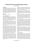
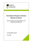
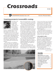
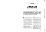
1
400 Commonwealth Drive, Warrendale, PA 15096-0001
SURFACE
VEHICLE
RECOMMENDED
PRACTICE
ISSUED
Prop Dft
APR2002
J2365
Issued
Proposed Draft
2002-04
Calculation of the Time to Complete In-Vehicle Navigation and Route Guidance Tasks
Foreword—A measure of usability and safety of a product is the time required to use that product to complete tasks
of interest (Rubin, 1994). There is considerable data on task completion times for conventional controls and
displays such as the headlights, windshield wipers, the speedometer, the fuel gauge, and audio systems
(Kurokawa, 1990; Green, 1999d). Current evidence is that navigation and route guidance systems have some
functions that can take significantly more time to use than conventional controls and displays (Kurokawa, 1990;
Green, 1999a,c; Tijerina, Parmer, and Goodman, 1998). Furthermore, at various points in the design of a product,
there may be alternative user interfaces under consideration, and ease of use (as measured by task completion
time) should be one of the selection criteria. Therefore, the determination of task completion time is useful.
Task completion times can be determined using a sample of drivers to complete tasks of interest. However, that
process may require a completed design, available only late in development, and obtaining a suitable driver
sample may be cumbersome. As an alternative, the method described in this recommended practice may be used
to calculate static total task times, early in the design.
TABLE OF CONTENTS
1.
Scope ....................................................................................................................................................... 2
2.
2.1
2.2
References ............................................................................................................................................... 2
Applicable Publications ............................................................................................................................ 2
Related Publications ................................................................................................................................. 3
3.
Definitions................................................................................................................................................. 5
4.
Calculation Method................................................................................................................................... 6
Appendix A Operator Times ........................................................................................................................................ 9
Appendix B Calculation Example ............................................................................................................................... 10
Appendix C Tabular Summary of Example Calculation ............................................................................................. 19
SAE Technical Standards Board Rules provide that: “This report is published by SAE to advance the state of technical and engineering sciences. The use of this report is entirely
voluntary, and its applicability and suitability for any particular use, including any patent infringement arising therefrom, is the sole responsibility of the user.”
SAE reviews each technical report at least every five years at which time it may be reaffirmed, revised, or cancelled. SAE invites your written comments and suggestions.
TO PLACE A DOCUMENT ORDER: +1 (724) 776-4970
FAX: +1 (724) 776-0790
SAE WEB ADDRESS http://www.sae.org
Copyright 2001 Society of Automotive Engineers, Inc.
All rights reserved.
Printed in U.S.A.
SAE J2365 Issued Prop Dft APR2002
1.
Scope—This SAE Recommended Practice applies to both Original Equipment Manufacturer (OEM) and
aftermarket route-guidance and navigation system functions for passenger vehicles. This recommended
practice provides a method for calculating the time required to complete navigation system-related tasks.
These estimates may be used as an aid to assess the safety and usability of alternative navigation and route
guidance system interfaces to assist in their design. This document does not consider voice-activated
controls, voice output from the navigation system, communication between the driver and others, or passenger
operation.
2.
References
2.1
Applicable Publications—The following publications form a part of this specification to the extent specified
herein.
2.1.1
ACM PUBLICATION —Available from Association for Computing Machinery, Headquarters Office, One Astor
Plaza, 1515 Broadway, New York, NY 10036-5701, Tel: (+1) 212-869-7440, www.acm.org.
Card, S.K., Moran, T.P., and Newell, A. (1980). The Keystroke-Level Model for User Performance Time
with Interactive Systems, Communications of the ACM, July, 23(7), 396-410.
2.1.2
LA WRENCE ERLBAUM A SSOCIATES AND HUMAN-C OMPUTER INTE RACTION PUBLICA TIONS—Available from
Lawrence Earlbaum Associates, http://erlbaum.com/, 10 Industrial Avenue, Mahway, NJ 07430P2262,
Fax: (+1) 201-236-0072/Toll Free, 1-800-9-BOOKS-9.
Card, S.K., Moran, T.P., and Newell, A. (1983). The Psychology of Human-Computer Interaction,
Hillsdale, NJ: Lawrence Erlbaum Associates.
Olson, J.R. and Nilsen, E. (1987-1988). Analysis of the Cognition Involved in Spreadsheet Software
Interaction, Human-Computer Interaction, 3, 309-349.
2.1.3
INTELLIGENT TRANSPORTATION SOCIETY OF A MERICA P UBLICATION —Available from Intelligent Transportation
Society of America (ITSA), http://www.itsa.org/, 400 Virginia Avenue SW., Suite 800, Washington, DC
20024-2730, Tel: (+1) 202-484-4847 Fax: (+1) 202-484-3483.
Green, P. (1999a). The 15-Second Rule for Driver Information Systems, ITS America Ninth Annual
Meeting Conference Proceedings, Washington, D.C.: Intelligent Transportation Society of America,
(CD-ROM).
2.1.4
H UMAN F ACTORS AND ERGONOMICS S OCIETY—Available from Human Factors and Ergonomics Society, http://
hfes.org, Box 1369, Santa Monica, CA 90496-1369, Tel: (+1) 310-394-1811, Fax: (+1) 310-394-2410.
Green, P. (1999b). Estimating Compliance with the 15-Second Rule for Driver-Interface Usability and
Safety, Proceedings of the Human Factors and Ergonomics Society 43rd Annual Meeting, Santa
Monica, CA: Human Factors and Ergonomics Society (CD-ROM).
2.1.5
U NIVE RSITY OF MICHIGAN TRANSPO RTATIO N R ESEARCH INSTITUTE PUBLICATIO NS—Available
from
the
University of Michigan Transportation Research Institute, www.umtri.umich.edu, 2901 Baxter Road, Ann
Arbor, MI 48109-2105 USA, Tel: (+1) 734-764-2172, Fax: (+1) 734-936-1081.
Green, P. (1999c). Navigation System Data Entry: Estimation of Task Times (Technical Report UMTRI99-17), Ann Arbor, MI, The University of Michigan Transportation Research Institute.
Green, P. (1999d). Visual and Task Demands of Driver Information Systems (Technical Report UMTRI98-16), Ann Arbor, MI: The University of Michigan Transportation Research Institute.
Manes, D., Green, P., and Hunter, D. (1998). Prediction of Destination Entry and Retrieval Times Using
Keystroke-Level Models, (Technical Report UMTRI-96-37, also released as EECS-ITS LAB FT97077), Ann Arbor, MI: The University of Michigan Transportation Research Institute.
-2-
SAE J2365 Issued Prop Dft APR2002
Nowakowski, C. and Green, P. (2000). Prediction of Menu Selection Times Parked and While Driving
Using the SAE J2365 Method (Technical Report 2000-49), Ann Arbor, MI, The University of Michigan
Transportation Research Institute.
Nowakowski, C., Utsui, Y., and Green, P. (2000). Navigation System Evaluation: The Effects of Driver
Workload and Input Devices on Destination Entry Time and Driving Performance and Their
Implications to the SAE Recommended Practice (Technical Report UMTRI-2000-20), Ann Arbor, MI,
The University of Michigan Transportation Research Institute.
2.1.6
N ORTH H OLLAND PUBLICATIO N—Available from North Holland Publishing, c/o Elsevier Science, http://
www.elsevier.nl/, Elsevier Science, Regional Sales Office, Customer Support Department, P.O., Box 945,
New York, NY 10159-0945 USA, Tel: (+1) 212-633-3730, Toll-Free number for North American customers:
1-888-4ES-INFO (437-4636), Fax: (+1) 212-633-3680.
Kieras, D. E. (1997). A Guide to GOMS Model Usability Evaluation Using NGOMSL. In M. Helander, T.
Landauer, and P. Prabhu (Eds.), Handbook of Human-Computer Interaction. (Second Edition).
Amsterdam: North-Holland, 733-766.
2.1.7
VIRGINIA POLY TECHNIC INSTITUTE AND STATE U NIV ERSITY PUBLICATION —Available from UMI, 300 North Zeeb
Road, P.O. Box 1346, Ann Arbor, MI 48106-1346.
Kurokawa, K. (1990). Development of an Evaluation Program for Automotive Instrument Panel Design
(unpublished Ph.D. dissertation), Blacksburg, VA: Virginia Polytechnic Institute and State University.
2.1.8
W ILE Y PUBLICATIO N—Available from Wiley, http://wiley.com/, Corporate Headquarters, 605 Third Avenue,
New York, NY 10158-0012, Tel: (+1) 212-850-6000, Fax: (+1) 212-850-6088.
Rubin, J. (1994). Handbook of Usability Testing, New York, NY: Wiley.
2.1.9
MC GRAW -H ILL P UBLICATIO N—Available from McGraw-Hill, General Customer Service, The McGraw-Hill
Companies, P.O. Box 182604, Columbus, OH 43272, Tel: (+1) 877-833-5524, Fax: (+1) 614-759-3759, http:/
/mcgraw-hill.com.
Schwab, J.L. (1971). Methods Time Measurement (section 5, chapter 2) in Maynard, H.B (ed). Industrial
Engineering Handbook, New York: McGraw-Hill.
2.1.10 VERTIS PUBLICATION —Available from Intelligent Transportation Society of America (ITSA), http://
www.itsa.org/ 400 Virginia Avenue SW., Suite 800, Washington, DC 20024-2730, Tel: (+1) 202-484-4847
Fax: (+1) 202-484-3483.
Tijerina, L., Parmer, E., & Goodman, M.J. (1998). Driver Workload Assessment of Route Guidance
System Destination Entry While Driving: A Test Track Study, Proceedings of the 5th ITS World
Congress, Seoul, Korea: VERTIS, (CD-ROM).
2.2
2.2.1
Related Publications—The following publications are provided for information purposes only and are not a
required part of this document.
ACADE MIC P RES S PUBLICATIO N—Available from Academic Press, 525 B Street, Suite 1900, San Diego, CA
92101-4495, Tel: (+1) 619-231-0926, Customer Ecare: (+1) 888-677-7357, http://academicpress.com.
Cerella, J. (1990). Aging and Information-Processing Rate. In J.E. Birren & W.K. Schaie (Eds.), Handbook
of the Psychology of Aging (3rd Ed), 201-221. San Diego: Academic Press, 201-221.
-3-
SAE J2365 Issued Prop Dft APR2002
2.2.2
US DEPARTMENT O F TRANS PORTATION PUBLICATIO NS—Available from US Department of Transportation,
Federal Highway Administration, Turner-Fairbank Highway Research Center, 6300 Georgetown Pike,
McLean, VA 22101, www.tfhrc.gov.
Hankey, J.M., Dingus, T.A., Hanowski, R.J., Wierwiile, W.W., and Andrews, C. (2000). In-Vehicle
Information Systems Behavioral Model and Design Support: Final Report (Technical Report FHWARD-00-135), McClean, VA: U.S. Department of Transportation, Federal Highway Administration.
Hankey, J.M., Dingus, T.A., Hanowski, R.J., Wierwiile, W.W., and Andrews, C. (2000). In-Vehicle
Information Systems Behavioral Model and Design Support: IVIS Demand Prototype Software User's
Manual (Technical Report FHWA-RD-00-136), McClean, VA: U.S. Department of Transportation,
Federal Highway Administration.
2.2.3
ERTICO PUBLICATION —Available from Intelligent Transportation Society of America (ITSA), http://
www.itsa.org/, 400 Virginia Avenue SW., Suite 800, Washington, DC 20024-2730, Tel: (+1) 202-484-4847
Fax: (+1) 202-484-3483.
Kimura, K., Yamauchi, H., and Kanamori, H. (1999). In-Vehicle Navigation System Operability while
Driving, Proceedings of 6th World Congress on ITS, Toronto, Canada: ERTICO (CD-ROM).
2.2.4
AMERICAN INSTITUTE FOR R ESEA RCH PUBLICATIO N—Available from American Institute for Research, 490
Virginia Road, Floor 1, Concord, MA 01742-2747.
Loring, B.A. and Wiklund, M.E. (1990a). Report on Test of Low-Fidelity Prototypes (technical report),
Bedford, MA: American Institutes for Research.
Loring, B.A. and Wiklund, M.E. (1990b). Report on Baseline Usability Test of Motorola's Prototype 2
(technical report), Bedford, MA: American Institutes for Research.
2.2.5
NHK TECHNICAL R ESE ARCH LABORATORIES PUBLICATIO N—Available from NHK Science & Technical Research
Laboratories, 1-10-11 Kinuta, Setagaya-ku, Tokyo 157-8510, Japan, Tel: (+81) 3-5494-1125, Fax: (+81) 35494-2807, http://www.strl.nhk.or.ip/
Namba, S. (1980). The Amount of Information in a Still-Picture and the Display Time Required (NHK
Laboratories Note Serial # 248), Tokyo, Japan: NHK Technical Research Laboratories.
2.2.6
U NIVE RSITY OF MICHIGAN TRANSPO RTATIO N R ESEARCH INSTITUTE PUBLICATIO N—Available from the University
of Michigan Transportation Research Institute, www.umtri.umich.edu, 2901 Baxter Road, Ann Arbor,
Michigan 48109-2105.
Paelke, G. and Green, P. (1993). Entry of Destinations into Route Guidance Systems: A Human Factors
Evaluation (Technical Report UMTRI-93-45), Ann Arbor, MI: The University of Michigan Transportation
Research Institute.
2.2.7
ELSEVIER S CIENCE PUBLICATIO N—Available from North Holland Publishing, c/o Elsevier Science, http://
www.elsevier.nl/, Elsevier Science, Regional Sales Office, Customer Support Department, P.O. Box 945,
New York, NY 10159-0945 USA, Tel: (+1) 212-633-3730, toll-free number for North American customers: 1888-4ES-INFO (437-4636), Fax: (+1) 212-633-3680.
Wierwille, W.W., Antin, J.F., Dingus, T.A., and Hulse, M.C. (1988). Visual Attentional Demand of an In-Car
Navigation Display System, in Gale, A.G., Freeman, M.H., Haslegrave, C.M., Smith, P., and Taylor,
S.P. (eds.), Vision in Vehicles II, Amsterdam, Elsevier Science, 307-316.
-4-
SAE J2365 Issued Prop Dft APR2002
2.2.8
TAYLO R & F RA NCIS P UBLICATION —Available from Taylor and Francis, http://www.tandf.co.uk/, UK Head
office: 11 New Fetter Lane, London EC4P 4EE, Tel: (+44) 0-7583-9855, Fax: (+44) 0-20-7842-2298.
Wierwille, W.W. (1993). Visual and Manual Demands of In-Car Controls and Displays. In Peacock, B. and
Karwowski, W. eds. Automotive Ergonomics, London, Taylor & Francis, 299-320.
3.
Definitions—For the purposes of this document, the following definitions apply.
3.1
Navigation System—System that identifies the current position of a vehicle on the earth's surface and may
provide guidance to a destination. Information that may be provided includes the road being driven, the
location of cross roads, the heading or compass directions, the distance to a destination, and other items.
3.2
Route Guidance System—System that selects a pathway to a user-specified destination. It also provides
directions to a destination by indicating the route or routes to take using graphics, text, voice, or other means.
Route guidance may be a feature of a navigation system.
3.3
Control—Device used to enter information into a vehicle system.
3.4
Display—Device that presents information to a driver, typically by visual or auditory means though it may be
haptic.
3.5
Driver Interface—General term used to describe the means by which a driver interacts with a vehicle or
vehicle subsystem. The interface typically includes one or more controls and/or displays, as well as the
system’s operating logic.
3.6
Goal— System end state sought by a driver. Examples include: obtaining guidance to a particular destination;
greater magnification of a map display; determining the location of a point of interest; and canceling route
guidance.
3.7
Subgoal— Change in system or device state necessary to achieve a goal. Examples include reach to a
device, entering a street name, entering a street address.
3.8
Task—Sequence of control operations (i.e., a specific method) leading to a goal or subgoal at which the driver
will normally persist until the goal is reached. Example: Obtaining guidance by entering a street address using
the scrolling list method until route guidance is initiated.
3.9
Method—Description of how a goal is accomplished. Example, a location might be entered using (1) the
street address method (entering the city, street, building number, and routing criteria) or (2) the intersection
method (entering the city, the first street name, the second street name, and routing criteria).
3.10 Total Task Time—Time to complete a task.
3.11 Static Total Task Time—Total task time measured in a stationary vehicle, buck, or mock-up in which a
subject is only performing the task of interest.
3.12 Computationally-Interrupted Task—Task where the driver must wait 1.5 seconds or more for the driver
interface to respond to a driver input in order to complete a task, such as when an off-board computer is
queried.
3.13 In Motion—When a vehicle's speed exceeds the minimum nonzero speed that can be reliably detected by the
vehicle's sensors.
3.14 Operator—An elementary perceptual, physical, or cognitive action. Example: a key stroke, a reach, or a
mental operation (see Appendix A for a Table of Operator Times).
-5-
SAE J2365 Issued Prop Dft APR2002
3.15 Shortcut—An alternative method by which a task may be completed more quickly.
EXAMPLE—For the PathMaster navigation interface, when a city is being selected, recently visited cities
appear before the alphabetical list of cities.
3.16 Pseudo code—Description of a computer program that utilizes English (or some other natural language)
phrases (e.g., add a to b, compute the square room of the sum) in a structure similar to that of a programming
language (usually an indented outline). Pseudo code lacks the syntax rules of formal computer languages
such as BASIC or C and is not intended to compile. Pseudo code is often a precursor to formal coding.
4.
Calculation Method
4.1
Overview—The calculation method is based on the goals, operators, methods and selection rules (GOMS)
model described by Card, Moran, and Newell (1980, 1983). For background on the calculation method see
Green (1999b,d).
The basic approach involves top-down, successive decomposition of a task. The analyst divides the task into
logical steps. For each step the analyst identifies the human and device task operators. Sometimes analysts
get stuck using this approach because they are not sure how to divide a task into steps. In those cases,
utilizing a bottom-up approach may overcome such roadblocks.
The GOMS approach assumes error-free performance, well-learned tasks, and particular locations of controls,
assumptions typically violated in the operation of motor vehicles. Modifications have been made to the GOMS
model (e.g., Kieras, 1997) to improve the accuracy of the method and adjust the parameters to more closely
approximate the task times in motor vehicles.
More specifically, the general process is:
4.1.1
OBTAIN E ITHER :
a working prototype of the interface; or
a simulation of the interface; or
a videotape of a user operating the interface; or
a step-by-step operational description.
Also obtain the city and street database used, as well as any other data the system might access (e.g.,
dynamic traffic information). Supporting documentation (e.g., quick reference card, user manual) is also
helpful.
4.1.2
Identify the goals (e.g., enter a street address, enter an intersection).
4.1.3
For each goal, identify the associated other subgoals to achieve it. Goals may be at multiple levels.
4.1.4
For each goal and subgoal, identify the methods (e.g., the list search method) used to achieve them.
Document the methods with a detailed explanation.
4.1.4.1
Advice—The videotape assists in the accurate analysis of the methods used by subjects. Videotapes
provide a useful record of screen actions, example screens and when a user pauses for a mental
operation, pauses that analysts may omit when then just think about what users might do. When
recording, be sure the camera is perpendicular to the test screen and interference due to the user's hand is
minimized. Also make sure the image is closely cropped around the display so the change of single
characters is readily apparent on the recording. Using a second camera viewing from the side and
painting the sides of switches contrasting colors makes the depression of short throw switches easier to
see on the recording.
-6-
SAE J2365 Issued Prop Dft APR2002
4.1.5
Convert the detailed explanation of the methods into a computer-program like format (pseudo code).
4.1.6
Identify the computational assumptions with regard to user’s knowledge of various methods of task
completion (Table 1).
TABLE 1—COMPUTATIONAL ASSUMPTIONS
Analysis Assumption
Comments
Adjustment to Analysis
Error-free performance
The computational method assumes drivers start with
accurate and complete information about the destination
and do not make any mistakes in entering information. In
fact, errors can be quite high, ranging from 10 to 50 % of the
trials.
Rather than attempting to determine the
probability of each error and the time to
correct it, the completion time can be
increased by 25% to account for typical
performance.
Routine cognitive task
The method assumes that drivers know what to do at each
step. However, navigation system use is not a highly
learned task for some drivers and drivers sometimes forget
what to do.
Model estimates are improved by including
additional mental operations where
forgetting is likely to occur (Card, Moran and
Newell, 1983). Adjustments for forgetting
should be based on empirical analysis or
using expert rules.
Automotive context
(The original model was
developed for predicting
task times in an office.)
The position of a mouse varies from movement to
movement but automotive controls do not. However,
automotive controls may require greater reach accuracy. In
addition, vehicle motion may slightly elevate times to reach
for controls.
Utilize automotive-specific estimates of
reach and movement time. Evaluators may
wish to develop their own operator values or
correction factors, as well as additional
application rules to improve estimates.
Warm start
The navigation system is assumed to be on and the
disclaimer screen is cleared.
Start task estimate from the "main menu."
Use only visible, noncognitively loading
shortcuts
Many of the goals can be achieved using more than one
method. Some shortcuts, while visible, are not simple. For
example, if the goal was to scroll to a name starting with the
letter "z" and the initial point was the letter "a," then in some
systems, the optimal method to get there would be to scroll
backwards in the alphabet.
Ignore methods of which only experts would
be aware or are cognitively loading (such as
reciting the alphabet backwards). Data on
the frequency of use of shortcuts is needed.
Include system response Delays in system response occur as systems scroll lists,
time (except for
update maps, and so forth.
computationallyinterrupted tasks)
Since the individual waits for these updates,
system response time should be included in
the task time except for computationally
interrupted tasks.
Perfect knowledge of the Likely problems include (1) incomplete knowledge of the city For ease of computation, assume the
address.
of the destination (is the street address in Ann Arbor or Ann complete address is known.
Arbor Township), (2) missing prefix for streets (1st St vs. S
1st St), and missing street suffix (Allen vs. Allen Road).
Parallel completion of
control operations and
decision making.
For some tasks drivers will operate controls and plan
operations at the same time.
-7-
For operations performed in parallel, use the
longest completion time of control operations
and decision making to estimate total task
completion time.
SAE J2365 Issued Prop Dft APR2002
4.1.7
Determine the appropriate mental, keystroke, and other operators for each step using the data in Appendix
A. Entry into a spreadsheet is recommended.
The most challenging aspect of this step is to decide where to include mental operators. Suggested rules for
where to include them follow.
a.
b.
c.
Include at least one mental operator every time a menu must be read or a major decision needs to be
made.
If a decision can be fully anticipated because all of the information needed is visible well in advance of
the decision point, a mental operator is not included in the sequence. So, when scrolling through a list
entry-by-entry (assuming the entries are shown on a display), the sequence of operators would be
“cursor, cursor, cursor,” not “mental, cursor, mental, cursor, mental, cursor” because the user could
think about what needed to be done next in parallel with pressing a cursor key. However, if the cursor
action clears the screen (e.g., in alphabetic advance), then a mental operator would be included
because the user needs to read the display. The sequence would be “mental, next screen, mental,
next screen,” etc. There are times that this rule needs to be modified, such as when scrolling to the
place in the alphabet where decisions can be anticipated. Some of the mental operators can be
omitted in such cases.
When scrolling through long lists, a mental operator occurs just before pressing the enter key to
confirm the correct item is to be selected. For decisions based on short lists, no mental operator is
needed.
4.1.8
Enter the execution times for each operator (from Appendix A). (A spreadsheet is recommended.)
4.1.9
Add up the execution times for each operator.
4.1.10 Adjust the keystroke times using the age multiplier as desired. For young drivers (18-30), use the keystroke,
mental and search times as is, for middle aged drivers (40-55), multiply the keystroke times by 1.4. For
drivers 55-60 multiply the keystroke times 1.7. For older drivers (>65), multiple the keystroke times by 2.2.
4.1.11 Verify that the times make sense and revise as needed. Carefully review the inclusion of mental operators.
4.1.11.1 Advice—Reviewing videotapes of typical users interacting with the system will help verify methods,
selection rules, operators and times. When played back at slow speed on a frame-accurate VCR, these
tapes can be used to estimate screen update and system calculation times.
PREPARED BY THE SAE SAFETY AND HUMAN FACTORS COMMITTEE
-8-
SAE J2365 Issued Prop Dft APR2002
APPENDIX A
OPERATOR TIMES
A.1
Table A1 shows the operator times that can be used. These values were based on (1) the classical KeystrokeLevel Model operators described by Card, Moran, and Newell (1980, 1983) obtained from a variety of office
tasks, (2) data from from Olson and Nilsen (1997-1998) for spreadsheet use, (3) data from Manes, Green, and
Hunter (1998) for entering data into a Siemens Ali-Scout Navigation System, and (4) reach times from
Methods Time Measurement-1 (MTM-1), the most popular predetermined time system used by industrial
engineers (Schwab, 1971). The age correction factor (in 4.1.10) is based on the work of Manes, Green, and
Hunter (1998). Operator time estimates based on the office data may be too low because navigation data
entry tasks are not well learned (i.e., not routine cognitive tasks) and because automotive interior design does
not facilitate rapid keyboard entry as in an office, even when the vehicle is stationary. The operator times from
office work were adjusted upwards to be consistent with empirical studies of driver behavior. Additional
information on the development of the operator times appears in Green (1999b). Some validation data appear
in Nowakowski and Green (2000) and Nowakowski, Utsui, and Green (2000). Note that times are based on
hard key operation of specific systems and may need to be adjusted for the specific device of interest (e.g.,
adjust operator times for touch screen input).
TABLE A1—OPERATOR TIMES (SECONDS)
Code
Name
Operator Description
Time(s)
Time(s)
Young Drivers Older Drivers
(18-30)
(55-60)
Rn
Reach near
from steering wheel to other parts of the wheel, stalks, or pods
0.31
0.53
Rf
Reach far
from steering wheel to center console
0.45
0.77
C1
Cursor once
press a cursor key once
0.80
1.36
C2
Cursor 2 times or more
time/keystroke for the second and each successive cursor
keystroke
0.40
0.68
L1
Letter or space 1
press a letter or space key once
1.00
1.70
L2
Letter or space 2 times or more
time/keystroke for the second and each successive cursor
keystroke
0.50
0.85
N1
Number once
press the letter or space key once
0.90
1.53
N2
Number 2 times or more
time/keystroke for the second and each successive number key
0.45
0.77
E
Enter
press the enter key
1.20
2.04
F
Function keys or shift
press the function keys or shift
1.20
2.04
M
Mental
time/mental operation
1.50
2.55
S
Search
search for something on the display
2.30
3.91
Rs
Response time of system-scroll
time to scroll one line
0.00
0.00
Rm
Response time of system-new menu
time for new menu to be painted
0.50
0.50
NOTE 1—The keystroke times shown in Table A1 include the time to move between keys.
NOTE 2—System response times to show new menus may be empirically determined.
-9-
SAE J2365 Issued Prop Dft APR2002
APPENDIX B
CALCULATION EXAMPLE
B.1
Following is an example of entering a business address, 2901 Baxter Road, Ann Arbor, Michigan, into a
Rockwell Pathmaster with Magellan Pathmaster software (version 3.31) with the Great Lakes database
(version 30J.0372.01) loaded. Readers should note that the database is fluid, so that some short cuts may be
available depending upon the recent driving history. The example that follows uses the street address method.
It assumes that address has not been recently visited (so it is not on the guidance history list) nor has Ann
Arbor (so the city is not on the city shortcuts list).
B.1.1 Obtain a working model of the navigation device and the software, or a prototype, or a detailed description of
how the device is to be operated. Figure B1 shows the driver interface of the Magellan Pathmaster, the
example case.
FIGURE B1—PATHMASTER USER INTERFACE
B.1.2 Identify the goal (e.g., obtain navigation instructions to a street address, obtain navigation instructions to an
intersection).
B.1.3 For each goal, identify subgoals that must be achieved to complete that goal. Those subgoals may be at
multiple levels.
In this example, the goal is to enter an address using the street address method. Following are subgoals.
B.1.3.1 ASSUMPTIO N—The starting point is the destination method selection screen. After the title screen clears (by
itself) and the driver clears the disclaimer screen, this screen appears.
-10-
SAE J2365 Issued Prop Dft APR2002
B.1.3.2 GO AL —Enter the destination using the street address method.
Subgoal 0: Move a hand to the device.
Subgoal 1: Select destination entry via street address mode.
Subgoal 2: Select a city.
Subgoal 3: Select a street.
Subgoal 4: Select a street address.
Subgoal 5: Select route criteria.
B.1.4 Identify the methods used to achieve each subgoal.
B.1.4.1 SUBGOAL 0—Move a hand to the device.
a.
Method: Reach for the navigation device.
B.1.4.2 SUBGOAL 1—Select destination entry via street address mode.
a.
Method: Find the destination entry item on the initial menu and select it.
B.1.4.3 SUBGOAL 2—Select a city.
a.
Method: Scroll through the list of cities until the desired city is found. If the first letter of the city name
does not match the first letter for the desired name, use the up and down arrow keys until a matching
first letter is found. Then use the right and left arrows to scroll through the list of cities one city at a
time. When a match is found, select it. Shortcut: If the city was recently visited, it appears on the
recent list at the beginning of the city list. Use the up arrow keys to scroll to a possibly matching name.
In all cases, when a match is found, select it.
B.1.4.4 SUBGOAL 3—Select a street.
a.
Method: This procedure is similar to that for selecting a city, except that a street name is being
matched, not a city name.
B.1.4.5 SUBGOAL 4—Select a street address.
a.
Method: Compare the first column of the desired street address with the display address. If the
columns values match, move to the next column (using the right and left arrow keys). If they do not
match, then use the up and down arrow keys to increase or decrease the displayed value to match the
desired address. When all the values match, select the address (by hitting enter).
B.1.4.6 SUBGOAL 5—Select route criteria.
a.
Method: Select the desired criteria from the list of 3 shown.
B.1.5 Convert the word/sentence-based description of the methods into pseudocode (a computer-program like
format). See step 6 for an example.
B.1.6 Identify the calculation assumptions with regard to knowledge of various methods, the extent to which switch
operations and cognitive activities are completed in parallel, etc. Table 1 of Annex 2 shows some of the basic
assumptions.
B.1.6.1 SUBGOAL 0—Move a hand to the device.
a.
Method: Reach for the device.
-11-
SAE J2365 Issued Prop Dft APR2002
B.1.6.2 SUBGOAL 1—Get to the desired destination entry mode.
a.
Method: Find the destination entry item on the initial menu and select it. Read the destination mode
screen (Figure B2) and search for “street address.” Press the enter key to select the first entry
FIGURE B2—DESTINATION MODE SCREEN
B.1.6.2.1 Assumption—The normal process of selecting an item from a list is:
a.
b.
c.
d.
Read the list and find the desired item.
Scroll down to the desired item.
Confirm the desired item is highlighted.
Select the item by pressing the enter key.
However, when the desired item is the first item in the list, steps 2 and 3 are omitted. For long lists, the
process of pressing keys (to scroll) down and reading the list of options appear to occur in parallel, with the
keypress times determining the scrolling completion time. The final confirmation, however, still occurs.
B.1.6.3 SUBGOAL 2—Select a city.
a.
Method: After the city menu has appeared, scroll through the list of cities until the desired city is found.
(See Figure B3.) If the first letter of the city name does not match the first letter for the desired name,
use the right arrow key until a matching first letter is found. Then use the down arrow key to scroll
through the list of cities one city at a time. When a matching city is found, select it.
-12-
SAE J2365 Issued Prop Dft APR2002
FIGURE B3—CITY SCREENS
B.1.6.3.1 Pseudo code—Method for subgoal: find matching entry in alphabetized list using sequential scrolling
method
wait for the beginning of the city listing to appear
1.
2.
read highlighted item and decide if 1st letter of current entry matches desired city
if first pass, then select method (sequential scrolling or scroll by first letter of name)
if not matching 1st letter then scroll by first letter of name
press right side of round switch to go to next letter
go to step 1 (decide if match, note: reading occurred earlier)
if matching 1st letter
current letter = second letter
compare current letter of highlighted item with desired city name
2.1 if current letter matches and last letter (confirm correct entry) Are you done?
press enter
go to exit: next subgoal
if current letter matches and not last letter
increment current letter
go to 2.1 (compare current letter)
if current letter does not match
press bottom of key to scroll down 1 entry (see note 1)
go to 2.1
exit: next subgoal
NOTE 1—As noted previously, when scrolling long lists for in-vehicle systems, observation has shown that
reading text and key presses to scroll the list appear to occur in parallel. The times are for key
presses.
NOTE 2—By observation, only expert users make use of scrolling by first letter of name combined with
backwards scrolling through the alphabetically ordered list to retrieve city and street names, so
the reverse alphabetic scrolling method was not considered.
-13-
SAE J2365 Issued Prop Dft APR2002
B.1.6.4 SUBGOAL 3—Select a street.
This procedure is similar to that for selecting a city, except that a street name is being matched, not a city
name. For convenience, it is repeated here.
B.1.6.4.1 Method—After the list of streets has appeared, scroll through the list of streets until the desired street is
found. If the first letter of the street name does not match the first letter for the desired name, use the right
arrow keys until a match first letter is found. Then use the down arrows to scroll through the list of streets
one street at a time. When a match is found, select it. (See Figure B4.)
B.1.6.4.2 Pseudo code—Method for Subgoal: find matching entry in alphabetized list using sequential scrolling
method
wait for list of streets to appear
1. read highlighted item, decide if 1st character of name of current entry matches desired street (see note
1)
2. if first pass, selected method (sequential scrolling or alpha scrolling by first letter of the name)
if not matching 1st character
press right arrow key to go to next character
go to step 1 (to read the next item)
if matching 1st character
current character = second character
compare current character of highlighted item with desired street
2.1 if current character matches and last character
confirm correct entry
hit enter
go to next subgoal
if current character matches and not last character
increment current character
go to 2.1 (compare current character )
if current character does not match displayed character
press key to scroll down 1 entry (see note 2)
go to 2.1
exit: next subgoal
NOTE 3—In the initial name comparison, N, S, E, and W (e.g., N 1ST ST) are ignored.
NOTE 4—This sequence only approximates that which subjects use as some grouping of the street
designators (st., ave., dr., etc.) is likely. However, that grouping has only a minor impact on the
total task time, so for ease of calculation, grouping can be ignored.
B.1.6.5 SUBGOAL 4—Select a street address.
a.
Method: After the screen showing the range of streets appears, compare the first column of the
desired street address with the display address. If the columns values match, move to the next
column (using the right arrow keys). If they do not match, then use the up and down arrow keys to
increase or decrease the displayed value to match that of the desired address. When all the values
match, select the address (using enter). (See Figure B5.)
-14-
SAE J2365 Issued Prop Dft APR2002
FIGURE B4—LIST OF STREET NAMES
-15-
SAE J2365 Issued Prop Dft APR2002
FIGURE B5—STREET NUMBER SCREENS
-16-
SAE J2365 Issued Prop Dft APR2002
B.1.6.5.1 Psuedo Code—Method for incrementing/decrementing numbers using 4-way cursor switch (round key)
Recall the desired street address, read the maximum allowable street address, and if necessary, include
leading zeros in the recalled address to match the number of characters in the maximum value.
current digit=left most digit
determine next field to change: Decide if the value in the current display field is the same as that in the
recalled field
1.
decide if value of currently displayed field less than, equal to, or greater than the value of recalled field
case 1: currently displayed field = value of recalled field
decide if last field
if last field
confirm displayed = recalled street number
hit enter key
go to exit
if not last field
go to next field: press right side of arrow key, current digit = next digit
go to 1
case 2: displayed > recalled
compute difference in current field = (displayed recalled)
decrease display value by pressing bottom of key “difference” times
confirm displayed = recalled
go to case 1
case 3: displayed < recalled (note 1)
compute difference in current field = (displayed recalled)
increase display value by pressing up arrow key the number of times = “difference”
confirm displayed = recalled
go to case 1
Exit
B.1.6.6 SUBGOAL 5: SELECT RO UTE
a.
CRITERIA .
Method—After the route criteria screen appears, select the desired criteria from the list of 3 shown.
(See Figure B6.)
NOTE 5—At this point, the task timing ends and the person returns to driving. However, several seconds
are required for the system to calculate a route and display the route. That added time is not
included in the total task time.
-17-
SAE J2365 Issued Prop Dft APR2002
FIGURE B6—ROUTE SELECTION CRITERIA
B.1.6.6.1 Psuedo Code—Method for Selecting Route Criteria
Read the “route criteria” screen and search for “shortest time route”
Press the enter key to select the first entry.
NOTE 6—Assumptions are the same as for the address entry method selection described previously.
B.1.7 Determine the appropriate mental, keystroke, and other operators that are appropriate for each step (see
Appendix A).
B.1.8 Enter the times from Appendix A for each operator.
B.1.9 Adjust the keystroke times using the age multiplier as desired. For young drivers (18-30), use the keystroke,
mental and search times as is, for middle aged drivers (40-55), multiply the keystroke times by 1.4. For drivers
55-60 multiply the keystroke times 1.7. For older drivers (>65), multiple the keystroke times by 2.2.
B.1.10 Add up the execution times for each subgoal and goal. A spreadsheet is recommended.
For an example see Appendix C.
B.1.11 Verify that the times are reasonable based on literature, expert analyses, and/or conducting new empirical
studies and revise the analysis as needed
-18-
SAE J2365 Issued Prop Dft APR2002
APPENDIX C
TABULAR SUMMARY OF EXAMPLE CALCULATION
FIGURE C1—TABULAR SUMMARY OF EXAMPLE CALCULATION
-19-
SAE J2365 Issued Prop Dft APR2002
FIGURE C2—TABULAR SUMMARY OF EXAMPLE CALCULATION (CONTINUED)
-20-
SAE J2365 Issued Prop Dft APR2002
FIGURE C3—TABULAR SUMMARY OF EXAMPLE CALCULATION (CONTINUED)
-21-
SAE J2365 Issued Prop Dft APR2002
Rationale—Not applicable.
Relationship of SAE Standard to ISO Standard—Not applicable.
Application—This SAE Recommended Practice applies to both Original Equipment Manufacturer (OEM) and
aftermarket route-guidance and navigation system functions for passenger vehicles. This recommended
practice provides a method for calculating the time required to complete navigation system-related tasks.
These estimates may be used as an aid to assess the safety and usability of alternative navigation and
route guidance system interfaces to assist in their design. This document does not consider voiceactivated controls, voice output from the navigation system, communication between the driver and
others, or passenger operation.
Reference Section
Card, S.K., Moran, T.P., and Newell, A. (1980). The Keystroke-Level Model for User Performance Time
with Interactive Systems, Communications of the ACM, July, 23(7), 396-410.
Card, S.K., Moran, T.P., and Newell, A. (1983). The Psychology of Human-Computer Interaction,
Hillsdale, NJ: Lawrence Erlbaum Associates.
Cerella, J. (1990). Aging and Information-Processing Rate. In J.E. Birren & W.K. Schaie (Eds.),
Handbook of the Psychology of Aging (3rd Ed), 201-221. San Diego: Academic Press, 201221.
Green, P. (1999a). The 15-Second Rule for Driver Information Systems, ITS America Ninth Annual
Meeting Conference Proceedings, Washington, D.C.: Intelligent Transportation Society of
America, (CD-ROM).
Green, P. (1999b). Estimating Compliance with the 15-Second Rule for Driver-Interface Usability and
Safety, Proceedings of the Human Factors and Ergonomics Society 43rd Annual Meeting,
Santa Monica, CA: Human Factors and Ergonomics Society (CD-ROM).
Green, P. (1999c). Navigation System Data Entry: Estimation of Task Times (Technical Report UMTRI99-17), Ann Arbor, MI, The University of Michigan Transportation Research Institute.
Green, P. (1999d). Visual and Task Demands of Driver Information Systems (Technical Report UMTRI98-16), Ann Arbor, MI: The University of Michigan Transportation Research Institute.
Hankey, J.M., Dingus, T.A., Hanowski, R.J., Wierwiile, W.W., and Andrews, C. (2000). In-Vehicle
Information Systems Behavioral Model and Design Support: Final Report (Technical Report
FHWA-RD-00-135), McClean, VA: U.S. Department of Transportation, Federal Highway
Administration.
Hankey, J.M., Dingus, T.A., Hanowski, R.J., Wierwiile, W.W., and Andrews, C. (2000). In-Vehicle
Information Systems Behavioral Model and Design Support: IVIS Demand Prototype
Software User's Manual (Technical Report FHWA-RD-00-136), McClean, VA: U.S.
Department of Transportation, Federal Highway Administration.
Kieras, D. E. (1997). A Guide to GOMS Model Usability Evaluation Using NGOMSL. In M. Helander, T.
Landauer, and P. Prabhu (Eds.), Handbook of Human-Computer Interaction. (Second
Edition). Amsterdam: North-Holland, 733-766.
Kimura, K., Yamauchi, H., and Kanamori, H. (1999). In-Vehicle Navigation System Operability while
Driving, Proceedings of 6th World Congress on ITS, Toronto, Canada: ERTICO (CD-ROM).
SAE J2365 Issued Prop Dft APR2002
Kurokawa, K. (1990). Development of an Evaluation Program for Automotive Instrument Panel Design
(unpublished Ph.D. dissertation), Blacksburg, VA: Virginia Polytechnic Institute and State
University.
Loring, B.A. and Wiklund, M.E. (1990a). Report on Test of Low-Fidelity Prototypes (technical report),
Bedford, MA: American Institutes for Research.
Loring, B.A. and Wiklund, M.E. (1990b). Report on Baseline Usability Test of Motorola's Prototype 2
(technical report), Bedford, MA: American Institutes for Research.
Manes, D., Green, P., and Hunter, D. (1998). Prediction of Destination Entry and Retrieval Times Using
Keystroke-Level Models, (Technical Report UMTRI-96-37, also released as EECS-ITS LAB
FT97-077), Ann Arbor, MI: The University of Michigan Transportation Research Institute.
Namba, S. (1980). The Amount of Information in a Still-Picture and the Display Time Required (NHK
Laboratories Note Serial # 248), Tokyo, Japan: NHK Technical Research Laboratories.
Nowakowski, C. and Green, P. (2000). Prediction of Menu Selection Times Parked and While Driving
Using the SAE J2365 Method (Technical Report 2000-49), Ann Arbor, MI, The University of
Michigan Transportation Research Institute.
Nowakowski, C., Utsui, Y., and Green, P. (2000). Navigation System Evaluation: The Effects of Driver
Workload and Input Devices on Destination Entry Time and Driving Performance and Their
Implications to the SAE Recommended Practice (Technical Report UMTRI-2000-20), Ann
Arbor, MI, The University of Michigan Transportation Research Institute.
Olson, J.R. and Nilsen, E. (1987-1988). Analysis of the Cognition Involved in Spreadsheet Software
Interaction, Human-Computer Interaction, 3, 309-349.
Paelke, G. and Green, P. (1993). Entry of Destinations into Route Guidance Systems: A Human Factors
Evaluation (Technical Report UMTRI-93-45), Ann Arbor, MI: The University of Michigan
Transportation Research Institute.
Rubin, J. (1994). Handbook of Usability Testing, New York, NY: Wiley.
Schwab, J.L. (1971). Methods Time Measurement (section 5, chapter 2) in Maynard, H.B (ed).
Industrial Engineering Handbook, New York: McGraw-Hill.
Tijerina, L., Parmer, E., & Goodman, M.J. (1998). Driver Workload Assessment of Route Guidance
System Destination Entry While Driving: A Test Track Study, Proceedings of the 5th ITS
World Congress, Seoul, Korea: VERTIS, (CD-ROM).
Wierwille, W.W. (1993). Visual and Manual Demands of In-Car Controls and Displays. In Peacock, B.
and Karwowski, W. eds. Automotive Ergonomics, London, Taylor & Francis, 299-320.
Wierwille, W.W., Antin, J.F., Dingus, T.A., and Hulse, M.C. (1988). Visual Attentional Demand of an InCar Navigation Display System, in Gale, A.G., Freeman, M.H., Haslegrave, C.M., Smith, P.,
and Taylor, S.P. (eds.), Vision in Vehicles II, Amsterdam, Elsevier Science, 307-316.
Developed by the SAE Safety and Human Factors Committee