1
were prepared for distribution in USEE. Only the bold text lines are required for USEE to
use the synthetic data in the response analyses. No information about the record is
displayed to the user in the Synthetic Motions tab of the base input window. However, the
user may view the file header from this window by clicking the View File Header
command button. The two lines following the lines beginning with “!” originated in the
RR-1 project. The first of these identifies the file ID, moment magnitude, focal depth
(km), epicentral distance (km), closest horizontal distance to the surface projection of
rupture plane (km), and deviation from median attenuation, ε. The second line contains
titles for the columns of synthetic motion data. Synthetic motion data begins on the third
line. USEE assumes the first column is time, in sec, and the second column is
acceleration, in cm/sec2.
Selecting the View Accelerogram button in the base input step causes a window to
appear where the user may view the accelerogram of the selected ground motion. The
View File Header button may be selected to show the ground motion file information (all
lines that begin with a “!”).
3.5.3 Pulses
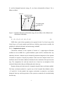
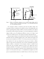
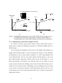
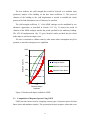
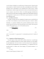
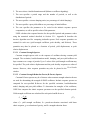
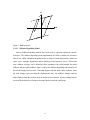
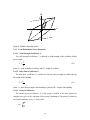
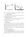
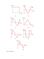
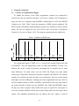
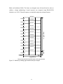
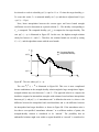
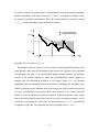
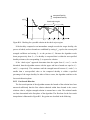
Several pulse types may be selected for the base input acceleration. These are shown
in Figure 10. The motions are specified using several parameters:
•
Pulse duration, t1: duration (in time) of the pulse acceleration.
•
Pulse amplitude, a1: peak value of pulse acceleration.
•
Computation time tRD: the duration over which the dynamic response is to be
calculated. The computation time must be greater than or equal to the pulse
duration. This creates two intervals of motion. Forced vibration occurs for 0 < t <
t1, and free vibration occurs for t > t1.
•
Number of cycles: Partial cycles may be applied by specifying non-integer values.
For example, for a half-cycle of a sine wave, 0.5 is specified for the number of
cycles.
41