1
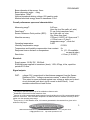
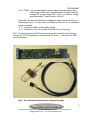
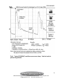
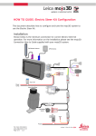
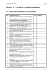
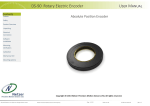
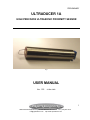
PRELIMINARY
ULTRADUCER 1A
HIGH PRECISION ULTRASONIC PROXIMITY SENSOR
Fig.1
USER MANUAL
Ver. 1.03
20-Dec-2006
1
1668 Lakehurst Rd.(Buckhorn), Lakefield K0L2H0 ON Canada Tel.: (705) 657-2419
[email protected] http://www.quansensor.com
PRELIMINARY
MANUFACTURED BY:
S&M Process Control Technology Inc.
1668 Lakehurst Rd.(Buckhorn), RR1 Lakefield K0L2H0 ON Canada
Tel.: (705) 657-2419
[email protected]
http://www.quansensor.com
Thank you for buying our proximity sensor!
INTRODUCTION
Ultraducer is a high precision non-contact analog through-air ultrasonic distance
sensor. It is designed for a wide range of industrial automation and control
applications requiring precise measurement of distances at short range.
The sensor is particularly suitable for applications that would typically require vernier
caliper precision and similar span, and be non-contact. Ultraducer can be regarded
as a non-contact “vernier caliper” replacement. The following applications could be
some of the most typical examples:
-
Positioning in CNC machining
Production line positioning
General purpose positioning gauge in robotics,
Fault detection in turning, milling and drilling production processes, ability to
penetrate through small holes (dia >1/4”)
Non-contact measurement of drill hole depths,
Non-contact measurement of sheet and foil thickness using pair of sensors,
Counting number of stacked up thin objects and thin sheets
Non-contact measuring of thickness of wires and bands.
Detection (on/off) of thin wires, threads and bands
Precise angular sensing (below 1.5deg)
Non-contact profiling of gently curved surfaces such as mirrors or lenses,
Verifying flatness of soft surfaces such as resins, coat of paint etc.
SPECIFICATIONS 1
Transducer
Transducer type: ultrasonic 1.45MHz
1
Preliminary and subject to change
2
1668 Lakehurst Rd.(Buckhorn), Lakefield K0L2H0 ON Canada Tel.: (705) 657-2419
[email protected] http://www.quansensor.com
PRELIMINARY
Beam diameter at the source: 8mm
Beam dispersion angle: ~1deg
Capacitance: 700pF
Nominal transducer driving voltage: 60V peak-to-peak
Maximal electrical energy stored in transducer: 0.5uJ
Overall performance specs and characteristics:
Measuring range2:
5-60 mm
(from the tip of the calib. ref. wire)
3
Dead band :
21 mm (from transducer face)
Sensor Reference Point position (SRP):
tip of the calib. ref. wire,
(typ.16mm from face).
Absolute accuracy:
+/-50um(+/-0.002”) at 2-4cm,const T.
+/-100um over +/-5 deg C
temperature range 4, const dist.
Operating temperature:
5-45C
Humidity compensation range:
0-100%
Temperature and humidity compensation time constant: 5s
Response time on distance or temperature:
1s (0.1-10s available
on special order)
Resolution:
+/-10um (+/-0.0005”)
Electrical:
Supply power: 19-29V DC, 50-60mA
Electrical power applied to transducer (burst): 1-5W, 60Vpp, t=6us, repetition
period=0.6-0.8ms.
Signal outputs:
DIST:
voltage 0-5V, proportional to the distance measured from the Sensor
Reference Point. Voltage conversion constant5 is about 50 mV/mm.
This output is zener-protected against over voltage or static and is shortcircuit protected (max short circuit current is about 50mA). Load
resistance should be at least 2kohm.
2
The range is specified from the tip of the calibration reference wire.
Deadband is measured from the transducer face.
4
Version 1A is fully compensated against speed of sound variation but not fully compensated against
electronic circuit drift. If the enclosure temperature is stabilized then the absolute accuracy is much
higher over the operating temp range.
5
It may vary by +/-20% between units; it is however guaranteed to be constant for a given unit to
within accuracy spec.
3
3
1668 Lakehurst Rd.(Buckhorn), Lakefield K0L2H0 ON Canada Tel.: (705) 657-2419
[email protected] http://www.quansensor.com
PRELIMINARY
PKSIG: Composite signal. AC component shows echo envelope (amplitude
versus time profile), and the average DC level indicates the air
temperature within the sensor’s field of view. The echo profile signal
has maximum amplitude of 500mV peak to peak (AC) and the AC
source impedance is 200 ohm. Typically 3 peaks should be visible (see
fig.3): one large initial peak is caused by transducer ring-down, the rising
edge of which marks the initial transmitter burst. This is followed by the
stationary calibration peak (at around 106us @ 25C, from the transmitter
burst) and that peak is then followed by the proper target echo peak.
The DC component has source impedance of 2kohm. The DC level can
be measured by a voltmeter of input impedance at least 2Mohm and
equipped with averaging (filtering) that is much longer than 1ms,
preferably above 100ms. Most DVM have intrinsic averaging built-in and
ignore the AC component when set in the V-DC range. Such voltmeters
can read and average the PKSIG DC level directly without any additional
filtering. If this signal is fed to a fast A/D converter then a filtering
capacitor >= 100uF/16V 6 should be connected in parallel.
Mechanical:
Transducer size:
cylindrical 16mm dia, 8mm height, radiating surface is circular
8mm dia.
Circuit board:
21 X 120mm double sided surface-mounted technology.
Enclosure7:
stainless steel (see Fig.1) or brass tubular, length =
130mm(5”), diameter 25mm (1”). Sealed and encapsulated
with epoxy resin.
CONNECTION DIAGRAM.
The unit is normally delivered all encapsulated in a tubular housing, including
transducer and circuit board. A 4-way screw-terminal block (J2-J3) is exposed at
the back end. Following connections are available, as labeled:
J3.1 = GND - common ground, this pin connects to the tubular enclosure
internally through a 100nF/50V capacitor.
J3.2 = +19… +29V DC, 60mA supply
J2.1 = DIST - distance, analog output signal, voltage 0-5V, (short circuit
current = 50mA)
6
This filtering cap should be connected only when temperature has to be monitored. It should be
disconnected when the AC component (echo profile) is to be viewed on a scope.
7
Normally delivered potted in a stainless steel or brass enclosure, optionally a bare board with a
transducer connected by a coaxial cable.
4
1668 Lakehurst Rd.(Buckhorn), Lakefield K0L2H0 ON Canada Tel.: (705) 657-2419
[email protected] http://www.quansensor.com
PRELIMINARY
J2.2 = PKSIG - echo profile signal for sensor adjustment and aiming using
oscilloscope in AC mode, and temperature T signal output (by
average DC voltage, range 0-5V). Note: T is inverted, voltage
goes down when T rises, at about -40mV/C.
Optionally, only the circuit board and transducer may be supplied, without a
housing (see fig.2). In such a case an additional connector J1 for transducer
leads is available.
J1.1 = Transducer GND (connect cable shield)
J1.2 = Transducer “live” (use coaxial cable RG179 up to 2m long)
Note: The steel enclosure is DC-floating and grounded internally for AC signals
through a 0.1uF/50V capacitor to shunt external RF noise. It can be tied to GND
lead if necessary.
Fig.2. Circuit board and transducer (without housing).
5
1668 Lakehurst Rd.(Buckhorn), Lakefield K0L2H0 ON Canada Tel.: (705) 657-2419
[email protected] http://www.quansensor.com
PRELIMINARY
Note: a shielded coaxial cable (recommended RG179), maximum 2m, should
be used to connect transducer with the board. Transducer has a 3-pin
2.5mm pitch header connection, the middle pin is “live” transmit/receive, and
the outer pins should both be tied to “Transducer GND” connection through a
cable shield.
Safety and hazardous approvals precautions:
Although the energy stored in transducer and the supply power (at 19V) is low
enough to conform to the Intrinsic Safety rules for hazardous applications,
this device was not yet submitted to regulatory approval agencies nor was it
tested against such approvals. No regulatory approval conformance is
claimed as of the date on this document.
LEGAL DISCLAIMER:
Ultraducer must not be used in hazardous application involving explosive
materials or when the explosion of substances such as gases, vapors, liquids
and powders may be present in the environment surrounding the sensor. If
the user installs Ultraducer in hazardous locations in spite of this note, it may
not hold the manufacturer and the vendor of this sensor responsible in case
of an accident.
SETTING AND AIMING PROCEDURE
Connect power leads and apply power. The unit will operate from 19 to 29 volts
drawing about 50mA, however it is recommended to operate it at the lower range of
the voltages (19-20V) in order to minimize the thermal drift caused by self-heating,
for the best accuracy.
Verify that the PKSIG (DC) voltage level is between 2.3 to 2.7 V at room
temperature (20-25C). The unit is normally set for PKSIG ~= 2.5V, however if the
calibration wire reference has been accidentally bent8 or moved, or if a new
transducer has been connected, then this voltage must be re-adjusted by
8
A stainless steel calibration reference wire is mounted at front of the sensor at typ 16mm distance
from the transducer face. On some transducers, the wire may be inclined or bent away from the
center axis, this is done intentionally in factory setup for the purpose of adjusting the amplitude of the
reference echo. This is NOT meant to be adjusted by a user! The wire is electrically unconnected.
6
1668 Lakehurst Rd.(Buckhorn), Lakefield K0L2H0 ON Canada Tel.: (705) 657-2419
[email protected] http://www.quansensor.com
PRELIMINARY
potentiometer P1 9 to the range indicated above. PKSIG DC level will vary
according to air temperature with the coefficient of about –40 to -60mV/C 10. Higher
air temperature means lower PKSIG(DC). The full span of PKSIG is 0 to 5V. It
does not depend on the target distance or on the presence of a target., but it does
depend on the position of the calibration reference wire11 .
Ensure that the target is a flat and smooth surface (roughness should be less than
0.1mm). For maximum range, use greater surfaces areas than the cross-section of
the beam (~1cm diameter at 6 cm distance).
Note: the distance is measured (and output through DIST) relative to the
reference which is the tip of the calibration wire!
Place the sensor such that the beam is striking the target surface at right angle,
within the accuracy of +/-0.3 deg (ideally). Connect oscilloscope probe between
GND and PKSIG output;use AC setting and trigger on the highest peak. Place a
target close to the maximal range envisaged for the application. Aim the sensor
direction in relation to the target in order to achieve the maximum height of the target
echo peak12. Alternatively, if an oscilloscope is not available, aim the sensor to
obtain the most stable voltage read on the DIST output. Once the sensor is
properly aimed, the normal to the target surface should be maintained within 0.3 deg
to the beam angle. If the surface inclination cannot be maintained constant, as is for
example the case with pivoted mountings, a small retrograde corner-cube reflector 13
should be fitted to the target to ensure that the reflected beam will always be
directed back to the sensor, along the same path. A typical target echo (see Fig.3)
should be above 50mV at DIST=4cm above the baseline noise level (use a scope
with averaging set on N=16). Detection threshold is about 25mV.
9
This applies only to units shipped without a housing.
The exact value may vary depending on the components and settings. It is however constant for a
given unit. This coefficient is not guarenteed to be factory-calibrated nor qualified.
11
Calibration reference wire is fixed and should not be user adjustable. If it is accidentally bent, it
may be repositioned. The criterium for the wire position is that the calibration echo be within 106+/-4
us from the rising edge of the transmitter pulse as seen on PKSIG(AC), at 2/3 height, and it’s
amplitude should be 100-150mV.
12
There should be at least three peaks normally visible: the first and the tallest broad peak coincides
with the initial transmitter burst and the ensuing ringdown of the transducer. The second peak is the
echo from the calibration reference wire placed at ~16mm at front of the transducer, and the third
peak is the proper target echo. The trace repeats with a period of about 0.6-0.8ms.
13
Retro-reflector consists of one unit of 3 perpendicular planes arranged in a corner, or an array of
such units. Example: back (embossed) side of a plastic bicycle light reflector .
10
7
1668 Lakehurst Rd.(Buckhorn), Lakefield K0L2H0 ON Canada Tel.: (705) 657-2419
[email protected] http://www.quansensor.com
PRELIMINARY
Fig.3. Typical PKSIG(AC) oscilloscope screen dump. Vertical scale is
pseudo-logarithmic.
8
1668 Lakehurst Rd.(Buckhorn), Lakefield K0L2H0 ON Canada Tel.: (705) 657-2419
[email protected] http://www.quansensor.com
PRELIMINARY
Restrictions.
As is the case with all or almost all ultrasonic sensors, Ultraducer is sensitive
to environment and its accuracy and range may be adversely affected by gases and
vapors as well as reduced atmospheric pressure or very strong airflow and
turbulence. Ultrasonic sensors cannot work in vacuum.
Examples of less suitable or unsuitable applications are:
-
high contents of CO2, CFC and hydrocarbon gases and vapors;
-
temperatures above 45deg C or below 5 degC (extended temperature range
version is available on special order), and long range sensing beyond 10cm
(extended range version is also available on special order);
-
under strong and turbulent airflow or strong temperature gradient within the
target range or a gradient between the target and the sensor, may exhibit
reduced accuracy;
-
very strong vibrations (in such a case the sensor should be mounted on
shock-absorbing rubber pads or grommets);
-
very strong RF noise in the1-2MHz range (in such a case the sensor has to
be shielded, the supply and the signal leads have to be passed through an
RF filters).
9
1668 Lakehurst Rd.(Buckhorn), Lakefield K0L2H0 ON Canada Tel.: (705) 657-2419
[email protected] http://www.quansensor.com