1
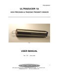
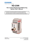
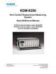
Home
Noncontact Displacement Measuring
System User’s Manual
1.23 (31.24)
.984
(24.99)
Copyright © 1998
PART NO: 860135-001
Rev. B
Kaman InstrumentationOperations
3450 North Nevada Avenue
Colorado Springs, CO 80907
www.kamaninstrumentation.com or 719-635-6979
PIN SIGNAL
2 SWITCH
3 SWITCH
4,7 V IN
5 COMM
9 V OUT
KD 2440
KAMAN
2.357
(59.9) 1.902
(48.3)
Instrumentation
This apparatus, when installed and operated per the manufacturer’s recommendations, conforms
with the protection requirements of EC Council Directive 89/336/EEC on the approximation of the
laws of the member states relating to Electromagnetic Compatibility. Please refer to the KD-2440
Declaration of Conformity or contact Kaman Precision Products for details.
.610
(15.5)
Home
•
•
•
•
KD-2440 Unit
The KD-2440 system consists of three subassemblies:
the sensor with integrated cable, the signal conditioning
electronics module, and the power and output cable.
The KD-2440 electronics uses a standard DB-9
connector to bring +12 Vdc to +24 Vdc into the
electronics and provide outputs for the analog voltage
and switch functions.
1
2
6
3
7
4
8
5
9
Electronics DB-9
Connector Face
5
4
9
3
8
2
7
1
6
ORN
CLR
Mounting the KD-2440 electronics module can be done
using either of the two holes in the enclosure, and an M3 or 4 screw. It is preferable not to remove both screws
from the case for mounting purposes. An easier
mounting method may be to use a cable tie wrap or zip
tie.
Positioning the electronics module so that it is not the
low point in the cable will keep liquids from running
down the cable and into the electronics. Take care to
route the sensor cable to avoid crushing or crimping it
during use. Damage to the sensor cable may affect the
desired set points and overall operation of the
electronics.
I/O Cable DB-9
Connector Face
Theory of Operation
The KD-2440 system operates on a traditional Colpitts
oscillator circuit where the sensor acts as the resonating
coil for the oscillator. The proximity of the target to the
sensor face pulls the oscillator, changing its frequency
and amplitude of modulation, controlling a variable gain
oscillator section within the electronic circuit.
10
12Vdc High Gain
9
12Vdc Low Gain
7
24Vdc Low Gain
5
3
50
100
6
Aluminum
4
303 Stainless
2
150
4130 Steel
0
Displacement, Mils
14
10
12 Vdc High Gain
8
6
24 Vdc Low Gain
4
12 Vdc Low Gain
2
12
10
8
6
Aluminum
4
303 Stainless
2
4130 Steel
0
0
0
50
100
Displacement, Mils
150
14
24 Vdc High Gain
12
50
100
Displacement, Mils
Outputs at Medium Gain & 24 Volt Input
303 SS Output for 12 & 24V Inputs
0
150
50
100
Displacement, Mils
150
Example Output Noise @ 12Vdc Input, Mid
Gain, Medium Displacement
0.80
4130 Steel
0.70
Aluminum
0.60
304 Stainless
0.50
0.40
0.30
0.20
0.10
0.00
100
1000
10000
Bandwidth, Hz
4130 Steel Output for 12 & 24 Volt Inputs
18
24 Vdc High Gain
16
14
12 Vdc High Gain
12
10
8
6
24 Vdc Low Gain
4
12 Vdc Low Gain
2
0
0
50
100
150
Displacement, Mils
5CM Sensor Response Data:
5CM Sensor Response Data:
2
8
0
0
The KD-2440 electronics has two potentiometers
accessible through openings in the enclosure for
adjusting the GAIN and SWITCH SET POINT level.
Mounting Instructions
24Vdc High Gain
11
1
Electronics
An LED indicates when the optically-isolated switch is in
the closed position. The KD-2440
electronics and sensors utilize SMA type coaxial
connectors: female on the electronics, and male on the
sensor cable. Two production-sensor configurations
are available, the 9C and the 5CM. Data for these two
sensors is shown on the following pages. The sensor
must be attached snugly (finger tight) to the electronics
assembly for the unit to function properly.
Outputs at Medium Gain & 12 Volt Input
12
DC Output Voltage
Outstanding Precision: Static Resolution to 12
Microinches
Easy to Adjust
Excellent Performance with Ferrous Targets
Variable Voltage Input from 12 to 24 Volts DC
Adjustable Gain for up to 22 Volts Output with 24
Volts Input
Compact Rugged Electronics and Sensors
Temperature Tolerant Sensors (to 400°F)
Level Adjustable Switched Output to 10Khz for
Process Control
Drop in Replacement to Kaman’s KD-2400 with
Accessories Kit
Aluminum Output for 12 & 24 Volt Inputs
13
DC Output Voltage
•
•
•
•
RED
Signal
N/C
SWITCH RX
SWITCH TX
VIN (ALTERNATE)
COMM
N/C
VIN
N/C
VOUT
CABLE SHIELD
Differential Noise, mV p-p
•
BLU
WHT
GRN
BLK
Pin
1
2
3
4
5
6
7
8
9
-
DC Output Voltage
Features Summary / Advantages
Wire Color
DC Output Voltage
Kaman Precision Products’ Displacement Measuring
System Model KD-2440 is a noncontact linear proximity
measuring system. This low-cost, easy-to-use system
makes precision static and dynamic measurements of
metal targets, and thickness measurements of nonconductive material backed by metal. The system
includes a switching output that will track RPM
measurement to 10Khz.
DB-9 Connections and Power I/O Cable
Color Chart:
DC Output Voltage
KD-2440
7
Home
9C Sensor Response Data:
12 Vdc High Gain
8
6
24 Vdc Low Gain
12 Vdc Low Gain
4
2
0
0
50
100
150
200
Displacement, Mils
6
12 Vdc Low Gain
4
2
0
0
50
100
150
200
Displacement, Mils
250
DC Output Voltage
4130 Steel Output for 12 & 24 Volt Inputs
14
24 Vdc High Gain
12
10
12 Vdc High Gain
8
6
4
24 Vdc Low Gain
12 Vdc Low Gain
2
0
0
50
100
150
200
Displacement, Mils
250
6
12V in Aluminum
12V in 303 Stainless
2
12V in 4130 Steel
0
50
100
150
200
Displacement, Mils
250
10
DC Output Voltage
12 Vdc High Gain
24 Vdc Low Gain
8
4
Outputs at Medium Gain & 24 Volt Input
12
8
6
4
1. Adjust the sensor / target to its maximum
displacement, plus the offset, plus approximately
20% of the range (.058”).
2. Adjust the gain potentiometer to its minimum point
(adjust clockwise until the analog output saturates)
3. Slowly increase the gain potentiometer (counter
clockwise) until it saturates at its maximum point.
this will be approximately two volts below the input
voltage.
4. At this point, the module is calibrated to a
maximum output per displacement condition. As
the sensor is moved toward the target from
approximately .058”, the output will decrease. If the
sensor / target displacement is increased beyond
.058”, the output will saturate at approximately two
volts below the input.
The gain (ratio of output voltage to target
displacement) is used to adjust the output slope
(output per displacement). When changing types of
target materials or power supply voltages, it will be
necessary to readjust the gain for the desired
output voltage.
The KD-2440 can easily be adjusted or “calibrated”
to obtain maximum output per displacement,
maximum range, or any variation in between. Note
that when the KD-2440 is adjusted for maximum
output per displacement, it is at a minimum usable
range, whereas a minimum gain gives a voltage
change throughout the largest displacement for the
same sensor, target, and range as depicted in the
following graph:
24V in Aluminum
24V in 303 Stainless
2
24V in 4130 Steel
0
0
50
100
150
200
Displacement, Mils
250
Example Output Noise @ 12Vdc Input, Mid
Gain, Medium Displacement
4.00
4130 Steel
3.50
304 Stainless
3.00
2.50
Aluminum
2.00
1.50
1.00
0.50
0.00
100
1000
10000
Bandwidth, Hz
Differential Noise, mV p-p
DC Output Voltage
10
6
0
24 Vdc High Gain
Adjustment and Calibration
The KD-2440 is instrumented with a ten volt
regulator to provide a clean repeatable output
signal. The input voltage must be maintained at a
minimum of twelve volts for the regulator to
function.
8
250
303 SS Output for 12 & 24 Volt Input
14
12
10
saturation (the output begins to change with a gain
increase).
DC Output Voltage
10
Outputs at Medium Gain & 12 Volt Input
12
DC Output Voltage
DC Output Voltage
Aluminum Output for 12 & 24 Volt Input
14
24 Vdc High Gain
12
The signal is half-wave rectified and filtered to
obtain an analog voltage proportional to the target
position or displacement. The analog voltage
output can be varied by adjustment of the gain. The
input power is diode protected and regulated to
provide a clean low-noise signal. The output is
short-circuit current protected.
4130 Steel Output for 12 & 24 Volt Inputs
18
24 volt input w ith high gain
16
14
To maximize the output slope for an application using a
5CM sensor with a .010” offset and a range of .040”,
follow these steps:
Switched Output Operation
The KD-2440’s switched output is a simple on / off
switch with a corresponding LED indicator lamp. The
switch is in a closed condition when the LED is
illuminated. The switch can be adjusted to trip
anywhere along the sensor range using the “Switch
Setpoint” potentiometer.
CLEANING
12 volt input w ith
high gain
12
Example Calibration
10
8
The KD-2440 is not designed to be immersed or
operated while immersed in liquids. Solvents may
damage electronics module, sensor, or power I/O
cable. Clean the unit with a damp cloth.
EMI PERFORMANCE
6
12 or 24 volt input
w ith low gain
4
2
0
0
50
100
Displacement, Mils
150
The minimum gain is defined as being the lowest
gain obtainable without pulling the circuit into
saturation. Minimum gain can be obtained by
setting the sensor displacement to a point within
the usable range (preferably mid range), then
slowly decreasing the gain potentiometer
(clockwise) until the output saturates. At this point,
increase the gain slightly to a point just above
The KD-2440 conforms with the applicable standards
of Council Directive for Generic for Light Industrial and
Commercial Use. Under some EMI environments, at
specific frequencies, the KD-2440 unit may experience
a change in output voltage. In general, when exposed
to those environments covered by the EMC directive,
the user can expect less than 5% deviation of output.
Contact Kaman Instrumentation for specific data or for
recommended solutions if you experience problems
with the KD-2440.
3
Home
KD-2440
9C Sensor Specifications:
Specifications
RG179 coax cable
.320 Dia
(8.13)
3/8-24 THD
ELECTRICAL
1.030 (26.16)
SMA Male Connector
INPUT
1.250 (31.75)
Voltage: Regulated 12 VDC to 24 VDC
Current: Fuse limit input current from power source to 11 mA, .28W maximum at full load
ANALOG OUTPUT
Current (Full load): 4.2 mA maximum
Impedance: 50 ohms
Voltage: 0-22 VDC minimum with 24 VDC input
0-10 VDC minimum with 12 VDC input
SWITCHED OUTPUT
Opto-Isolated
Load Current: 100 mA maximum AC or DC
Load Voltage: 30V rms, 42.4V peak, or 60Vdc
On Resistance: 30 ohms minimum / 50 ohms maximum
Switch Point Hysterisis: 0.56% of full scale for 9C sensor, and 0.97% of full scale for 5CM sensor, using
24Vdc input on 4130 steel.
FREQUENCY RESPONSE
0-10 KHz (± 3db)
96 (2438)
Target Material
Non-Ferrous (Aluminum)
Non-Magnetic Steels (304
Stainless)
Magnetic Steels (4130)
9C Sensor Measuring Range
0 - 0.175 in.
(0 - 4.45 mm)
0.025 - 0.200 in.
(0.64 - 5.08 mm)
0.040 - 0.275 in.
(1.02 - 6.99 mm)
5CM Sensor Specifications:
RESOLUTION
Better than 0.008% of measuring range using a 5CM sensor on a 4130 steel target at mid scale, and
12Vdc input
M5 x 0.8 THD
RG179 coax cable
.160 Dia.
(4.1)
ENVIRONMENTAL
SMA Male Connector
ENCLOSURE RATINGS
Sensor: IP 67
Electronics: IP 61
1.60 (40.6)
1.85 (47.0)
120 (3048)
OPERATING TEMPERATURE RANGE
Sensor and cable: 0°F to 400°F (-18°C to 205°C)
Electronics: 32°F to 150°F (0°C to 66°C)
STORAGE TEMPERATURE RANGE
Sensor and cable: -60°F to 400°F (-52°C to 205°C)
Electronics: -58°F to 212°F (-50°C to 100°C)
Target Material
Non-Ferrous (Aluminum)
Non-Magnetic Steels (304
Stainless)
Magnetic Steels (4130)
5CM Sensor Measuring Range
0 - 0.100 in.
(0 - 2.54 mm)
0.010 - 0.125 in.
(0.254 - 3.18 mm)
0.015 - 0.150 in.
THERMAL DRIFT
Less than 0.22% per °C of full scale for sensor, electronics or system.
Dimensions are in inches (millimeters)
4
5
(0.38 - 3.8 mm)
Home
9C Sensor Response Data:
12 Vdc High Gain
8
6
24 Vdc Low Gain
12 Vdc Low Gain
4
2
0
0
50
100
150
200
Displacement, Mils
6
12 Vdc Low Gain
4
2
0
0
50
100
150
200
Displacement, Mils
250
DC Output Voltage
4130 Steel Output for 12 & 24 Volt Inputs
14
24 Vdc High Gain
12
10
12 Vdc High Gain
8
6
4
24 Vdc Low Gain
12 Vdc Low Gain
2
0
0
50
100
150
200
Displacement, Mils
250
6
12V in Aluminum
12V in 303 Stainless
2
12V in 4130 Steel
0
50
100
150
200
Displacement, Mils
250
10
DC Output Voltage
12 Vdc High Gain
24 Vdc Low Gain
8
4
Outputs at Medium Gain & 24 Volt Input
12
8
6
4
1. Adjust the sensor / target to its maximum
displacement, plus the offset, plus approximately
20% of the range (.058”).
2. Adjust the gain potentiometer to its minimum point
(adjust clockwise until the analog output saturates)
3. Slowly increase the gain potentiometer (counter
clockwise) until it saturates at its maximum point.
this will be approximately two volts below the input
voltage.
4. At this point, the module is calibrated to a
maximum output per displacement condition. As
the sensor is moved toward the target from
approximately .058”, the output will decrease. If the
sensor / target displacement is increased beyond
.058”, the output will saturate at approximately two
volts below the input.
The gain (ratio of output voltage to target
displacement) is used to adjust the output slope
(output per displacement). When changing types of
target materials or power supply voltages, it will be
necessary to readjust the gain for the desired
output voltage.
The KD-2440 can easily be adjusted or “calibrated”
to obtain maximum output per displacement,
maximum range, or any variation in between. Note
that when the KD-2440 is adjusted for maximum
output per displacement, it is at a minimum usable
range, whereas a minimum gain gives a voltage
change throughout the largest displacement for the
same sensor, target, and range as depicted in the
following graph:
24V in Aluminum
24V in 303 Stainless
2
24V in 4130 Steel
0
0
50
100
150
200
Displacement, Mils
250
Example Output Noise @ 12Vdc Input, Mid
Gain, Medium Displacement
4.00
4130 Steel
3.50
304 Stainless
3.00
2.50
Aluminum
2.00
1.50
1.00
0.50
0.00
100
1000
10000
Bandwidth, Hz
Differential Noise, mV p-p
DC Output Voltage
10
6
0
24 Vdc High Gain
Adjustment and Calibration
The KD-2440 is instrumented with a ten volt
regulator to provide a clean repeatable output
signal. The input voltage must be maintained at a
minimum of twelve volts for the regulator to
function.
8
250
303 SS Output for 12 & 24 Volt Input
14
12
10
saturation (the output begins to change with a gain
increase).
DC Output Voltage
10
Outputs at Medium Gain & 12 Volt Input
12
DC Output Voltage
DC Output Voltage
Aluminum Output for 12 & 24 Volt Input
14
24 Vdc High Gain
12
The signal is half-wave rectified and filtered to
obtain an analog voltage proportional to the target
position or displacement. The analog voltage
output can be varied by adjustment of the gain. The
input power is diode protected and regulated to
provide a clean low-noise signal. The output is
short-circuit current protected.
4130 Steel Output for 12 & 24 Volt Inputs
18
24 volt input w ith high gain
16
14
To maximize the output slope for an application using a
5CM sensor with a .010” offset and a range of .040”,
follow these steps:
Switched Output Operation
The KD-2440’s switched output is a simple on / off
switch with a corresponding LED indicator lamp. The
switch is in a closed condition when the LED is
illuminated. The switch can be adjusted to trip
anywhere along the sensor range using the “Switch
Setpoint” potentiometer.
CLEANING
12 volt input w ith
high gain
12
Example Calibration
10
8
The KD-2440 is not designed to be immersed or
operated while immersed in liquids. Solvents may
damage electronics module, sensor, or power I/O
cable. Clean the unit with a damp cloth.
EMI PERFORMANCE
6
12 or 24 volt input
w ith low gain
4
2
0
0
50
100
Displacement, Mils
150
The minimum gain is defined as being the lowest
gain obtainable without pulling the circuit into
saturation. Minimum gain can be obtained by
setting the sensor displacement to a point within
the usable range (preferably mid range), then
slowly decreasing the gain potentiometer
(clockwise) until the output saturates. At this point,
increase the gain slightly to a point just above
The KD-2440 conforms with the applicable standards
of Council Directive for Generic for Light Industrial and
Commercial Use. Under some EMI environments, at
specific frequencies, the KD-2440 unit may experience
a change in output voltage. In general, when exposed
to those environments covered by the EMC directive,
the user can expect less than 5% deviation of output.
Contact Kaman Instrumentation for specific data or for
recommended solutions if you experience problems
with the KD-2440.
3
Home
•
•
•
•
KD-2440 Unit
The KD-2440 system consists of three subassemblies:
the sensor with integrated cable, the signal conditioning
electronics module, and the power and output cable.
The KD-2440 electronics uses a standard DB-9
connector to bring +12 Vdc to +24 Vdc into the
electronics and provide outputs for the analog voltage
and switch functions.
1
2
6
3
7
4
8
5
9
Electronics DB-9
Connector Face
5
4
9
3
8
2
7
1
6
ORN
CLR
Mounting the KD-2440 electronics module can be done
using either of the two holes in the enclosure, and an M3 or 4 screw. It is preferable not to remove both screws
from the case for mounting purposes. An easier
mounting method may be to use a cable tie wrap or zip
tie.
Positioning the electronics module so that it is not the
low point in the cable will keep liquids from running
down the cable and into the electronics. Take care to
route the sensor cable to avoid crushing or crimping it
during use. Damage to the sensor cable may affect the
desired set points and overall operation of the
electronics.
I/O Cable DB-9
Connector Face
Theory of Operation
The KD-2440 system operates on a traditional Colpitts
oscillator circuit where the sensor acts as the resonating
coil for the oscillator. The proximity of the target to the
sensor face pulls the oscillator, changing its frequency
and amplitude of modulation, controlling a variable gain
oscillator section within the electronic circuit.
10
12Vdc High Gain
9
12Vdc Low Gain
7
24Vdc Low Gain
5
3
50
100
6
Aluminum
4
303 Stainless
2
150
4130 Steel
0
Displacement, Mils
14
10
12 Vdc High Gain
8
6
24 Vdc Low Gain
4
12 Vdc Low Gain
2
12
10
8
6
Aluminum
4
303 Stainless
2
4130 Steel
0
0
0
50
100
Displacement, Mils
150
14
24 Vdc High Gain
12
50
100
Displacement, Mils
Outputs at Medium Gain & 24 Volt Input
303 SS Output for 12 & 24V Inputs
0
150
50
100
Displacement, Mils
150
Example Output Noise @ 12Vdc Input, Mid
Gain, Medium Displacement
0.80
4130 Steel
0.70
Aluminum
0.60
304 Stainless
0.50
0.40
0.30
0.20
0.10
0.00
100
1000
10000
Bandwidth, Hz
4130 Steel Output for 12 & 24 Volt Inputs
18
24 Vdc High Gain
16
14
12 Vdc High Gain
12
10
8
6
24 Vdc Low Gain
4
12 Vdc Low Gain
2
0
0
50
100
150
Displacement, Mils
5CM Sensor Response Data:
5CM Sensor Response Data:
2
8
0
0
The KD-2440 electronics has two potentiometers
accessible through openings in the enclosure for
adjusting the GAIN and SWITCH SET POINT level.
Mounting Instructions
24Vdc High Gain
11
1
Electronics
An LED indicates when the optically-isolated switch is in
the closed position. The KD-2440
electronics and sensors utilize SMA type coaxial
connectors: female on the electronics, and male on the
sensor cable. Two production-sensor configurations
are available, the 9C and the 5CM. Data for these two
sensors is shown on the following pages. The sensor
must be attached snugly (finger tight) to the electronics
assembly for the unit to function properly.
Outputs at Medium Gain & 12 Volt Input
12
DC Output Voltage
Outstanding Precision: Static Resolution to 12
Microinches
Easy to Adjust
Excellent Performance with Ferrous Targets
Variable Voltage Input from 12 to 24 Volts DC
Adjustable Gain for up to 22 Volts Output with 24
Volts Input
Compact Rugged Electronics and Sensors
Temperature Tolerant Sensors (to 400°F)
Level Adjustable Switched Output to 10Khz for
Process Control
Drop in Replacement to Kaman’s KD-2400 with
Accessories Kit
Aluminum Output for 12 & 24 Volt Inputs
13
DC Output Voltage
•
•
•
•
RED
Signal
N/C
SWITCH RX
SWITCH TX
VIN (ALTERNATE)
COMM
N/C
VIN
N/C
VOUT
CABLE SHIELD
Differential Noise, mV p-p
•
BLU
WHT
GRN
BLK
Pin
1
2
3
4
5
6
7
8
9
-
DC Output Voltage
Features Summary / Advantages
Wire Color
DC Output Voltage
Kaman Instrumentation’s Displacement Measuring
System Model KD-2440 is a noncontact linear proximity
measuring system. This low-cost, easy-to-use system
makes precision static and dynamic measurements of
metal targets, and thickness measurements of nonconductive material backed by metal. The system
includes a switching output that will track RPM
measurement to 10Khz.
DB-9 Connections and Power I/O Cable
Color Chart:
DC Output Voltage
KD-2440
7