1
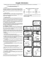
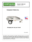
Welcome to the ROADMASTER family!
This manual has been prepared to acquaint you with the installation, operation, care and maintenance of your A-frame, and
to provide you with important safety information.
Read your owner’s manual cover to cover. Understand how to install and operate your A-frame, and carefully follow
the instructions and safety precautions.
We thank you for your patronage and greatly appreciate your discerning taste.
Contents
Save this manual
Safe towing practices......................................................1
Connecting and disconnecting
Connecting the A-frame...........................................2-3
Disconnecting the A-frame.......................................3-4
Care and cleaning...........................................................4
Coupler information.........................................................5
Limited warranty..............................................................6
Optional equipment and accessories...............................7
Save this manual for future reference. It contains important sections relative to safety, use, maintenance and
other information. Therefore, make sure this manual is
always with you when you’re towing.
You may download or print a copy of the most current
manual at www.roadmasterinc.com (under ‘Support').
Your A-frame serial number…
…is located on the interior of one of the A-frame arms.
Write down the serial number in the space below and
retain for future reference.
Serial number:
All illustrations and specifications contained herein are based on the latest
information available at the time of publication. ROADMASTER, Inc. reserves
the right to make changes, at any time, without notice, in material, specifications and models, or to discontinue models.
Read all instructions before installing
the A-frame, or before towing a vehicle.
Failure to understand how to properly install or operate the A-frame could result
in property damage, personal injury or
even death.
Safe towing practices
To ensure your safety and that of your passengers, as
well as the safety of others on the road, follow these safe
towing practices at all times.
CAUTION
ROADMASTER recommends reversing with the
towed vehicle attached be kept to a minimum, and
only as a necessity.
Backing up with the towed vehicle attached may
cause the towed vehicle to “jackknife,” which could
cause non-warranty damage the A-frame.
• Be sure the vehicle can be towed before taking it on
the road. Failure to properly equip the vehicle will cause
severe damage to the transmission or the transaxle, unless
the vehicle’s manufacturer has approved the vehicle for
flat towing. If this is the case, check the vehicle’s owner’s
manual for the proper procedure(s) to prepare the vehicle
for towing.
• The A-frame must be approximately level with the
ball hook on the motorhome — no more than four inches
above or below level.
Towing with the A-frame at a severe upward or downward slope may force the coupler off the ball hook on
sharp inclines or declines.
• The steering wheel must be unlocked and free to
turn when towing. Failure to do so can cause severe tire
and equipment damage.
• The TowMaster A-frame is rated at a maximum of 1,700
kilograms carrying capacity; therefore the weight of the
towed vehicle and all its contents cannot exceed 1,700
kilograms.
• The A-frame must be properly secured with pins
before towing. Unless the A-frame is secured to both
vehicles with all appropriate pins, the towed vehicle will
detach.
• Inspect the system before towing — if any component
is damaged, replace
ball
it before towing. Also,
Figure 1
clamp
check the coupler ball
clamp and ball socket
(Figure 1) for fractures
or cracks in the steel.
• This A-frame is
designed for use on
ball
socket
paved roads only.
ROADMASTER does
not recommend off-road towing, nor does ROADMASTER
warrant the A-frame for off-road use.
• Never tow a vehicle with one of a comparable
weight. The towed vehicle’s weight should never exceed
40 percent of the towing vehicle’s weight.
Towing a vehicle with one of similar weight will cause
the towed vehicle to override the towing vehicle, resulting
in “jackknifing.” Serious damage to both vehicles, as well
as the towing system could result.
• Always stand to one side and as close to the motorhome as possible when releasing the A-frame locking
mechanisms. Never stand between the adjustable arms,
or put any part of your body between the adjustable arms,
when releasing the A-frame — the towed vehicle may lurch
forward when the locking mechanisms are released.
• Check the motorhome turning radius. Some motorhome chassis have such a tight turning radius that the
motorhome can hit the towed vehicle. Before getting on
the road with your towed vehicle, you should test your
turning radius in an empty parking lot.
• Keep the A-frame clean and well-lubricated. As is
the case with most precision equipment, frequent cleaning
and care results in better performance and longevity.
Refer to the section titled “Care and cleaning” for further
information.
Failure to follow these instructions may cause property damage, personal injury or even death.
1
Connecting the A-frame
Center and adjust the A-frame
Note: it is only necessary to center and adjust the Aframe once for any particular vehicle.
1. Insert both of the towing arms (Figure 2) through the
holes in the towed vehicle’s fascia and into the threaded
holes in the bumper core. Tighten them as much as possible without using a wrench.
Then, as shown in Figure 2, unthread each towing arm
just enough so that the holes at the end are parallel with
the ground.
2. Holding both of the A-frame arms together, attach either
arm to its corresponding towing arm with the included linch
pin (Figure 3).
3. Extend the other arm across the towed vehicle and
attach it to the other towing arm.
4. Pull the coupler (and the two A-frame arms with it)
away from the towed vehicle, as far as they will go. The
coupler must be approximately centered between the towing arms on the bumper core.
Both Autowloks (Figure 3) will engage — the buttons
will pop up.
5. Using a torque wrench, tighten the two bolts at the
yoke (Figure 3) to 57 ft./lbs. (77 N-M).
6. The A-frame is now centered and adjusted to your
towed vehicle.
If you wish to tow a different vehicle with the A-frame,
untighten the two yoke bolts and repeat the steps above.
To connect the A-frame for towing, follow the steps
below.
Connecting the A-frame for towing
1. Drive the towed vehicle within three or three-and-a-half
feet of the motorhome.
Put the vehicle in gear (park), set the emergency brake
and chock one of the wheels.
2. Connect both A-frame arms to the towing arms with
the included linch pins.
3. Lift the coupler up and move it forward or backward,
as needed, to maneuver it over the ball hook.
If one of the A-frame arms does not slide forward or
backward, press down on the Autowlok button to unlock
it.
4. Press and hold the coupler locking trigger (Figure 4)
and lift the handle (Figure 4) up.
Lower the coupler over the ball hook so that it completely covers it; release the handle.
5. Be certain the coupler is properly locked onto the ball
hook — the handle must be completely lowered, as shown
in Figure 4, with the coupler completely covering the ball
hook, for the coupler to be locked onto the ball hook.
If the coupler is not properly locked onto the ball
hook, as described above, it will release during towing.
The A-frame will separate from the motorhome, which
may cause property damage, personal injury or even
death.
continued on next page
2
Figure 2
Figure 3
Figure 4
Connecting the A-frame
c ontinued from preceding page
6. Plug in the lighting power cord, according to the supplier’s instructions and verify that all lighting systems are
functioning.
Before towing the vehicle, make certain that the steering is unlocked, the transmission is in the proper setting,
and the emergency brake is released. Remove the wheel
chock.
Check the owner’s manual for the proper towing procedures or requirement(s) for the vehicle to be towed.
Do not tow a vehicle with a ball hook or any supplementary equipment rated less than the actual weight
of the towed vehicle and all its contents.
If any supplementary towing equipment is not rated
at the weight of the towed vehicle and all its contents
it may fail during towing, causing property damage,
personal injury or even death.
Do not tow the vehicle until the A-frame is properly
attached with all pins, or the vehicle will detach, which
may cause property damage, personal injury or even
death.
When you drive away, steer briefly to the left and then
to the right, to extend, self-center and lock the A-frame. Always stop at this time. Check the A-frame to ensure
that both arms are locked, before assuming highway
speed. Additionally, check the other components of your
towing system, to ensure that they are fully engaged.
Both A-frame arms must be locked before towing.
If they are not, the momentum of the towed vehicle
will apply excessive force to the A-frame arms and
other components of the towing system, which may
cause the towing system to fail, resulting in property
damage, personal injury or even death.
Disconnecting the A-frame
1. Disconnecting the A-frame is essentially the reverse
of connecting it.
Before you begin, always try to park on level ground,
with the towed vehicle in line with the motorhome. This will
eliminate most of the tension between the two vehicles,
allowing for an easier disconnect.
2. Chock one of the wheels, to prevent a runaway vehicle.
3.Push down on the Autowlok buttons to release the
locking mechanisms.
Figure 5
When the locking mechanisms are released, the
towed vehicle may surge forward. For this reason,
always stand to one side when disconnecting the Aframe. Never stand between the adjustable arms, or
put any part of your body between the adjustable arms.
CAUTION
Never use a hammer or mallet to disconnect the
Autowlok buttons. The A-frame arms will not automatically lock if the Autowlok buttons are damaged.
4. Pull back on the coupler locking trigger and lift the
handle (Figure 4) to release the coupler. Lift the coupler
off the ball hook.
Note: if you must park on an uphill incline, you may
find that you cannot release the coupler even with the
Autowlok buttons released. The weight of the towed vehicle trying to roll back (Figure 5) is binding the coupler
in place.
Allow the towed vehicle to idle forward just enough to
continued on next page
3
Disconnecting the A-frame
continued from previous page
take the tension of this weight off the coupler. Then hold
the vehicle in position by first applying the emergency
brake, then shifting into park.
Once the tension is off, pull back on the coupler locking
lever to release the coupler.
5. Pull the linch pins from both of the A-frame arms to
disconnect them; collapse the arms.
6. Store the A-frame in any covered location that will
protect it from the elements.
Care and cleaning
As is the case with most precision equipment, frequent
cleaning and care results in better performance and longevity. Use the following guidelines to keep your A-frame
clean and well-lubricated.
Always clean the A-frame before lubricating. Use a
water-soluble cleaner such as Voom RV (part number
9911) — it does an exceptional job of breaking down road
film, dirt and grease.
CAUTION
Do not use petroleum-based products to clean or
lubricate the A-frame. Petroleum will attract dirt and
dust, which will make the arms difficult to slide.
Clean all moving components, paying special attention
to the inner arms and the locking mechanisms. Spray a
liberal amount of cleaner on the inner arms and into the
Autowlok buttons (Figure 3). Then, spray cleaner into the
hole under each Autowlok button. Push and release each
button, to work the cleaner into the locking mechanism.
Push each Autowlok button down, and retract and extend
each A-frame arm several times. As the arm closes, the
cleaner will lift dirt and debris from the interior of the outer
4
arm and the locking mechanism. Wipe the dirt and debris
off and repeat, if necessary, until each arm is clean.
After cleaning the A-frame, wipe any remaining cleaner
away.
Now that you have a clean, dry A-frame, use a dry
silicone aerosol, such as LubeMaster (part number 747),
to lubricate the A-frame — spray a liberal amount of silicone into all moving components, including the Autowlok
buttons.
Flex the A-frame components, and push and release
the Autowlok buttons, to work the lubricant in.
CAUTION
Always clean the locking mechanisms, as described
above, before lubricating them. Silicone coats and covers in a thin layer. If it is not removed, it will reduce
the clearance for the locking mechanisms, preventing
proper operation.
Lubricate the coupler ball socket and ball clamp. The
manufacturer’s instructions are on the next page
Coupler information
Following are the coupler manufacturer’s operation, latching and maintenance instructions, for your reference.
Assembling, operating and maintenance instruction
of coupling heads ZSK and BC type
1.Introduction
Coupling heads are made in accordance with the Directive 94/20/EWG and the Regulations ECE-R55. Coupling heads are of great importance for road safety, therefore numerous tests have been carried out to confirm their reliability. Nevertheless, to ensure
their reliability it is essential that coupling heads are properly assembled, operated and
maintained. Therefore, please read this instruction very carefully and follow all the directions.
2. Range of application
Coupling heads can be used only with those trailers where the required parameters
marked on the trailer casing have not been exceeded. All coupling heads are to be
coupled with A class tow-hook balls (50 mm in diameter) that are made in accordance
with the Directive 94/20/EWG and the Regulations ECE-R55.
Ranges of rotation — see Figure A
3. Assembling instruction
A coupling head should be fastened so that the coupling point of the trailer (with horizontal positioning of the bodywork, the maximum permissible “Pmax” axle load and properly
placed load) does not exceed the permissible S value (vertical thrust) engraved on the
body of the coupling head, and is 430 ±35 mm above the surface of the tyre adhesion
to the ground — see Figure B. All deviations must be taken into consideration when
approving the trailer construction. Coupling heads (depending on a design) may be fastened onto pipe shafts (round or square), V-shaped shafts and inertia brake couplings.
3.1. Assembling to a pipe shaft (round or square)
The casing of the coupling head should be placed on the shaft, properly positioned to the
holes and screwed down with 2 bolts, 2 self-retaining nuts, 4 washers and 2 distancing
jointing sleeves — see Figure C. When there are three vertical fastening holes, only two
are to be used i.e. the front fastening hole and one of the rear ones.
3.2. Assembling to a V-shaped shaft
The recommended way of fastening the coupling heads of ZSK-750K and BC-800L
type to a V-shaped shaft with steel sections that are up to 24 mm wide and up to 60 mm
high with the use of a connector, horizontally placed 4 fastening screws M12x35 (ISO
4017), 4 self-retaining nuts, M12 (ISO 7040), and 8 washers 12.5 mm inside diameter
(ISO 7090), is shown in detail in — see Figure D.
The other method of fastening the coupling heads of ZSK-750K and BC-800L type to
a V-shaped shaft with steel sections that are up to 30 mm wide and over 60 mm high
with the use of a connector, 2 vertically placed fastening screws M12 x 35 (ISO 4017), 2
self-retaining nuts M12 (ISO 7040) and 4 washers 12.5 mm inside diameter (ISO 7090)
— see Figure E.
It is obligatory to check if all the bolts are screwed down properly after 1,000 kilometers.
4. User’s manual
In order to couple and uncouple the trailer safely one should
• Make sure that there is a vacant space round the ball of the hook to exclude possible collisions with the spare wheel, frame and other bodywork elements.
• The trailer should be loaded properly, without exceeding the permissible total
weight “Pmax,” so that the thrust on the coupling ball does not exceed the “S” value
(marked on the body of the coupling head) — see Figure B.
• To make sure that the coupling head is properly fixed it is important to check the
position of the indicator and the clearance between the coupling head and the ball of the
hook — see Figure F.
• If the coupling between the ball and the coupling head slackens e.g. clatters start
occurring during driving, it means that either the ball or the coupling head is used up and
should be replaced at once. The diameter of the ball should be at least 49.13 mm. If the
value is smaller it indicates that the coupling ball is used up.
• If a coupling head should get damaged or deformed in an accident or because of
overload, it should instantly be replaced.
• Being of great importance for road safety, coupling heads should not be altered in
any way.
5. Operating instructions of BC and ZSK type coupling heads
• In order to open the coupling head, push the safety bolt ‘R’ with the index finger
upward and turn the coupling handle ‘D’ forward — see Figure G.
• The coupling head is opened when the indicator is in the OPEN position — see
Figure F.
• In order to couple a coupling head, place the opened coupling head on the ball and
push the coupling handle ‘D’ downward — see Figure H, until the bolt ‘R’ clicks outside.
• The coupling head is coupled properly if the safety bolt ‘R’ clicks outside and the
indicator is in position
— see Figure F.
• If the indicator is in position
— see Figure F, it means that either the coupling
head is fixed incorrectly or that the parts of the coupling head or the ball are worn and
should be replaced immediately.
Table of tightening moments for screws
Screw Size
Resistance
Class
Tightening
Moments
M10.................. 8.8.............................. 46 Nm
M12....... 8.8 / 10.9*/12.9**.... 79 Nm / 115 Nm / 137 Nm
M14.................10.9*........................... 180 Nm
* Use for fitting the ball couplings of permissible maximum mass of
a trailer above 1500kg to 2999kg.
** Use for fitting the ball couplings of permissible maximum mass of
a trailer above 3000kg.
A
B
C
D
E
F
G
H
6.Maintenance
Proper maintenance will provide easy exploitation and proper functioning of a coupling
head. To ensure that all joints and bearings should be lubricated — see Figure G, and
the holding clamp should be cleaned and lubricated regularly.
5
Limited warranty
READ THESE WARRANTY TERMS CAREFULLY BEFORE USING THE
PRODUCT PURCHASED UNDER THIS WARRANTY. YOUR USE OF THE
PRODUCT OR ANY OF ITS COMPONENTS INDICATES THAT YOU AGREE TO
BE BOUND BY THESE TERMS AND CONDITIONS. IF YOU DO NOT AGREE
TO ALL OF THESE TERMS AND CONDITIONS, RETURN THE PRODUCT TO
THE PLACE OF PURCHASE FOR A FULL REFUND.
For products sold to businesses and commercial enterprises the terms and
conditions under Section A apply. If the Buyer is a private individual who does
not conclude the contract for the purpose of a trade, business, profession or
commercial activity, the terms and conditions under Section B apply.
A.WARRANTY TERMS FOR BUSINESSES AND COMMERCIAL ENTERPRISES
1a. WARRANTY OF CONFORMITY AT TIME OF SALE
Roadmaster, Inc. (“Roadmaster”) warrants that at the time of sale of this product it will be free from defects in material and manufacture and will conform to
Roadmaster’s specifications for the product.
1b. CONDITIONAL ONE-YEAR WARRANTY
In addition to the preceding time-of-sale warranty, if the product registration card
is completely and accurately filled out and mailed to Roadmaster within thirty (30)
days of purchase, Roadmaster will provide an additional warranty that for a period
of one year after sale the product will remain in good working order, PROVIDED
THAT the product is installed and maintained in accordance with Roadmaster’s
instructions. This warranty extends only to the first retail purchaser-consumer
of the product and is not transferable.
This warranty does not cover:
a. regular maintenance, normal wear and tear of the product or costs related to
the removal, installation, or troubleshooting of the customer’s installation;
b. consumables (components that require periodic replacement during a product’s lifetime);
c. damage to the product, if it has been misused, neglected, improperly installed,
physically damaged or altered, either internally or externally, or damaged from
improper use, maintenance, or storage, or from abuse, or from use in an unsuitable environment;
d.damage to the product, if it has been subjected to fire, water, generalized
corrosion, biological infestations, negligence, accident, vandalism, disasters,
war, severe weather, flooding, or Acts of God;
e. damage to the product; if repairs have been done to it other than by Roadmaster or its authorized service centers;
f. damage to the product, if it is used as a component part of a product expressly
warranted by another manufacturer; or
g. damage to the product, if its original identification (trade-mark, serial number)
markings have been defaced, altered, or removed.
2. DISCLAIMER OF OTHER WARRANTIES
The preceding warranties are the exclusive and sole express warranties given by
Roadmaster. They supersede any prior, contrary or additional representations,
whether oral or written. No agent, representative, dealer or employee has the
authority to alter or increase the obligations or limitations of this warranty. Any
implied or statutory warranties, including any warranty of general or particularized
fitness or quality or performance are disclaimed and excepted, unless local law
prevents or limits such disclaimer, in which case any such implied or statutory
warranties are disclaimed and/or limited to the extent permitted under local law.
3. EXCLUSIVE REMEDY FOR ANY NONCONFORMITIES
If during the applicable Warranty Period, the product does not conform to the preceding Warranties, notify Roadmaster as provided below, and within a reasonable
time Roadmaster will provide, at its option, one of the following: (1) replacement
components for any nonconforming or defective product or components or (2) the
percentage of the purchase price for the non-conforming product equal to the
percentage of the Warranty Period remaining when Roadmaster is notified of the
nonconformity. Roadmaster will, at its option, (a) use new and/or reconditioned
parts in performing warranty repairs and making replacement products, (b) use
parts or products of original or improved design in the repair or replacement. If
Roadmaster repairs or replaces a product, its warranty continues for the remaining portion of the original Warranty Period or 60 days from the date of the return
shipment to the customer, whichever is greater. All replaced products and all parts
removed from repaired products become the property of Roadmaster. Roadmaster will not provide, and will not be liable for, labor, costs of removal or reinstallation
of components, disposal, shipping, freight, taxes, or other incidental charges.
THESE REMEDIES ARE THE EXCLUSIVE AND SOLE REMEDIES FOR ANY
BREACH OF WARRANTY.
For any breach of warranty, the Owner must contact Roadmaster within thirty (30)
days after discovering the nonconformity. Do not return any product without first
calling Roadmaster and getting a return authorization number. Returned products
must include the return authorization number and a copy of the original invoice,
bill or other proof of the date of purchase. The date of purchase must coincide
6
with the original warranty registration card on file. Roadmaster will authorize
(a) shipment of the product to Roadmaster or (b) repair or replacement at the nearest warranty service center—in both cases with shipping at your expense. Do not
purchase replacement parts or pay for repair labor—your will not be reimbursed.
Compliance with the requirements of this paragraph is a condition to coverage
under the Warranty: if these requirements are not complied with, Roadmaster
will have no obligation to provide any remedy for any breach of warranty.
4. DISCLAIMER OF INCIDENTAL AND CONSEQUENTIAL DAMAGES
IN NO EVENT SHALL ROADMASTER BE LIABLE FOR ANY INCIDENTAL,
SPECIAL, INDIRECT OR CONSEQUENTIAL DAMAGES, WHETHER RESULTING FROM NONDELIVERY OR FROM THE USE, MISUSE OR INABILITY TO
USE THE PRODUCT OR FROM DEFECTS IN THE PRODUCT.
5. ADDRESS FOR NOTICES TO ROADMASTER
Roadmaster, Inc., 6110 NE 127th Ave., Vancouver, WA 98682
B.WARRANTY TERMS FOR INDIVIDUALS (CONSUMERS)
The General Terms and Conditions, mentioned below, apply to the contractual
relationships with private individuals, who do not use the Product for the purpose
of a trade, business, profession or commercial activity.
1a. STATUTORY WARRANTY
Roadmaster grants to its buyers the warranty prescribed by the domestic statutory law regarding consumer warranties in effect where the consumer buys the
product, subject to the following terms, provided that such terms are permitted
by the domestic law.
1b. ADDITIONAL WARRANTY
Roadmaster grants to its buyers the following warranty in addition to the statutory
warranty prescribed by the domestic statutory law regarding consumer warranties
in effect where the consumer buys the product. Where the domestic law provides
greater rights, its provisions shall apply:
Roadmaster warrants that at the time of sale of this product it will be free from defects in material and manufacture and will conform to Roadmaster’s specifications
for the product. In addition, Roadmaster will extend to any consumer buyer the
terms and benefits of the Conditional Warranty for Businesses and Commercial
Entities and the Extended Warranty, described above under Section A.1.b, above,
provided that the consumer buyer fills out and returns the product registration
card within the time periods described in that section.
2. REMEDY FOR ANY NONCONFORMITIES
If during the applicable Warranty Period, the product does not conform to the
preceding Warranties, notify Roadmaster as provided in Section 3 of the Warranty
Terms for Businesses and Commercial Enterprises, above, and Roadmaster will
provide the remedy specified in that Section, in accordance with the terms of that
Section—provided that Buyer will also be entitled to any additional or different
rights and/or remedies required under the Buyer’s national law. THE REMEDIES
PROVIDED IN SECTION 3 ARE THE EXCLUSIVE AND SOLE REMEDIES
FOR ANY BREACH OF WARRANTY—provided that Buyer will also be entitled
to any additional or different remedies required under the Buyer’s national law.
3. LIMITATIONS AND EXCLUSIONS OF LIABILITY
Liability shall be excluded for consequential damages, e.g. loss of profits, inability
to achieve cost savings, and other indirect damages. Roadmaster shall not be
liable in case of infringements or immaterial contractual obligations resulting from
Roadmaster’s simple negligence. Roadmaster shall be liable to the full statutory
extent in case of intentional misconduct or gross negligence by its organs (the
board, a member of the board, or other duly appointed representative) or executive staff. Moreover, Roadmaster will be liable even in case of simple negligence
as regards infringements of essential contractual obligations (essential rights
or duties resulting from the nature of the contract) on the fulfilment of which the
Buyer may rightfully rely. In this case and in case of intent or gross negligence
by any other person employed by Roadmaster in performance of Roadmaster’s
obligations (excluding organs and executive staff), Roadmaster shall be liable
only for typically foreseeable damages having regard to the evidently prevailing
circumstance.
The above limitations of liability shall apply to all claims for damages without
regard to the legal cause. The limitations shall not apply to claims based on
personal injury and shall not reduce liability according to product liability laws
and liability for breach of an express warranty given in regard to characteristics
or durability of the goods. The above limitations of liability shall apply also for the
benefit of Roadmaster’s employees or any third person instructed by Roadmaster.
Consumers have statutory rights under applicable national laws relating to the
sale of consumer products. This warranty does not affect statutory rights that
you may have or your rights against the entity from which you purchased the
product, and it does not curtail or limit those rights that cannot be excluded or
limited. Roadmaster grants all warranties prescribed by your national statutory
law, subject to the following provision:
If the Buyer is entitled to claim damages pursuant to the national law, Roadmaster’s liability is limited by this section.
Optional equipment and accessories
Voom™ RV
The newest cleaning technology in Voom RV allows you to
use only one cleaner for all of your RV’s cleaning and maintenance. From top to bottom, front to rear, inside and out,
Voom RV is the only cleaner you will ever need.
Voom RV is an all-purpose cleaner that’s safe for all surfaces not harmed by water. And it’s safe for the planet —
Voom RV is biodegradable and contains no petroleum distillates. Great for around the home, too!
Exterior uses: A-frames; aluminum; awnings; black
streaks; chrome; bug stains; painted surfaces; rubber; rubber roofs; screens; tar; wheels and more! Interior uses: appliances; carpets; counter tops; fiberglass; grease; hard water
stains; mold and mildew; pet stains; spot cleaning; tubs; toilets; upholstery.
9911 Voom RV 32 oz. spray
LubeMaster™
silicone spray
LubeMaster is the ideal lubricant
for A-frames, awning arms, window
tracks, folding steps or for hundreds
of other applications around the home
and motorhome.
It’s a dry silicone, which does not attract dirt or road grime that can cause
binding.
Meets Volatile Organic Compound
(VOC) standards.
747 LubeMaster
7