1
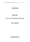
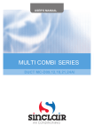
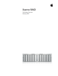
V1DI-09
V1DI-12
V1DI-18
V1DI-24
V1DI-30
V1DI-36
V1DI-45
V1DI-50
V1DI-60
DC Inverter Ducted Air-Conditioning Unit
Contents
Safety Considerations ............................................................................................ 1
User Notice .............................................................................................................. 3
I Displaying Part .................................................................................................. 4
1.1 LCD Display of Wired Controller ..........................................................................4
1.2 Instruction to LCD Display.....................................................................................5
Ⅱ Buttons ............................................................................................................. 6
2.1 Silk Screen of Buttons ............................................................................................6
2.2 Instruction to Function of Buttons ..........................................................................6
Ⅲ Installation of Wired Controller .................................................................... 7
Ⅳ Instruction to Operation ................................................................................ 8
4.1 On/Off ....................................................................................................................8
4.2 Mode Setting ..........................................................................................................8
4.3 Temperature Setting................................................................................................9
4.4 Fan Speed Setting ...................................................................................................9
4.5 Swing Control Function........................................................................................10
4.6 Timer Setting ........................................................................................................10
4.7 Air Exchange Setting* ........................................................................................11
4.8 Sleep Setting .........................................................................................................12
4.9 Turbo Function Setting .........................................................................................14
4.10 SAVE Function Setting ......................................................................................14
4.11 E-HEATER Setting* ........................................................................................16
4.12 Blow Function Setting ........................................................................................17
4.13 Quiet Function Setting........................................................................................18
4.14 Field Functions ...................................................................................................19
4.15 Other Functions ..................................................................................................19
Ⅴ Error Display ................................................................................................ 21
VI Remote control operation procedure(standard fitting) ............................. 24
VII Unit Function............................................................................................... 27
7.1 Setting of Double Indoor Room Sensors ..............................................................27
7.2 Checking of Outdoor Ambient Temperature ........................................................27
7.3 Fresh Air Control..................................................................................................27
VIII Installation Instructions............................................................................ 29
8.1 Instructions of Unit Installation ............................................................................29
8.2 Installation of Indoor Unit ....................................................................................33
8.3 Electrical Installation ............................................................................................41
IX Troubleshooting and Maintenance ............................................................. 45
Appendix ............................................................................................................... 47
Safety Considerations
Please read this manual carefully before use and operate correctly as instructed in the manual.
You are specially warned to note the two symbols below:
WARNING! : A symbol indicating that improper operation might cause human death or severe
injury.
WARNING! : A symbol indicating that improper operation might cause human property damage.
WARNING!
●
Children should be supervised to ensure that they do not play with the appliance.
●
This appliance is not intended for use by persons (including children) with reduced physical,
sensory or mental capabilities, or lack of experience and knowledge, unless they have been given
supervision or instruction concerning use of the appliance by a person responsible for their safety.
●
This unit shall be used in offices restaurants residences or similar places.
●
Please seek an authorized repair station for installation work. Improper installation might cause
water leakage, electric shock or fire.
●
Please install at a place strong enough to support the weight of air conditioner unit. If not , the air
conditioner unit might fall down and cause human injury or death.
●
To ensure proper drainage, the drainage pipe shall be correctly installed according to installation
instructions. Take proper measures for heat preservation to prevent condensing. Improper
installation of pipes might cause .leakage and wet the articles in the room.
●
Do not use or store flammable, explosive ,poisonous or other dangerous substances beside the air
conditioner.
●
In case of trouble (e. g .burnt smell) ,please immediately cut off the main power of air conditioner
unit .
●
Keep air flow to avoid shortage of oxygen in the room.
●
Never insert your finger or any objects into air outlet and inlet grill.
●
Never plug or unplug the power cable directly to start or stop the air conditioning unit.
●
Please take constant care to check if the mounting rack is damaged after long use.
●
Never modify the air conditioner. Please contact the dealer or professional installation workers for
repair or relocation of the air conditioner.
●
The appliance shall not be installed in the laundry.
●
Before installation, please check the power supply for compliance with the ratings on nameplate.
Check the power safety as well (Operating by professional)
●
Before use, please check and confirm if the cables , drainage pipes and pipelines are correctly
connected, hence to eliminate the risk of water leakage, refrigerant leakage, electric shock or fire.
●
Main power must be securely earthed to ensure effective grounding of air conditioner unit and avoid
the risk of electric shock. Please do not connect the earth cable to coal gas pipe, water pipe,
lightning rod or telephone line.
●
Once started , the air conditioner shall not be stopped at least after 5 minutes or longer, otherwise
1
the oil return to compressor may be affected.
●
Do not let the child to operate the air conditioner unit.
●
Do not operate the air conditioner unit with wet hands.
●
Please disconnect the main power before cleaning the air conditioner or replacing the air filter.
●
Please disconnect the main power if to put the air conditioner unit out of use for a long period.
●
Please do not expose the air conditioner unit directly under corrosive environment with water or
●
Please do not foot on or place any goods on air conditioner unit.
●
After electrical installation, the air conditioner unit shall be energized for electrical leakage
moisture.
test .(Operating by professional)
●
If the supply cord is damaged ,it must be replaced by the manufacturer or its service agent or a
similarly qualified person in order to avoid a hazard .
●
An all-pole disconnection switch having a contact separation of at least 3mm in all poles should be
●
The appliance shall be installed in accordance with national wiring regulations.
●
The temperature of refrigerant circuit will be high, please keep the interconnection cable away from
connected in fixed wiring.
the copper tube.
●
The power cord must be separated with the communication line.
2
User Notice
☆ Ensure unified power supply for each indoor unit.
☆ Never install wired controller in wet place or under sunlight directly.
☆ Shielding twisted pair line must be adopted as signal line or wiring (communication) of
wired controller once the unit is installed in the place where there is electromagnetic interference.
☆ Make sure communication line is connected into correct port to avoid communication
malfunction.
☆ Never knock, throw or frequently disassemble the wired controller.
☆ Never operate the wired controller with wet hand.
3
I
Displaying Part
Fig.1 Outline of wired controller
1.1
LCD Display of Wired Controller
Fig.2 LCD display
4
1.2 Instruction to LCD Display
Table 1
No.
Description
Instruction to Displaying Contents
1
Swing *
Swing function
2
Air *
Air exchange function
3
Sleep
Sleeping states
4
Running mode Each kind of running mode of indoor unit (auto mode)
5
Cooling
Cooling mode
6
Dry
Dry mode
7
Fan
Fan mode
8
Heating
Heating mode
9
Defrost
Defrosting state
10
Gate-control
card*
Gate control
11
Lock
Lock state
12
Shield
13
Turbo
14
Memory
15
Twinkle
Flicking when unit is on without operation of buttons
16
Save
Energy-saving state
17
Temperature
Ambient/setting temperature value
18
E-Heater*
E-HEATER display means electric-heater is available
19
Blow
Blow mark
20
Timer
Timer-displayed location
21
Quiet
Quiet state(two types: quiet and auto quiet)
Shielding state (buttons, temperature, on/off, mode or save is
shielded by long-distance monitoring
Turbo function state
Memory state (Indoor unit resumes original setting state after power
failure and then power recovery)
Notes: The functions with * are reserved for other models and are not applicable for the models
listed in this manual.
5
Ⅱ
Buttons
2.1
Silk Screen of Buttons
Fig. 3 Silk screen of buttons
2.2 Instruction to Function of Buttons
Table 2
No.
Description
1
Enter/cancel
2
▲
6
▼
① Running temperature setting of indoor unit, range :16~30°C
② Timer setting, range:0.5-24hr
③ Switchover between quiet/auto quiet
3
Fan
Setting of high/middle/low/auto fan speed
4
Mode
5
Function
7
Timer
Timer setting
8
On/off
Turn on/off indoor unit
4 Mode
and2 ▲
2 ▲and
6▼
Function of Button
① Function selection and canceling;
② Press it for 5s to enquiry the outdoor ambient temperature.
Setting of cooling/heating/fan/dry mode of indoor unit
Switchover among these functions of
air/sleep/turbo/save/e-heater/blow/quite
Press Mode and ▲for 5s under off state of the unit to enter/cancel
key memory function (If memory is set, indoor unit will resume
Memory function original setting state after power failure and then power recovery. If
not, indoor unit is defaulted to be off after power recovery. Memory
function is defaulted to be off before outgoing.)
Lock
Upon startup of the unit without malfunction or under off state of
the unit, press ▲ ▼ key at the same time for 5s in to lock state. In
this case, any other buttons won’t respond the press. Repress ▲ ▼
key for 5s to quit lock state.
6
Ⅲ
Installation of Wired Controller
Fig.4 Sketch for Installation of Wired Controller
No.
1
Socket’s base
Description box installed in
the wall
2
3
4
5
Soleplate of
controller
Screw M4X25
Front panel of
controller
Screw
ST2.2X6.5
Fig.4 Sketch for Installation of Wired Controller Pay attention to the following items during
installation of wired controller:
1. Cut off power supply of heavy-current wire embedded in mounting hole in the wall before
installation. It is prohibited to perform the whole procedure with electricity.
2. Pull out 4-core twisted pair line in mounting hole and then make it through the rectangle hole at the
back of controller’s soleplate.
3. Joint the controller’s soleplate on wall face and then fix it in mounting hole with screws M4X25.
4. Insert the 4-core twisted pair line through rectangle hole into controller’s slot and buckle the front
panel and soleplate of controller together.
5. At last, fix the controller’s front panel and soleplate with screws ST2.2X6.5.
Caution:
During connection of wirings, pay special attention to the following items to avoid interference of
electromagnetism to unit and even failure of it.
1. To ensure normal communication of the unit, signal line and wiring (communication) of wired
controller should be separate from power cord and indoor/outdoor connection lines. The distance
between them should be kept 20cm in min.
2. If the unit is installed at the place where there is interference of electromagnetism, signal line
and wiring (communication) of wired controller must be shielded by twisted pair lines.
7
Ⅳ
Instruction to Operation
4.1 On/Off
Press On/Off button to turn on the unit.
Repress this button to turn off the unit.
Note: The state shown in Fig.6 indicates off-state of the unit after energization.
The state shown in Fig.7 indicates on-state of the unit after energization.
Fig.6 Off state of the unit
4.2
Fig.7 On state of the unit
Mode Setting
Under on-state of the unit, press Mode button to switch the operation modes as the following
sequence:
Fig.8
8
4.3
Temperature Setting
Press ▲ or ▼button to increase or decrease of setting temperature under on-state of the unit. If
press either of them continuously, temperature will be increased or decreased by 1°C every 0.5s.
In Cooling, Dry, Fan and Heating mode, temperature setting range is 16°C~30°C.
In Auto mode, the setting temperature is un-adjustable.
As shown in Fig.9.
Fig.9
4.4
Fan Speed Setting
Press Fan button, fan speed of indoor unit will change as below:
As shown in Fig.10.
Fig.10
9
4.5
Swing Control Function
Under on-state of unit, press Function button till the unit enters swing control function and
then press Enter/cancel button to turn on “swing” control function.
During swing function, press Function button till the unit enters swing control function and
then press Enter/cancel button to cancel swing control function.
Swing control function setting is shown in Fig.11.
Fig.11
4.6
Timer Setting
Press Timer button to set timer off of the unit. Under off-state of the unit, press Timer button to
set timer on of the unit in the same way.
Timer on setting: Under off-state of the unit without timer setting, if Timer button is pressed,
LCD will display xx. Hour, with ON blinking. In this case, press▲ or ▼ button to adjust timer on and
then press Timer to confirm. If Mode button is pressed before pressing Timer button to confirm, timer
mode will be switched to timer off setting mode. In this case, LCD displays xx. Hour, with OFF
blinking. In this case, press▲ or ▼ button to adjust timer off and then press Timer to confirm. When
LCD displays :”xx. Hour on off”; xx. Hour means time of timer on, but time of timer off won’t be
displayed.
Timer off setting: Under on-state of the unit without timer setting, if Timer button is pressed,
LCD will display xx. Hour, with OFF blinking. In this case, press▲ or ▼ button to adjust timer on and
then press Timer to confirm. If Mode button is pressed before pressing Timer button to confirm, timer
10
mode will be switched to timer on setting mode. In this case, LCD displays xx. Hour, with ON blinking.
In this case, press▲ or ▼ button to adjust timer on and then press Timer button to confirm. When LCD
displays xx. Hour On Off, xx. Hour means time of timer off, but time of timer on won’t be displayed.
Cancel timer: After setting of timer, if Timer button is pressed, LCD won’t display xx. Hour
sothat timer setting is canceled.
Timer off setting under on-state of the unit is shown as Fig.12.
Fig.12 Timer setting under on state of the unit
Timer range: 0.5-24hr. Every press of▲ or ▼ button will make setting time increased or
decreased by 0.5hr.If press either of them continuously, setting time will automatically increase/
decrease by 0.5hr every 0.5s.
Note:
1. If both timer on and timer off are set in unit on interface, the wired controller only display time of
time off. If both of them are set in unit off-state, only time of timer on is displayed.
2. Timer on in unit on-state is timed from the time of unit off and timer off in unit off-state is timed from
the time of unit on.
4.7 Air Exchange Setting*
Turn on air Exchange function:
Under on-state of the unit, press Function button to go to the this function setting (Air mark
blinks).AIR 1 displayed at the ambient temperature-displayed location (888) is defaulted (the last type
of AIR will be displayed after adjustment).Press ▲ or ▼ button to adjust air type. Press Enter/Cancel
button to turn on/off air function. After turning on this function, the air mark shows.
There are 10 types of AIR, but only 1-2 types are for remote control. Refer to the following details:
11
1――The unit continuously runs for 60min, and fresh air valve runs for 6 min.
2――The unit continuously runs for 60min, and fresh air valve runs for 12 min.
3――The unit continuously runs for 60min, and fresh air valve runs for 18 min.
4――The unit continuously runs for 60min, and fresh air valve runs for 2 4 min.
5――The unit continuously runs for 60min, and fresh air valve runs for 30 min.
6――The unit continuously runs for 60min, and fresh air valve runs for 36 min.
7――The unit continuously runs for 60min, and fresh air valve runs for 42 min.
8――The unit continuously runs for 60min, and fresh air valve runs for 48 min.
9――The unit continuously runs for 60min, and fresh air valve runs for 54 min.
10――The unit continuously runs for 60min, and fresh air valve always runs.
Turn off air Exchange function: During Air function, press Function button to go to the Air
function. In this case, air mark is blinking, and then press Enter/cancel button to turn off this function.
Air mark will subsequently disappear.
Air Exchange setting is shown as in Fig.13:
Fig.13 Air exchange device
Note: In air exchange mode, press Function button or there is not any operation within 5s after the last
button operation, the system will be quit from air exchange setting and current energy-saving
data won’t be memorized.
4.8
Sleep Setting
Sleep on: Press Function button under on-state of the unit into sleep function and then press
Enter/cancel button to turn on sleeping function.
Sleep off: During sleep on-state, press Function button to go to the sleep function and then press
Enter/cancel button to turn off this function.
12
Sleep setting is shown as Fig.14:
Fig.14 Sleep setting
Sleep setting is clear after power failure and then power recovery. There is not sleep function in fan
and auto mode.
Note: In cooling and dry mode, if the unit with sleep function has run for 1 hour, the preset temperature
will be increased by 1°C and 1°C in another 1 hour. After that, the unit will run at this temperature.
In heating mode, if the unit with sleep function has run for 1 hour, the preset temperature will be
decreased by 1°C and 1°C in another 1 hour. After that, the unit will run at this temperature.
13
4.9
Turbo Function Setting
TURBO function: The unit at high fun speed can realize quick cooling or heating so that room
temperature can quickly approach setting temperature.
In cooling or heating mode, press Function button till the unit enters TURBO function and then
press Enter/cancel button to turn on TURBO function.
During TURBO function, press Function button till the unit enters TURBO function and then
press Enter/cancel button to cancel TURBO function.
TURBO function setting is shown in Fig.15 :
Fig.15 Turbo Function Setting
Note:
1. TURBO function will be turned off after power failure and then recovery. In dry, fan and auto
mode, TURBO function can not be set and TURBO mark won’t be displayed.
2. TURBO function will be automatically canceled after setting of quiet function.
4.10 SAVE Function Setting
Energy Saving Function: Energy saving can make the air conditioner runs in a smaller
temperature range by setting lower limited value of setting temperature in cooling or dry mode and
upper limited value in heating mode.
Energy Saving Setting for Cooling
Under on-state and in cooling or dry mode of the unit, press Function button into energy saving
function, with SAVE blinking .Press ▲ or ▼ button to adjust lower limited value of setting temperature
in cooing mode. After that press Enter/Cancel button to turn on energy saving function for cooling.
14
Energy Saving Setting for Heating
Under on state and in heating mode of the unit, press Function button into energy saving function,
with SAVE blinking. Press Mode button into energy saving function for heating and then press▲ or ▼
button to adjust upper limited value of setting temperature in heating mode. After that, press
Enter/Cancel button to turn on energy saving function for heating.
After energy saving function is turned on, press Function button into energy saving function and
press Enter/cancel to cancel this function.
The energy saving setting is shown in the Fig.16.
Fig.16 Energy Saving Setting
Note:
1. In Auto running mode with save function on, the unit will be forcibly quit Auto running Mode and
change to current operation mode, After setting of save, sleep function will be canceled.
2. In save mode, if Function button is pressed or there is not any operation within 5s after the last
button operation, the system will be quit from save function setting and current data won’t be
memorized.
3. After power failure and then recovery, save function setting will be memorized.
4. The lower limited value in cooling mode is 16°C and the upper limited value in heating mode is
30°C.
5. After save setting, if the setting temperature is out of the range in the mode, the limited value will
prevail.
15
4.11
E-HEATER Setting*
E-HEATER: In the heating mode, E-heater is allowed to be turned on for improvement of
efficiency. If heating mode is turned on by button operation, auxiliary electric heating function will be
automatically turned on.
Press Function button in heating mode to go to the auxiliary electric heating function, the
E-HEATER blinking, and press Enter/cancel button to turn on this function. In this case, the
E-HEATER will be displayed, which means E-heater is allowed to be turned on.
If auxiliary electric heating function is on, press Function button to confirm or press Enter/cancel
button to cancel. In this case, E-HEATER won’t be displayed, which means E-heater is prohibited to be
turned on.
The setting of this function is shown as Fig.17 below:
Fig.17 Auxiliary Electric Heating Function Setting
Note:
E-HEATER can not be set in cooling, dry and fan mode, E-HEATER mark won’t be displayed.
The setting is shown in Fig.17.
16
4.12 Blow Function Setting
BLOW function: After the unit is turned off, water in evaporator of indoor unit will be
automatically evaporated to avoid mildew.
In cooling and dry mode, press Function button till the unit enters BLOW function, with BLOW
blinking, and then press Enter/cancel button to turn on this function.
In BLOW mode, press Function button till the unit enters BLOW function and then press
Enter/cancel button to cancel this function.
BLOW function setting is shown in Fig.18
Fig.18 Blow function setting
Note:
1.After setting BLOW function, turn off the unit by pressing On/Off button on remote controller, indoor
fan will run at low fan speed for 10 min. (BLOW shows).Meanwhile, if BLOW function is canceled
indoor fan will be turned off directly.
2.There is not BLOW function in fan or heating mode.
17
4.13 Quiet Function Setting
Quiet function consists of two kinds: QUIET and AUTO QUIET.
Press Function button till the unit enters quiet function setting state, Quiet or Auto Quiet mark
blinks. In this case, press▲ or ▼ button to switch between Quiet and Auto Quiet and then press
Enter/cancel button to turn on this function.
In quiet mode, press Function button till the unit enters quiet function. In this case, Quiet or Auto
Quiet icon blinks and then press Enter/cancel button to cancel this function.
Quiet function setting is shown in Fig.19
Fig.19 Quiet function setting
Note:
1. During quiet function, fan speed is un-adjustable.
2. When turning on auto quiet function, the unit will enter quiet running state according to temperature
difference between room temperature and setting temperature. In this case, fan speed is adjustable. If
temperature difference between room temperature and setting temperature ≥ 4°C, fan will keep its
current speed; if 2°C≤temperature difference ≤3℃; fan speed will be reduced by one grade ,but if it is
at minimun. grade, it is un-adjustable.; if temperature difference ≤1°C, fan speed will be at minimun
grade
3. In auto quiet mode, fan speed can not be raised but reduced. If high fan speed is manually adjusted,
auto quiet mode will quit.
4. There is not auto quiet function in fan or dry mode. Quiet off is default after power failure and then
power recovery.
5. If quite function is set, turbo function will be canceled.
18
4.14 Field Functions
Under off-state of the unit, press Function and Timer buttons continuously for 5s to go to the
debugging menu. Press Mode button to adjust the setting items and ▲ or ▼ button to set the actual
value.
4.14.1 Ambient Temperature Sensor Setting
In field setting mode, press Mode button to adjust the temperature displayed location displaying 00,
and press ▲ or ▼ button to adjust setting state at timer displayed location. There are 3 types for
selection:
⑴ Indoor ambient temperature is that at return air inlet (01 is displayed at timer displayed
location)
⑵ Indoor ambient temperature is that at the place of screen (02 is displayed at timer displayed
location)
⑶ Return air inlet temperature sensor shall be selected for cooling, dry and fan modes and wired
controller temperature sensor (03 is displayed at timer displayed location) shall be selected for heating
and auto modes.
4.14.2 Three Grades of Speed for Indoor Fan
In field setting mode, press Mode button to adjust the temperature displayed location displaying 01
and press ▲ or ▼ button to adjust setting state at timer displayed location. There are 2 types for
selection:
⑴ 3 low grades (LCD displays 01)
⑵ 3 high grades (LCD displays 02)
Three low grades indicate high, medium and low grades and 3 high grades indicate super-high,
high and medium grades.
Press Enter/Cancel button to save the setting and quit after setting. If there is not any operation
within 20s after the system responds to the last button operation in this interface, the system will quit
this menu and display normal off-state; meanwhile, current setting won’t be saved.
4.15 Other Functions
4.15.1 Lock Function
Upon startup of the unit without malfunction or under off-state of the unit, press ▲ and ▼buttons
at the same time for 5s till the wired controller enters lock state. In this case, LCD displays:
. After
that, repress these two buttons at the same time for 5s to quit lock state.
Under lock state, any other buttons won’t give any response to the press.
4.15.2 Memory Function
Memory switchover: Under off-state of the unit, press Mode and ▲ buttons at the same time for 5s
to switch memory modes. During setting memory mode, Memory will be displayed. If this function is
not set, the unit will be under off state after power failure and then power recovery.
Memory recovery: If memory mode has been set for wired controller, the wired controller after
power failure will resume its original running state upon power recovery.
19
Note:
It will take about 5 seconds to save all the information, therefore, please do not cut down the power
at this time, or it may fails.
4.15.3 Enquiry of Outdoor Ambient Temperature
Under on or off state of the unit, press Enter/Cancel button for 5s, outdoor ambient temperature
will be displayed at temperature displaying location after a sound of click. This enquiry state will quit
by pressing any button. If there is not any operation for 20s, it will automatically quit.
Note:
1. This function will be shielded after energization of 12hr for some models of the units without
outdoor ambient sensors. Please refer to Instruction for details.
2. If malfunction of outdoor ambient sensor occurs, this function will be shielded in 12hr.
4.15.4 Selection of Centigrade and Fahrenheit
Under off state of the unit, press Mode and ▼ at the same time for 5s, the displayer panel will
switch between Centigrade and Fahrenheit.
4.15.5 Master/Slave Wired Controller Setting
Under the off status of the unit, press “Enter/cancel” and “Mode” at the same time for 5 seconds to
go to the master/slave wired controller setting interface, and then press ▲ or ▼ to make the adjustment.
In this case, only in the temperature display is there numbers displayed, 01 for the master wired
controller and 02 for the slave wired controller.
After that, press “Enter/cancel” to save the setting and quit this interface. If there is not any
operation in 20 seconds on this interface after the last button press, the system will quit automatically to
the normal off status without saving the current setting.
Note: If there is only one wired controller, it only can be set as the master; otherwise the unit won’t run
normally.
4.15.6 Gate-control Display Function *
If there is gate control system, the unit can run after plugging in card and stop after pulling out the
card.
If memory function is on, the unit after plugging out of card and then plugging in will run
according to the memory. If the card is not plugged in (or poor plugging), the mark
will show and
the unit will be turned off.
If memory function is off, the unit after plugging out the out will be turned off and the mark
will show. If re-plugging in the card, the mark will disappear and the unit enter will enter off state.
Note:
1. During long-distance monitoring, the unit on /off cannot be controlled by the card, but the mark
will also show after plugging in the card.
2. The unit cannot be controlled by button operation after plugging out the card.
20
Ⅴ
Error Display
If there is malfunction during running of the system, the wired controller will display error code at
temperature–displayed location. Once there is more than one malfunction, error codes will be displayed
circularly. If there are multiple circuit systems, the system number of failed system will be displayed
before the colon (not for single system).
If malfunction occurs, turn off the unit and contact nearest dealer for help.
As shown in Fig.20, it means high pressure protection of system 2 under unit on.
Fig.20
Table 3
Error code meaning:
Error code
Malfunction
E1
High pressure protection of compressor
E2
Indoor anti-freezing protection
E3
Low pressure protection of compressor
E4
High discharge temperature protection of compressor
E5
Compressor overload protection
E6
Communication malfunction
E9
Water overflow protection
F0
Indoor unit ambient sensor malfunction at air return opening
F1
Evaporator sensor malfunction
F2
Condenser sensor malfunction
F3
Outdoor unit ambient temperature sensor malfunction
F4
Discharge temperature sensor malfunction
F5
Ambient sensor malfunction on Displayer (or LED board)
21
Table 4 The LED Indicator Display on the Main Board of Outdoor Unit (09K/12K)
This table is applicable to the electric control box of the 09K and 12K C Series DC inverter air
conditioners. Some of the items are not malfunction; they mean the normal running status
wired
Outdoor unit
Outdoor unit
Outdoor unit
Running Status
controller
Red Lamp
Green Lamp
Yellow Lamp
Display
Compressor started
Flash once
Defrosting
Flash twice
Anti-freezing protection
Flash 3 times
E2
IPM protection
Flash 4 times
E5
Flash 5 times
E5
Flash 6 times
/
Flash 7 times
E4
Over-current protection
Heat
exchanger
protection
Discharge protection
overload
Displayed
Compressor overload protection
Flash 8 times
E5
Power protection
Flash 9 times
E5
Module overheating protection
Flash 10 times
E5
EEPROM reading error
Flash 11 times
E5
Low voltage protection
Flash 12 times
E5
High voltage protection
Flash 13 times
E5
PFC over-current protection
Unmatched indoor and outdoor
units
Limited frequency(current)
Flash 14 times
E5
Flash 16 times
/
Flash once
/
Flash twice
/
Limited frequency (overload)
Flash 3 times
/
Reduced frequency (anti-freezing)
Outdoor ambient temperature
sensor error
Outdoor pipe temperature sensor
error
Outdoor discharge temperature
sensor error
Up to the startup temperature
Limited frequency
(module temperature)
Flash 4 times
/
Flash 6 times
F3
Flash 5 times
F2
Flash 7 times
F4
Flash 8 times
Flash
11
times
Flash
13
times
/
Limited frequency (discharge)
Limited frequency (power)
Communication normal
Communication error
Indoor ambient temperature sensor
error
Indoor pipe temperature sensor
error
/
/
Flash
continuously
/
Black out
E6
F0
F1
22
Table 5 Definition of Malfunction Codes of DC Inverter General Outdoor Unit (V1.6)
This table is applicable to the electric control box of the other models of C-Series DC inverter air
conditioners.
Outdoor unit display of
dual 8 numeral tube
Malfunction Item
Indoor Unit
Display
DC busbar over voltage protection
PH
E5
Overheat protection of radiator
P8
E5
Current sensor malfunction
Pc
E5
Carbon fin sensor malfunction
P7
E5
Compressor current protection
P5
E5
Low voltage protection
PL
E5
Compressor startup failure
Lc
E5
PFC abnormality
Hc
E5
Compressor clogged
LE
E5
Drive resetting
P0
E5
The compressor motor in loss of synchronization
H7
E5
Missing phase, Speed discard
Ld
E5
Malfunction from driving part to main-control
communication
P6
E5
IPM module protection
H5
E5
Compressor over speed
LF
E5
Sensor connection protection
Pd
E5
Temperature drift protection
PE
E5
AC contactor protection
P9
E5
High-pressure protection
E1
E1
Low-pressure protection
E3
E3
Exhaust protection
E4
E4
Compressor overload protection
H3
E5
Communication malfunction (among indoor unit,
outdoor unit and wired controller)
E6
E6
Outdoor ambient temperature sensor malfunction
F3
F3
Coil pipe intermediate temperature sensor malfunction
of outdoor unit
F2
F2
Exhaust temperature sensor malfunction
F4
F4
Defrosting (non-malfunction)
08
defrost
Oil return (non-malfunction)
09
no display
Mismatch of indoor unit model
LP
no display
AC current protection (input side)
PA
E5
Driver board environment temperature sensor
malfunction
PF
E5
AC input voltage abnormality *
PP
E5
Electrification loop malfunction *
PU
E5
23
VI
Remote control operation procedure(standard fitting)
Names and Functions of Remote Controller Keys
Precautions:
z
This remote controller is a general-purpose remote controller, which can be used in various
types (functions) air conditioner. The keys not applicable to this air conditioner are not
explained here.
z
Ensure there is no obstacle between the remote controller and the signal receiving window
of the air conditioner.
z
The distance able to receive the signal of the remote controller can be as far as 8 meters.
z
Never drop or throw at will the remote controller.
z
Never let any liquid enter the remote controller. Avoid direct sunshine over the remote
controller. Do not place the remote controller in an extremely hot place.
Fig.21
Cooling Mode Operation
Connect the unit to power supply. Press the “ON/OFF” key. Press the “MODE” key to select
“Cooling” mode. Use the “Temperature” key to adjust the set temperature for the room. Refer to Fig.22.
Heating Mode Operation
Connect the unit to power supply. Press the “ON/OFF” key. Press the “MODE” key to select
“Heating” mode. Use the “Temperature” key to adjust the set temperature for the room. Refer to Fig.23.
24
Under the heating mode, the unit has the functions of preventing cold air supply and supplying
remaining heat. After the startup of the compressor, the indoor fan shall start operation when the
evaporator temperature is larger or equals 35℃ or after the unit has be started for 45 seconds, so as to
avoid supply of cold air shortly after the unit is started. After the stop of the compressor, the indoor fan
shall stop operation after supplying air for 120 seconds.
Swing
Fan Speed
Swing
Fan Speed
Swing
Swing
Auto
22
Auto
o
C
22
Model ON/OFF
Swing
o
C
Model ON/OFF
Fan Speed
Swing
Fan Speed
Swing
Auto
22
Swing
o
C
Auto
22
o
C
Model ON/OFF
Model ON/OFF
25
DRY (Dehumidifying) Mode Operations
Connect the unit to power supply. Press the “ON/OFF” key. Press the “MODE” key to select “DRY
(Dehumidifying)” mode. Use the “Temperature” key to adjust the set temperature for the room. Refer to
Fig.24.
Fan Mode Operation
Connect the unit to power supply. Press the “ON/OFF”key. Press the “MODE” key to select
“FAN” mode. The unit shall operate under “FAN” mode. Press the “FAN” key to select from high,
medium and low speed. Refer to Fig.25.
z
After batteries are installed,
the display shall display icons and
letter codes of all functions.
z
The life of batteries is
about 1 year.
z
Do not mix new and old
batteries or mix different types of
batteries in usage.
z
If the remote controller
shall not be used for a long time,
take out the batteries to avoid
2 Load two “AAA”
batteries
liquid leakage and any subsequent
failure.
(Accessories).
1 Open the cover.
2 Close the cover.
Fig.26 Replacing Batteries for Remote
Loading Batteries Into Remote Controller
Refer to Fig.26 for the methods and steps of installing batteries into the remote controller.
26
VII
7.1
Unit Function
Setting of Double Indoor Room Sensors
This series of ducted air-conditioning unit has two indoor room sensors. One is located at the air
intake of the indoor unit and the other one is located inside the wire controller.
User can select one from the two indoor room sensors on the basis of the engineering requirement.
(Refer to the section of wire controller instructions for detailed operation.)
Fig.27
7.2
Checking of Outdoor Ambient Temperature
The outdoor ambient temperature can be checked on the wire controller for the convenience of
users before going out. (Refer to the section of wire controller instructions for detailed operation.)
Fig.28
7.3
Fresh Air Control
11-levels control can be realized for the amount of fresh air taken in. The function not only
facilitates the health of users, but also controls the electricity consumption loss because of taking in
fresh air. This kind of control can be carried out through the wire controller. The function can set at any
time, goes into effect at any time, and features very simple operation. (Refer to the section of wire
controller instructions for detailed operation.)
27
Fig.29
The head of delivery of the condensate drainage pump can reach 1.1m, so that the engineering
installation is very convenient and prompt.
No Pump
V1DI-30
V1DI-60
V1DI-09
V1DI-12
Pump
V1DI-18
V1DI-24
V1DI-36
V1DI-45
V1DI-50
Fig.30
28
VIII
Installation Instructions
8.1 Instructions of Unit Installation
8.1.1
Profile Dimensions of Indoor Unit
Be suit for :
V1DI-09
V1DI-12
V1DI-18
Fig.31
Be suit for :
V1DI-24
V1DI-30
V1DI-36
V1DI-45
V1DI-50
Fig.33
29
Fig34
V1DI-60
Table 5
A
B
C
D
E
F
G
H
I
J
V1DI-09
840
561
635
790
880
665
738
125
203
250
V1DI-12
932
430
738
892
980
721
738
125
203
266
V1DI-18
932
430
738
892
980
721
738
125
203
266
V1DI-24
V1DI-30
1101
515
820
1159
1270
530
1002
160
235
268
1011
748
820
1115
1226
775
979
160
231
290
V1DI-50
1015
788
820
1115
1226
815
979
160
261
330
V1DI-60
1353
632
992
1150
192
343
1463
389
799
--
Item
Model
V1DI-36
V1DI-45
Model
Item
Connecting Pipe
Drainage
pipe(Diameter×wall
thickness)
Liquid
Gas
V1DI-09
1/4”
3/8”
φ20×1.2
V1DI-12
1/4”
3/8”
φ30×1.5
V1DI-18
1/4”
1/2”
φ30×1.5
3/8”
5/8”
φ20×1.2
3/8”
5/8”
φ20×1.2
V1DI-50
3/8”
5/8”
φ30×1.5
V1DI-60
3/8”
3/4”
φ30×1.5
V1DI-24
V1DI-30
V1DI-36
V1DI-45
30
Dimension Requirement of the Installation Space of Indoor Unit
Be suit for :
V1DI-09
V1DI-12
V1DI-18
Fig.34
Be suit for :
V1DI-24
V1DI-30
V1DI-36
V1DI-45
V1DI-50
Fig.35
Be suit for :
V1DI-60
Fig.36
Warning:The height of installation for the indoor unit should be 2.5m above.
31
8.1.2 Profile Dimensions of Outdoor Unit
Unit:mm
Fig. 37
Table 6
Item
Model
U1RS-09
U1RS-12
U1RS-18
U1RS-24
U1RS-30
U1RS-36
U1RT-36
U1RS-45
U1RT-45
U1RS-48
U1RT-50
U1RT-60
A
B
C
D
E
776
320
540
510
286
955
396
700
560
360
980
427
790
610
395
1107
440
1100
631
400
1107
440
1100
631
400
1085
427
1365
620
395
1085
427
1365
620
395
Fig.38
Unit Installation Instructions
Precautions on Installation of Outdoor Unit
To ensure the unit in proper function, selection of installation location must be in accordance with
following principles:
(1) Outdoor unit shall be installed so that the air discharged by outdoor unit will not return and that
sufficient space for repair shall be provided around the machine.
(2) The installation site must have good ventilation, so that the outdoor unit can take in and exhaust
enough air. Ensure that there is no obstacle for the air intake and exhaust of the outdoor unit. If there is
any obstacle blocking the air intake or exhaust, remove it.
(3) Place of installation shall be strong enough to support the weight of outdoor unit, and it shall be
able to insulate noise and prevent vibration. Ensure that the wind and noise from the unit will not affect
your neighbors.
(4) Avoid direct sunshine over the unit. It is better to set up a sun shield as the protection.
32
(5) Place of installation must be able to drain the rainwater and defrosting water.
(6) Place of installation must ensure the machine will not be buried under snow or subject to the
influence of rubbish or oil fog.
(7) The installation site must be at a place where the air exhaust outlet does not face strong wind.
8.2 Installation of Indoor Unit
8.2.1 Selection of Installation Site
(1) Ensure the top hanging piece has strong strength to withstand the weight of the unit.
(2) The drainage pipe has convenient flow of water.
(3) There is no obstacle blocking the air intake and exhaust outlet, so as to ensure sound air
circulation.
(4) The installation spaces required by the drawing must be ensured, so as to provide enough space
for the service and maintenance.
(5) The installation site must be far away from heat source, leakage of inflammable gas or smoke.
(6) The indoor unit is of ceiling mount (indoor unit is hidden inside the ceiling).
(7) The indoor and outdoor units, the power cable and the connecting electrical lines must be at
least 1 meter from any TV set or radio. This is to avoid image interference or noise of the TV set or
radio. (Even if the distance is 1 meter, noise can also exist if there is strong electric wave.)
8.2.2
Installation of Indoor Unit
(1) Insert a M10 expansion bolt into the hole. Drive a nail into the bolt. Refer to the profile dimensions
drawing of the indoor unit for the distance between the holes. Refer to Fig. 39 for the installation
of the expansion bolt.
Fig.39
(2) Install the hanger onto the indoor unit as Fig.40 shows.
(3) Install the indoor unit at the ceiling as Fig.41 shows.
Fig.40
Fig.41
Precautions for unfavorable installation:
1. The preparation of all pipes (connecting pipes and drainage pipes) and cables (connecting lines
of wire controller, indoor unit and outdoor unit) must be ready before the installation, so as to achieve
33
smooth installation.
2. Drill an opening on the ceiling. Maybe it is required to support the ceiling to ensure the evenness
of it and avoid the vibration of it. Consult with the user or a construction company for details.
3. In case the strength of ceiling is not enough, use angle iron sections to set up a beam support.
Place the unit at the beam and fix it.
8.2.3 Level Check of the Indoor Unit
After the indoor unit is installed, it is required to check the level of the whole unit. The unit must
be placed horizontally, but the condensate pipe shall be installed obliquely, so as to facilitate the
drainage of condensate.
Fig.42
8.2.4 Installation of Rectangular Air Pipe
Fig.43
Cautions:
The air supply pipe, the air intake pipe and the fresh air pipe must be covered with a layer of
thermal insulation, so as to avoid thermal leakage and condensation. Firstly apply liquid nail on the
pipes, then attach the thermal insulation cotton with a layer of tinfoil. Use the liquid nail cover to fix it.
Lastly use tinfoil adhesive tape to carefully seal the joints; other good thermal insulation materials can
also be used.
The air supply pipes and the air intake pipes shall be fixed to the prefabricated boards of the ceiling
by using iron supports. The joints of the pipes must be sealed by glue so as to avoid leakage.
The design and installation of air pipes must be in conformity with the relevant state engineering
criteria.
he edge of the air intake pipe must be at least 150mm away from the wall. The air intake must be
34
covered with filter.
Silencing and shock absorption shall be considered in the design and installation of the air pipes.
Additionally, the noise source must be far away from where people stay. The air intake shall not be
located above the place where users stay (offices and rest places, etc.).
8.2.5 Installation of Drainage Pipeline
(1) The Drainage Pipeline shall be installed with an inclining angel of 5~10°, so as to facilitate the
drainage of condensate. The joints of the Drainage Pipeline must be covered by thermal insulation
materials to avoid generation of exterior condensate. (As shown in Fig.44)
(2) A Drainage outlet is located at both the left and right sides of the indoor unit. After selecting
one Drainage outlet, the other outlet shall be blocked by rubber plug. Bundle the blocked outlet with
string to avoid leakage, and also use thermal insulation materials to wrap the blocked outlet.
(3) When shipped out from factory, both the Drainage outlets are blocked by rubber plugs.
(4) When connecting the drainage pipe with the unit, do not apply excessive force to the pipeline at
the side of the unit. The fixing position of the pipeline shall be near the unit.
(5) Purchase general-purpose hard PVC pipe locally to be used as the drainage pipeline. When
carrying out connection, place the end of the PVC pipeline into the drainage hole. Use flexible drainage
tube and tighten it with thread loop. Never use adhesive to connect the drainage hole and the flexible
drainage tube.
(6) When the laid drainage pipe is used for multiple units, the common pipe shall be about 100mm
lower than the drainage outlet of each set of unit. A pipe with thicker wall shall be used for such
purpose.
Fig.44 Thermal Insulation of Drainage Pipeline
Cautions: The joint of Drainage Pipeline must not have leakage.
8.2.6Testing of Drainage System
(1)After the electrical installation is completed, carry out the testing of the drainage system.
(2)During the test, check if the water correctly flows through the pipelines. Carefully observe the joints
to ensure that there is no leakage. If the unit is to be installed in a new house, carry out testing before
decorating the ceiling.
35
8.2.7 Selection of Connecting Pipe
The refrigerant is R410A, GWP=2020 ODP=0
Table 7
Item
Size of Fitting
Pipe(Inch)
Liquid
Gas
V1DI-09
U1RS-09
1/4”
3/8”
V1DI-12
U1RS-12
1/4”
3/8”
V1DI-18
U1RS-18
1/4”
1/2”
V1DI-24
U1RS-24
V1DI-30
U1RS-30
3/8”
5/8”
V1DI-36
U1RS-36
V1DI-36
U1RT-36
3/8”
5/8”
V1DI-45
U1RS-45
V1DI-45
U1RT-45
3/8”
5/8”
V1DI-50
U1RS-48
V1DI-50
U1RT-50
3/8”
5/8”
V1DI-60
U1RT-60
3/8”
3/4”
Model
Max.
Pipe
Length
(m)
Max. Height
Difference between
Indoor Unit and
Outdoor Unit m
Amount of
Additional
Refrigerant to be
Filled (For Extra
Length of Pipe)
20
15
30g/m
30
15
60g/m
50
30
60g/m
50
30
60 g/m
Note :
1. The standard pipe length is 5m. When the length (L) of the connecting pipe is less than or equals
7m, there is no need to add refrigerant. If the connecting pipe is longer than7m, it is required to add
refrigerant. In the above table, the amounts of refrigerant to be added for the models are listed for each
additional meter of pipe length.
2. The pipe wall thickness shall be 0.5-1.0 mm and the pipe wall shall be able to withstand the
pressure of 6.0 MPa.
3. The longer the connecting pipe, the lower the cooling effect and the heating effect..
8.2.8 Connection of Pipeline
1. Align the flared end of the copper pipe with the center of the thread joint. Manually tighten the
flared end nut.
2. Use torque spanner to tighten the flared end nut until the spanner clatters (Fig.45).
36
Fig.45
The following table describes the torques for tightening nuts of different pipe diameters.
Table 8
Pipe Diameter
Tightening Torque
1/4〞(Inch)
15-30 (N·m)
3/8〞(Inch)
35-40 (N·m)
5/8〞(Inch)
60-65 (N·m)
1/2〞(Inch)
45-50 (N·m)
3/4〞(Inch)
70-75 (N·m)
7/8〞(Inch)
80-85 (N·m)
3. The bending angle of the fitting pipe shall not be too large, and otherwise the pipe may break.
Please use a bender when bending the fitting pipes.
4. Use sponge to wrap the connecting pipe and joint, Then use plastic tape to bundle the sponge.
8.2.9 Air Purging
The purpose of the air purging is to get rid of moisture and air in the system, otherwise moisture
and air may cause ineffectiveness of the compressor which directly affects the cooling capacity.
1. Purging by Using Vacuum
1) Take out the nut cover of the inlet for refrigerant.
2) Connect the tube of the vacuum watch with the
vacuum pump, having the low-pressure end
linking to the inlet for refrigerant. As shown in
figure on right.
3) Starting the vacuum pump, when the indicator
turns to-1 bar, closing the low pressure handle
and stopping vacuum. Keep for 15 minutes,
ensuring the pressure of the vacuum watch remains.
4) Take out the valve cover of the gas valve together with the liquid valve.
37
Fig.46
5) Loosing the cord of liquid valve until the pressure rise to 0 bar.
6) Dismantle the tube from the cover of the inlet for refrigerant then, tighten the cover.
7) Loose the valve cord of the gas valve as well as the liquid valve entirely.
8) Tighten the valve cover of the gas valve and liquid valve so as to check whether leakage occurred.
2. Gap Leakage Check
Check if it leaks or not by applying soapsuds on every
joint and then inspect carefully. After the check, wipe them
off completely.
Cover the indoor unit joint with pipe insulation and four
plastic bands to prevent condensing at joints.
Fig.47
8.2.10 Liquid Pipe and Drain Pipe
If the outdoor unit is installed lower than the
indoor unit (See Fig.48)
1) A drain pipe should be above ground and the end of
the pipe does not dip into water. All pipes must be
restrained to the wall by saddles.
2) Taping pipes must be done from bottom to top.
3) All pipes are bound together by tape and restrained
to wall by saddles.
Fig.48
If the outdoor unit is installed higher than the indoor unit (See Fig.49)
1) Taping should be done from lower to the upper part.
2) All pipes are bound and taped together and also should be trapped to prevent water from returning
to the room (See Fig.50)
3) Restraint all pipes to the wall with saddles.
Fig.49
8.2.11 Installation of Protective Layer of Connecting Pipe
1. To avoid generation of condensate on the connecting pipe and avoid leakage, the big pipe and
the small pipe of the connecting pipe must be covered by thermal insulation materials, be bundled by
adhesive tape, and be isolated from air.
38
2. The joint connecting to the indoor unit must be wrapped by thermal insulation material. There
shall be no gap between the connecting pipe joint and the wall of the indoor unit. Refer to Fig.50.
Fig.50
Fig.51
Cautions: After the pipes are wrapped by protective materials, never bend the pipes to form very
small angle, and otherwise the pipes may crack or break.
3. Use adhesive tape to wrap the pipes:
(1) Use adhesive tape to bundle the connecting pipe and the cables together. To prevent condensate
from overflowing out from the drainage pipe, separate the drainage pipe firm the connecting pipe and
the cables.
(2)Use thermal insulation tape to wrap the pipes from the bottom of the outdoor unit until the upper
end of the pipe where the pipe enters the wall. When wrapping thermal insulation tape, the later circle
of tape must cover half of the front circle of tape (Refer to Fig.51).
(3)Wrapped pipe must be fixed to wall using pipe clamps.
Cautions:
(1)Do not wrap the protective tape too tight, and otherwise the efficiency of thermal insulation
may be decreased. Ensure that the condensate drainage flexible tube is separate from the bundled pipes.
(2)After the protective work is completed and the pipes are wrapped, use seal material to block
the hole in the wall, so as to prevent rain and wind from entering the room.
8.2.12 Position and Method of Installing Wire Controller
1. One end of the control wire of the wire controller is connected with main board of electric box
of indoor unit inside, it should be tightened by wire clamp, the other end should be connected with the
wire controller (installation sketch map as shown in below). The control wire be used for the indoor unit
and wire controller, which is special, the length is 8 meters, the material be adopted for the control wire
should be metallic substance. The wire controller could not be disassembled and the control wire be
used for the wire controller should not be changed by users optionally, the installation and maintenance
should be carried out by the professional personnel.
2. First select an installation position. According to the size of the control wire of the wire
controller, leave a recess or a embedded wire hole to bury the control wire.
3. If the control wire between the wire controller and the indoor unit is surface-mounted, use 1#
metallic pipe and make matching recess in the wall (refer to Fig.52; If concealed installation is adopted,
1# metallic pipe can be used (Refer to Fig.53).
4. No matter if surface mounting or concealed mounting is selected, it is required to drill 2 holes
(in the same level) which distance shall be the same as the distance (60mm) of installation holes in the
39
bottom plate of the wire controller. Then insert a wood plug into each hole. Fix the bottom plate of the
wire controller to the wall by using the two holes. Plug the control wire onto the control panel.
Lastly install the panel of the wire controller.
Caution:
During the installation of the bottom plate of the wire controller, pay attention to the direction of
the bottom plate. The plate’s side with two notches must be at the lower position, and otherwise the
panel of the wire controller cannot be correctly installed.
Fig.52 Surface mounting of Cable
Fig.53 Concealed mounting of Cable
Fig.54Sketch for Installation of Wired Controller
No.
1
2
3
4
5
Table 9
Name
Wall Surface
Bottom Plate of Wire Controller
Screw M4X10
Panel of Wire Controller
Screw ST2.2X6.5
Cautions:
1. The communication distance between the main board and the wire controller is 8 meters.
40
2. The wire controller shall not be installed in a place where there is water drop or large amount of
water vapor.
8.3 Electrical Installation
Cautions: Before installing the electrical equipment, please pay attention to the following
matterswhich have been specially pointed out by our designers:
(1)Check to see if the power supply used conforms to the rated power supply specified on the
nameplate.
(2)The capacity of the power supply must be large enough. The section area of fitting line in the
room shall be larger than 2.5mmP
(3)The lines must be installed by professional personnel.
An electricity leakage protection switch and an air switch with gap between electrode heads larger
than 3mm shall be installed in the fixed line.
1. Connection of signal wire
(1)Use wire stripper to strip the insulation layer (25mm long) from the end of the signal wire.
(2)Remove the screw at the terminal board of the air-conditioning unit.
(3)Use pliers to bend the end of the signal wire so that a loop matching the screw size is formed.
(4)Put the screw through the loop of the signal wire and fix the loop at the terminal board.
2. Connection of multiple twisted wires
(1)Use wire stripper to strip the insulation layer (10mm long) from the end of the multiple
twisted wires.
(2)Remove the screw at the terminal board of the air-conditioning unit.
(3)Use crimping pliers to connect a terminal (matching the size of the screw) at the end of the
multiple twisted wires.
(4)Put the screw through the terminal of the multiple twisted wires and fix the terminal at the
terminal board.
Warning:
If the power supply flexible line or the signal line of the equipment is damaged, only use special
flexible line to replace it.
1. Before connecting lines, read the voltages of the relevant parts on the nameplate. Then carry out
line connection according to the schematic diagram.
2. The air-conditioning unit shall have special power supply line which shall be equipped with
electricity leakage switch and air switch, so as to deal with overload conditions.
3. The air-conditioning unit must have grounding to avoid hazard owing to insulation failure.
4. All fitting lines must use crimp terminals or single wire. If multiple twisted wires are connected
to terminal board, arc may arise.
5. All line connections must conform to the schematic diagram of lines. Wrong connection may
cause abnormal operation or damage of the air-conditioning unit.
6. Do not let any cable contact the refrigerant pipe, the compressor and moving parts such as fan.
7. Do not change the internal line connections inside the air-conditioning unit. The manufacturer
shall not be liable for any loss or abnormal operation arising from wrong line connections.
8.3.1 Power Cable Connection:
1. Air-conditioning unit with single-phase power supply
41
(1)Remove the front-side panel of the outdoor unit.
(2)Pass the cable though rubber ring.
(3)Connect the power supply cable to the “L, N” terminals and the grounding screw on the metal
electric box.
(4)Use cable fastener to bundle and fix the cable.
2. Air-conditioning unit with 3-phase power supply
(1)Remove the front-side panel of the outdoor unit.
(2)Attach rubber ring to the cable-cross hole of the outdoor unit.
(3)Pass the cable through rubber ring.
(4)Connect the power cable to the terminal marked “L1,L2,L3 & N”. Connect earth wire to the
earthed terminal screw on the electric box.
(5)Use cable fastener to bundle and fix the cable.
Cautions:
Take great care when carrying out the following connections, so as to avoid malfunction of the
air-conditioning unit because of electromagnetic interference.
(1) The signal line of the wire controller must be separated from the power line and the connecting
line between the indoor unit and the outdoor unit.
(2) In case the unit is installed in a place vulnerable by electromagnetic interference, it is better to
use shielded cable or double-twisted cable as the signal line of the wire controller.
8.3.2 Connection of Signal Line of Wire Controller
1. Open the cover of the electric box of the indoor unit.
2. Pull the signal cable of the wire controller through the rubber ring.
3. Plug the signal line of the wire controller onto the 4-bit pin socket at the circuit board of the
indoor unit.
4. Use cable fastener to bundle and fix the signal cable of the wire controller.
8.3.3 Cable Connecting Diagram of Unit
The section area of cables selected by users must not be smaller than the specifications shown
diagram. The signal wire between indoor and outdoor unit shall be installed in the shielded bushing
Schematic Diagram of Unit Line Connection:
U1RS-09 +
U1RS-12 +
U1RS-18 +
U1RS-24 +
U1RS-30 +
U1RS-36 +
U1RS-45 +
U1RS-48 +
42
V1DI-09
V1DI-12
V1DI-18
V1DI-24
V1DI-30
V1DI-36
V1DI-45
V1DI-50
U1RS-09 + V1DI-09
1.Power cord 3×2.5 mm2(H07RN-F)
3. Communication Cords
U1RS-12 + V1DI-12
2.Power cord 3×1.0 mm2(H05VV-F)
U1RS-18 + V1DI-18
1.Power cord 3×4 mm2(H07RN-F)
2.Power cord 3×1.0 mm2(H05VV-F)
3. Communication Cords
U1RS-24 + V1DI-24
2.Power cord 3×1.5 mm2(H05VV-F)
1.Power cord 3×4 mm2(H07RN-F)
3. Communication Cords
U1RS-30 + V1DI-30
U1RS-36 + V1DI-36
U1RS-48 + V1DI-50
2.Power cord 3×1.5 mm2(H05VV-F)
U1RS-45 + V1DI-45
1.Power cord 3×6 mm2(H07RN-F)
3. Communication Cords
+
+
+
+
U1RT-36
U1RT-45
U1RT-50
U1RT-60
U1RT-36 + V1DI-36
U1RT-50 + V1DI-50
V1DI-36
V1DI-45
V1DI-50
V1DI-60
U1RT-45 + V1DI-45
U1RT-60 + V1DI-60
1.Power cord 5×4 mm2(H07RN-F)
3. Communication Cords
2.Power cord 3×1.5 mm2(H05VV-F)
The following table recommended by the model selection manual is about how to select the air
switch and power cable.
Warning! :
The section area of cables selected by users must not be smaller than the specifications shown in
the table below.
Table 10
Model
U1RS-09
U1RS-12
U1RS-18
U1RS-24
U1RS-30
U1RS-36
U1RS-45
U1RS-48
U1RT-36
U1RT-45
U1RT-50
U1RT-60
Power
Supply
220-240V~
50HZ
380-415V 3N~
50Hz
Capability of Air
Switch(A)
(Outdoor/Indoor)
16/6
16/6
20/6
20/10
32/10
32/10
32/10
32/10
20/10
20/10
20/10
20/10
43
Minimum Sectional Area
Of Earth Wire (mm2)
(Outdoor/Indoor)
2.5/1.0
2.5/1.0
4.0/1.0
4.0/1.5
6.0/1.5
6.0/1.5
6.0/1.5
6.0/1.5
4.0/1.5
4.0/1.5
4.0/1.5
4.0/1.5
Note: The parameters of the power cord listed above are only applicable to the BV single-core power
cord which is laid within the plastic bushing and used at 40℃, and those of the air switch are applicable
to the one which also is used at 40℃. If the actual installation conditions changes, please refer to the
instructions of the power cord and the air switch.
Table 11 Rated Parameters and Outline Dimensions of the Fuse
Unit
Code
Rated parameter
U1RS-09
46010408/
250V/15A
46010029
250V/3.15A
46010014/
250V/3.15A、
U1RS-12
U1RS-18
U1RS-24
U1RS-30
U1RS-36
U1RT-36
46010023
250V/30A
46010014/
250V/3.15A、
46010023
250V/30A
46010014/
250V/3.15A、
46010023
250V/30A
46010014/
46010023
46010014/
46010023
250V/3.15A
250V/3.15A
U1RS-45
46010014
250V/3.15A
U1RT-45
46010014
250V/3.15A
U1RS-48
46010014
250V/3.15A
U1RT-50
46010013
250V/5A
U1RT-60
46010013
250V/5A
All the indoor units
46010013
250V/5A
44
Dimensions
IX
Troubleshooting and Maintenance
If your air-conditioning unit suffers from abnormal operation or failure, please first check the
flowing points before repair:
Table 12
Failure
Possible Reasons
①The power supply is not connected.
The unit cannot be started.
②Electrical leakage of air-conditioning unit causes tripping of leakage
switch.
③The operating keys are locked.
④The control loop has failure.
The unit operates for a
while
and then stops.
①There is obstacle in front of the condenser.
②The control loop is abnormal.
③Cooling operation is selected when the outdoor ambient temperature
is above 43℃.
①The air filter is dirty or blocked.
②There is heat source or too many people inside the room.
③The door or window is open.
Poor cooling effect.
④There is obstacle at the air intake or outlet.
⑤The set temperature is too high thus cooling is hindered.
⑥There is refrigerant leakage.
⑦The performance of room temperature sensor becomes worse
①The air filter is dirty or blocked.
② The door or window is not firmly closed.
Poor heating effect
③The set room temperature is too low thus heating is hindered.
④There is refrigerant leakage.
⑤The outdoor ambient temperature is lower than -5℃.
⑥Control line is abnormal.
Note:
After carrying out the check of the above items and taking relevant measures to solve the
problems found but the air-conditioning unit still does not function well, please stop the operation of the
unit immediately and contact the local service agency designated by INVENTOR. Only ask professional
serviceman to check and repair the unit.
Routine Maintenance
1. Cleaning the Air Filter(Operating by the professional)
Do not disassemble the air filter when cleaning it. Otherwise failure may be caused
If the air-conditioning unit is used in an environment with much dust, you should clean the air
filter frequently (once every two weeks).
Cautions: You shall pay attention to the following matters when cleaning the
air-conditioning unit.
① Cut off all power supply before contacting the line connecting equipment.
② Only clean the air-conditioning unit after the unit is shut off and the power supply is
45
disconnected. Otherwise electrical shock or injury may be caused.
③ Do not use water to clean the air-conditioning unit. Otherwise there may be electrical shock.
④ Take care when cleaning the air-conditioning unit. Use a steady stepping stand.
2. Maintenance at the Beginning of Operating Season
Check the air inlet and outlet of the indoor and outdoor units to confirm there is no blockage.
Check to see if the grounding wire is in good condition;(Operating by the professional)
Check to see if the line connection is in good condition;(Operating by the professional)
Check if there is any word displaying on the LCD of the wire controller after connecting the unit to
power supply.
Note: If there is any abnormal condition, ask after sales to offer guidance.
3. Maintenance at the End of the Operational Season
When the weather is clear, operate the unit under fan mode for half a day, so as to dry the inside of
the unit.
If not to use the air-conditioning unit for a long time, please cut off the power supply. Now the
words on the LCD of the wire controller shall disappear.
46
Appendix
Air conditioner nominal working condition and working range:
Table 13
Test condition
Indoor side
Outdoor side
DB(℃)
WB(℃)
DB(℃)
WB(℃)
Nominal cooling
27
19
35
24
Nominal heating
20
--
7
6
Rated cooling
32
23
43
30
Low temp. cooling
21
15
18
--
Rated heating
27
--
24
18
Low temp. heating
20
--
-7
-8
Note:
1. The design of this unit conforms to the requirements of EN14511 standard.
2. The air volume is measured at the relevant standard external static pressure.
3. Cooling (heating) capacity stated above is measured under nominal working conditions
corresponding to standard external static pressure. The parameters are subject to change with the
improvement of products, in which case the values on nameplate shall prevail.
This product must not be disposed
together with the domestic waste. This
product has to be disposed at an
authorized place for recycling of
electrical and electronic appliances.
47
66129907235