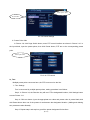
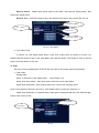
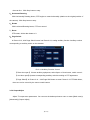
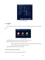
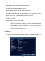
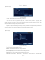
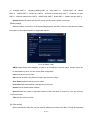
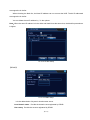
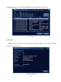
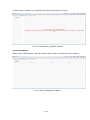
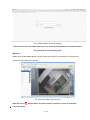
1
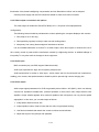
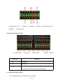
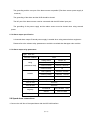
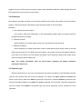
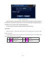
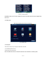
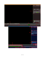
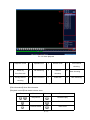
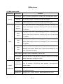
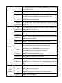
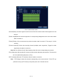
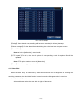
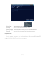
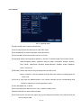
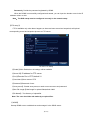
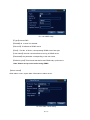
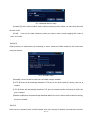
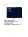
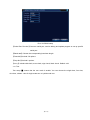
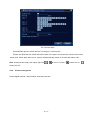
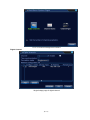
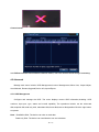
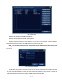
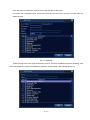
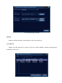
Professional NVR Instructions
Installation & Operation Manual
Warning:
Do not put heavy objects on the device.
Do not let any solid/liquid fall or penetrate into the device.
Please regularly brush the circuit boards, connectors, fans, chassis, etc.. Turn off the power and unplug it
before cleaning.
Do not disassemble/repair the device or have components replaced by yourself.
Environment:
Temperature between 0 ℃ ~ 40 ℃
is allowed to keep or use the device, sunlight exposure and heat
should be avoided.
Do not install the device under damp environment.
Do not expose the device under smoky & dusty environment.
Please avoid strong collision or accident dropping.
Please install the device horizontally in a stable place and avoid it from falling.
Please install the device in ventilated place.Keep the vent clean.
Can only be used within the rated input and output.
第 1页
Directory
Chapter1 Product Introduction................................................................................................................................. 4
1.1 Product overview.............................................................................................................................................4
1.2 Main functions.................................................................................................................................................4
Chapter 2 Unpacking check & cable connections..................................................................................................6
2.1 Unpacking check............................................................................................................................................. 6
2.2 HDD drive installation.................................................................................................................................... 6
2.3 Frame installation............................................................................................................................................7
2.4 Front panel.......................................................................................................................................................7
2.5 Rear panel......................................................................................................................................................10
2.6 Audio & video input and output connections............................................................................................... 12
2.6.1 Video input connections.....................................................................................................................12
2.6.2 Video output connctions and options.................................................................................................12
2.6.3 Audio input....................................................................................................................................... 12
2.6.4 Audio output..................................................................................................................................... 13
2.7 Alarm input & output connections...............................................................................................................13
2.7.1 Alarm input specification................................................................................................................. 15
2.7.2 Alarm output specification............................................................................................................... 15
2.7.3 Alarm output relay parameters......................................................................................................... 16
2.8 Speed dome connections.............................................................................................................................. 16
Chapter 3 Basic operations........................................................................................................................................17
3.1 Boot.............................................................................................................................................................. 17
3.2 Shut down.....................................................................................................................................................17
3.3 Login.............................................................................................................................................................18
3.4 Preview......................................................................................................................................................... 19
3.5 Desktop shortcut menu.................................................................................................................................20
3.5.1 Main menu........................................................................................................................................ 20
3.5.2 Playback............................................................................................................................................ 21
3.5.3 Record control...................................................................................................................................23
3.5.4 Alarm output..................................................................................................................................... 23
3.5.5 PTZ comtrol...................................................................................................................................... 24
3.5.6 Output adjust.....................................................................................................................................29
3.5.7 Shut down the system....................................................................................................................... 30
3.5.8 Full screen(Full screen Logout)..............................................................................................30
Chapter 4 Main menu................................................................................................................................................ 30
4.1 Main menu guide..........................................................................................................................................30
4.2 Record...........................................................................................................................................................32
4.2.1 Record Config...................................................................................................................................32
4.2.2 Playback............................................................................................................................................ 34
4.2.3 Backup.............................................................................................................................................. 34
4.3 Alarm............................................................................................................................................................ 35
4.3.1 Motion Detect................................................................................................................................... 35
4.3.2 Video Blind....................................................................................................................................... 37
4.3.3 Video Loss.........................................................................................................................................38
4.3.4 Alarm input....................................................................................................................................... 39
第 2页
4.3.5 Alarm output..................................................................................................................................... 39
4.3.6 Abnormal.......................................................................................................................................... 39
4.4 System Config.............................................................................................................................................. 40
4.4.1 General.............................................................................................................................................. 40
4.4.2 Network.............................................................................................................................................42
4.4.3 NetSevice.......................................................................................................................................... 43
4.4.4 Output mode......................................................................................................................................51
4.4.5 RS485.............................................................................................................................................. 52
4.4.6 Serial port config...............................................................................................................................53
4.4.7 Tour................................................................................................................................................... 53
4.4.8 Channel............................................................................................................................................. 54
4.5 Management Tools....................................................................................................................................... 58
4.5.1 HDD Manage.................................................................................................................................... 58
4.5.2 Account............................................................................................................................................. 59
4.5.3 Online user........................................................................................................................................ 62
4.5.4 Output adjust.....................................................................................................................................62
4.5.5 Auto maintain....................................................................................................................................63
4.5.6 Restore.............................................................................................................................................. 63
4.5.7 Upgrade.............................................................................................................................................63
4.5.8 Device Info.......................................................................................................................................64
4.5.9 Import/Output................................................................................................................................... 64
4.6 Info............................................................................................................................................................... 65
4.6.1 HDD info...........................................................................................................................................65
4.6.2 BPS....................................................................................................................................................65
4.6.3 Log.................................................................................................................................................... 66
4.6.4 Version.............................................................................................................................................. 67
4.7 Logout...........................................................................................................................................................67
Chapter 5 Basic operations for XM cloud................................................................................................................ 68
Chapter 6 FAQ and maintenance.............................................................................................................................. 73
6.1 FAQ............................................................................................................................................................... 73
6.2 Maintenance.................................................................................................................................................. 79
Appendix 1.Remote controller operation....................................................................................................................80
Appendix 2.Mouse operation......................................................................................................................................81
Appendix 3.HDD capacity calculation....................................................................................................................... 82
第 3页
Chapter 1 Production Introduction
1.1 Product overview
The NVR series , as excellent digital surveillance products,are specially designed for security and
surveillance field.Embedded LINUX operating system is introduced to ensure system stablility.With
advanced H.264 high profile video compression and its unique temporal filtering algorithm,it's quite easy
to
achieve
high-quality
image
along
with
synchronous
low
bit
rate
audio
&
video
surveillance.Additionally,it also introduces TCP/IP and other network technology,which equips it with
powerful network data transmission capacity as well as remote control capacity.
The NVR series can not only be used individually, but also form a powerful security and serveillance
network via getting access to the internet. What's more,strong network data transmission capacity and
remote control capacity can be realised with professional network video surveillance platform software.
The NVR series can be applied in bank, telecommunication, power, judicature, transportation,
intelligent community, factory, warehouse, resource, water conservancy facilities and many other fields.
1.2 Main functions
Real-time surveillance
·With spot interface, analog output port, VGA port and HDMI interface, to realize surveillance through
monitor or displayer.
Storage
·Non-working HDD dormancy processing which is convenient to radiate heat, reduce power and extend
the life-span
·With proprietary format , stored data can't be tampered, which ensures data security.
Compression
·Real-time compression via independent hardware which ensures the audio and video signal stablility &
synchronization.
Backup
·Through SATA interface and USB interface such as USB equipment, removable HDD and so on.
·Download file through net and store it in HDD.
第 4页
Playback
· Individual real-time video recording as well as searching, playback, network surveillance, recording
check, downloading and so on
·Multi-playback mode
·Zoom at arbitrary region
Net operating
·Realise long-distance real-time monitoring via net(mobile included).
·Long-distance PTZ control
·Long-distance video search and real-time playback
Alarm linkage
·Alarm links with video recording,tour ,message,buzzer,e-mail and FTP.
Communication interface
·With RS485 interface to achieve alarm input and PTZ control.
· With RS232 interface to realize mastering via extending keyboard connection, system maintenance
and upgrade with computer serial port connection as well as matrix control.
·With standard ethernet network interface to fulfill long-distance control.
Intelligent operating
·Mouse operation
·Fast and convenient copy and paste function for same settings.
第 5页
Chapter 2 Unpacking check & cable connections
2.1 Unpacking check
Please check the NVR the minute you receive it.
First, check whether there is obvious damage over the outside package. ( PS: Most accidental
strikes during transportation can be avoided with special protective marerials.)
Then, take out the device, remove the
protective plastic for DVR, check if there are obvious signs
of damage.
Finally, open the machine crust , check the connection between front panel data wire, power wire,
fan power and motherboard.
1.Front panel and rear panel
¨
The key function specifications of front panel and the interface specifications of real panel are
listed in the instructions.
¨
Please carefully check whether the front panel model matches with what you have ordered.
Please take care of the label sticked to the rear panel, which means a lot to our after sevice.
Model and serial number are needed when you need our sevice.
2.Check
After open the cover,you should check if it has obvious damage,also please check the connection
between front panel data wire, power wire and motherboard.
2.2 HDD installation
For first use, please install the HDD, the machine box can hold two hard drives (capacity unlimited).
第 6页
①disassemble the screw
④fix the screw of HDD
②disassemble the cover
⑤connect the data wire
⑦cover the machine
③fix the screw of HDD
⑥connect the power wire
⑧fix the cover
2.3 Shelf installation
The chassis specification for this product is standard 1u,which allows it to be installed in the
standard shelf.
Installation steps and attention items:
1、Make sure the temperature inside the room lower than 35℃ (95°f).
2、Keep 15 centimeters (6 inches) also around the device for air circulation.
3、Install from the bottom.
4、When multiple components are installed, please take precautions to avoid from overloading.
2.4
Front panel(please check the attached user manual)
2.5 Rear panel(please check the attached user manual)
2.6.1 Video input connections
No video input interface.
Insure vidicon signal stable and credible:
The vidicon should be installed in an appropriate place which is away from backlighting and has low
第 7页
illumination .Alas, better backlighting compensation and low illumination vidicon can be adopted.
Camera power supply and the DVR should be shared to make sure vidicon is stable.
2.6.2 Video output connections and options
The video output is divided into PAL/NTSC BNC(1.0VP-P,75Ω) and VGA output(selective
configuration).
The following issues should be paid attention to when replacing the computer displayer with monitor:
1、Don't keep it on for too long .
2、Demagnetizing regularly to keep it under normal working status.
3、Keep away from strong electromagnetic interference devices.
It is an unreliable alternative to choose TV as video output, which also requirs to minimize the use of
time ,strictly control of power and the interference caused by neighboring devices. In addition,leakage of
low quality TV may also result in damage to other equipment.
2.6.3 Audio input
BNC connection(only one BNC,support bidrectional talk).
Audio input impedance is high, which requires pickups active .
Audio transmission is similar to video input , which means the line should avoid from interference,
welding, poor contact, and special attention should be paid to prevent high current stringing into.
2.6.4 Audio output
Audio output signal parameters for DVR are generally above 200mv 1KΩ (BNC), which can directly
connect low impedance headphones, powered speakers or drive other video output devices with
amplifier. Output whistle appears when external speakers and microphone can not prevent spatial
segregation .In this case ,you can take steps as follows:
1、 Adopt better directional tone arm.
2、 Adjust speaker volume, keep it lower than the value of generated howling.
3、 Use fitment materials that absorb the sound to reduce sound reflection.
4、Adjust the layout of the pickups and speakers.
第 8页
2.7 Alarm input and output connections
Before connecting the device,please pay attention to follow situations:
*Note:T series have no alarm input/output functions.
1.Alarm input
A.
Alarm input is grounding alarm input.
B.
Alarm input requires grounding voltage signal.
C.
When the alarm is connected with two NVR or with NVR and other equipments, it should be
isolated by relay.
2.Alarm output
Alarm output for DVR can not be connected to heavy power load (no more than 1A).Relay damage from
excessive current should be avoided . Contactor isolation is required when using high-power load.
3.PTZ decoder connections
A.
The grounding of the PTZ decoder and NVR must be shared otherwise the common-mode
voltage will lead to the PTZ control failure. The shielded twisted pair is recommended.
B. Avoid the entrance of high voltage. Make sure the layout is reasonabe. Take precaution from the
thunder.
C.
In the outlying end, connect 120Ω resistance paralleled to reduce the inflection to insure the
signal quality.
D.
The 485 AB lines of NVR can not be connected with other 485 output equipments paralleled.
E.
The voltage between the AB lines of the decoder must be less than 5V.
4.Front equipment grounding note
Bad grounding can lead to chip burnout.
5.Alarm input unlimited
The NVR alarm output port is constant opening.
eight external alarm interface
第 9页
(1) alarm input 1,2,3,4
(6) ground
(2) ground
(3) RS232
(4) RS485
(5) alarm input 5,6,7,8
(7) alarm output
sixteen external alarm interface
①⑥⑧alarm input
②⑦ground
③alarm output
Parameter
⑤RS485
④RS232
Meaning
G
grounding
R,T
RS232 port
A,B
485 communication interface, which is connected with the
recording control equipment such as the decoder.
2.7.1 Alarm input specification
8 /16 channels alarm input. Alarm input type unlimited.
第 10页
The grounding and the com port of the alarm sensor are parallel (The alarm sensor power supply is
external) .
The grounding of the alarm and the NVR should be shared.
The NC port of the alarm sensor must be connected with the NVR alarm input port.
The grounding of the power supply and the alarm sensor must be shared when using external
power.
2.7.2 Alarm output specification
2 channels alarm output. External power supply is needed when using external alarm equipment.
Please refer to the relevant relay parameters to avoid the overload that damages main machine.
2.7.3 Alarm output relay parameters
Type:JRC-27F
Interface material
silver
Rating switch
30VDC 2A,
rating
maximal switch
125VA 160W
(resistance load)
maximal switch
250VAC, 220VDC
maximal switch
1A
Homo-polarity
1000VAC 1minute
Inhomo-polarity
1000VAC 1 minute
Interface and
1000VAC 1 minute
Homo-polarity
1500VAC
isolation
Surge voltage
Turn-on time
3ms max
Turn-off time
3ms max
longevity
mechanical
50×106 MIN(3Hz)
electric
200×103 MIN
-40~+70℃
Environment
2.8 Speed dome connections
1.Connect the 485 line of the speed dome with the NVR 485 interface.
第 11页
the 485 interface of eight external alarm
the 485 interface of sixteen external alarm
2.Connect the video line with the DVR video input.
3.Electrify the speed dome.
3 Basic operations
Note: Gray button indicates nonsupport.
3.1 Boot
Plug the power, open the rear panel power switch, power turns on, video recorder starts. Buzzer
beeps after booting .The default video output is multi-screen output mode. When start-up time is within
video setting time, the system will start timer recording automatically , the corresponding channel
recording indicator light turns on, system starts working.
Note:1. Make sure the input voltage corresponds to device power pull-bit switch.Turn on the power
switch after confirming.
2. Power supply demands: 220V±10% /50Hz.
第 12页
Suggest using the UPS to protect the power supply under allowable conditions, stable voltage value and
less interference power input are recommened.
3.2 Shut down
Soft-switching and hard switching can shut down the device.Soft switch, enter [main menu]> [shut down
system] , Select [shut down]; Hard switch, press the power switch on the rear panel.
Directions:
1、Auto resume after power failure
If the NVR is shut down abnormally, it can automatically backup video and resume previous
working status after re-starting.
2、Replace the HDD
Before replacing, the power supply switch in the real panel must be turned off.
3、Replace the battery
Before replacing, the setting information must be saved and the power supply switch in the real
panel must be turned off. The NVR uses button battery. The system time must be checked regularly.
If the time is not correct you must replace the battery, we recommend replacing the battery every
year and using the same battery type.
Note: The setting information must be saved before replacing the battery otherwise
information will be lost.
3.3 System Login
When the NVR boots up, the user must login and the system provides the corresponding functions
with the user purview.There are three user settings. The names are admin, guest and default and
these names need no password. Admin is the super user purview; guest and default’s permissions are
preview and video playback. User admin and guest’s password can be revised, while their permissions
can’t be revised; user default is the default login user whose permission can be revised but not its
password.
第 13页
Picture 3.1 System Login
Password protection: If the password is continuous wrong three times, the alarm will start. If
the password is continuous wrong five times, the account will be locked. (Through rebooting or
wait half an hour, the account will be unlocked automatically).
For your system security, please modify your password after first login.
3.4 Preview
After login normally,
preview screen will be seen. You can click right mouse to choose the switch
between the windows.
The system date, time and channel name are shown in each viewing window. The surveillance video
and the alarm status are shown in each window.
1
Recording status
3
Video loss
2
Motion detect
4
Camera lock
Table 3.1 Preview icon
第 14页
Pic 3.2 Preview interface
(1)
Channel name and status display,click
(2)
Screen switch
(4)
Pages flip up and down under
“channel” to pack up
(3)
Full screen display
non-16-channel mode
Play ull channel video/shut down full
(5)
Play/shut down full channel
(6)
channel video
Note:It’s main stream resolution under single window,and it’s sub-stream resolution under
multi-screen.
3.5 Desktop shortcut menu
Under preview mode you can right click mouse to get a desktop shortcut menu,as the picture 3.2
shows.The menu includes: main menu, record mode, playback, PTZ control, High Speed PTZ,
Alarm Output,Output adjust, Logout, full screen(leave full screen).
第 15页
Non full screen
full screen
Picture 3.3 Shortcut Menu
Note:When under non full screen, display”full screen”,and when under full screen display”leave
full screen”.
3.5.1 Main menu
Main menu includes various functions of the device.
Pic 3.4 Main menu
3.5.2 Playback
There are two ways for you to play the video files in the HDD
1.In the desktop shortcut menu
2.Main Menu>Record>playback
Note: The HDD which saves the video files must be set as read-write or read-only state.
第 16页
第 17页
Pic 3.5 Video playback
1
Playback control
2
Operation hint
3
Record mode
4
Time interval
choosing
5
Switch by
6
File searching
7
Channel
8
Date choosing
time,file mode
9
Storage device
choosing
10
File information
11
Listed files
12
choosing
【Listed files】Display files that accord with the searching criteria.
【File information】Show file information.
【Playback control】See details in below chart
Button
/
Function
Button
Function
Play/Pause
Backward play
Slow forward
Fast forward
Previous frame
Next frame
第 18页
Time searching
Previous file
Next file
Round play
Full screen
Stop
Edit
Table 3.2 Playback control key
Note: Frame by frame play should be under paused status.
【Operation hint】Show key function that cursor places.
Special functions:
Local zoom:When the system is in single-window full-screen playback mode, left-click your mouse
anywhere on the screen to zoom the selected area, double click to exit.
Note: When current resolution of the channel is over max resolution, a Red X will show when
playback the channel.
3.5.3 Record Control
Please check current channel status: “○” means it is not in recording status, “●” means it is in
recording status.
You can use desktop shortcut menu or click [Main menu]> [Record]> [Record Conf] to enter the
record control interface.
Pic 3.6 Record Mode
【Schedule】Record according to the configuration.
【 Manual 】 Whatever state the channel is in, select Manual button to record the corresponding
channel.
【Stop 】 Whatever state the channel is in, select Stop button to stop recording the corresponding
channel.
3.5.4 Alarm output
第 19页
Please check current channel status: “○” means it is not in alarming status, “●” means it is in
alarming status.
You can use desktop shortcut menu or click [Main menu]> [Alarm]> [Alarm output] to enter the
alarm output interface.
Pic 3.7 Alarm output
【Configuration】Alarm is on according to the configuration.
【 Manual 】 Whatever state the channel is in, select Manual button to output alarm signal through
corresponding channel.
【 Stop 】 Whatever state the channel is in, select Stop button to stop output alarm signal through
corresponding channel.
3.5.5
PTZ control
PTZ control,the digital channel need to link PTZ, the remote device should connect with PTZ
and with protocol correctly set also.
Control PTZ on the connected device, you can enter the interface through desktop shortcut menu.
Operation interface is as follows. The functions include: PTZ direction control, step, zoom, focus,
iris, preset operation, tour,pattern, border, assistant switch, light switch,autopan and so on.
Note1. Before operating,make sure decoder A(B)line connects with NVR A(B)line.
2. Click [Main menu] >[System] >[PTZ Config] to set the PTZ parameters.
3. The PTZ functions are decided by the PTZ protocols.
第 20页
Pic 3.8 PTZ setup
【 Speed 】 Set the PTZ rotation range. The higher the number is ,the faster the speed can get
to.Setting range: 1 ~ 8, Default:5
【Zoom】Click
/
button to adjust the zoom multiple.
【Focus】Click
/
button to adjust the focus .
【Iris】Click
/
button to adjust the iris.
【Hide】Current interface will be temporarily hidden after clicking.
【Direction control】Control the PTZ rotation. 8 directions control are supportive.(Only 4 directions of
front panel are supportive )
【High speed PTZ】Full-screen show channel image. Left press mouse and control PTZ to rotate
orientation. Left press mouse and then rotate the mouse to adjust the zoom multiple.
【Set】Enter the function config. menu.
【Page switch】Enter the function operation menu.
Special functions:
1、Preset
Set a location for the preset , PTZ automatically turns to the setting position
1)Preset config.
Set a location for the preset, procedure is as follows:
Step1: Click the Direction button to turn into preset position , click the Settings button to enter.
Step 2: Click the Preset button to input value in the preset box.
Step 3: Click Settings button, Set is complete , that is, preset point corresponds to preset
position.
Clear Preset:Input preset points, click Remove button, remove the preset.
第 21页
Preset point input
Preset button
Pic 3.9 Preset Settings
2)Preset Point Calls
In Picture 3.8, click Page Switch button, enter PTZ control interface as shown in Picture 3.10. In
the input blank, input the preset points, then click Preset button, PTZ turn to the corresponding preset
point.
Value input blank
Pic 3.10 PTZ control
2、Tour
Multiple preset points connected tour ,the PTZ run around on the line.
1)Tour Settings
Tour is connected by multiple preset points, setting procedure is as follows:
Step1: In Picture 3.8, the Direction key will turn PTZ to designated location ,click Settings button
to enter Picture 3.11.
Step 2: Click tour button ,input the appropriate tour value and preset value in preset blank,click
Add Preset button then one of the presets is set between the designated location. (Adding and deleting
tour presets are also allowed)
Step 3: Repeat step1 and step2 to get all the preset designated Cruise lines.
第 22页
Remove Preset : Please input preset value in the blank, click Remove Preset button, then
remove the preset points.
Remove Tour:Input the number of tour, click Remove tour button, then remove the tour set。
Preset Points Blank
Tour
Button
Time interval
Patrol number Blank
Pic 3.11 Tour setup
2)The Calls of Tour
In Picture 3.8, click Page Switch button, enter PTZ control menu as shown in Picture 3.10.
Please input the number of tour in the value blank, then click tour button, PTZ begins to work on the tour
patrol. Click Stop button to stop tour.
3、Scan
Set a tour route by operating the PTZ.PTZ also can work on the preset scan line repeatedly. 。
1)Scan setup
Setting steps:
Step1: In Picture 3.8, click Setup button ,enter Picture 3.12;
Step2: Click Scan button,then input proper value in the scan value blank;
Step3:Click Start button, enter Picture3.8,here you can set the following items:
Zoom,Focus,Aperture,Direction and so on. Click Setup button to go back to Picture 3.12
Step4: Click End button to complete setup. Scan value corresponds with the route.Click the right
button of the mouse to exit.
Scan value blank
Scan Button
第 23页
Pic 3.12 Scan Setup
2)Scan Calls
In Picture 3.8, click Page Switch button, then enter PTZ control menu as shown in Picture 3.10.
Please input the number of scan in the value blank , then click Scan button,PTZ begins to work on the
scan line . Click Stop button to stop.
4、Boundary Scan
In a horizontal line,set up a line,call scan,PZT repeat operation according to the route
1)Boundary Scan setup
Set a period of horizontal curve for PTZ search path,the steps are as follows:
Step1:In Picture 3.8, click Direction button to turn the PTZ to preset direction, then click Setup
button enter Picture 3.13, select the left boundary, return to Picture 3.8;
Step2:Please click direction arrows to adjust PTZ direction, click Setup button enter Picture3.13,
then select the right boundary ,return to Picture 3.8;
Step3: Setup complete, that is the position of left and right boundary
Note:when the left and right scan in one horizontal,the PTZ will cycle rotate from left scan along the
reverse direction to the right scan.
When the left and right scan not in the same horizontal ,the PTZ will regard the end of horizontal line
which connects to to the left as right scan,cycle rotate from left scan along the reverse direction to the
right scan.
Left/Right scan setting button
Line scan button border
Pic 3.13 Boundary Scan Setup
2)Boundary Scan Calls
In Picture 3.8, click Page Switch button, then enter PTZ control menu as shown in Picture 3.10.
Please input the number of scan in the value blank , then click Scan button,PTZ begins to work on
第 24页
the scan line . Click Stop button to stop.
5、Horizontal Rotating
Click Horizontally Rotating button, PTZ begins to rotate horizontally (relative to the original position of
the camera). Click Stop button to stop.
6、Rotate
Click horizontal Rotating button, PTZ turn around.
7、Reset
PTZ restart, all the data clears to 0.
8、Page Switch
In Picture 3.10, click Page Switch button into Picture3.14, setting auxiliary function. Auxiliary number
corresponding to auxiliary switch on the decoder.
Pic 3.14 Auxiliary Function Control
【Direct Aux open】 Choose auxiliary equipment, select Open or Close button, switch control;
【Aux Num open】Operate corresponding auxiliary switch according to PTZ agreement;
【Page Switch】In Picture 3.14,click Page Shift button to enter Picture 3.15 PTZ Main Menu ,
the menu can be control by the menu control buttons.
3.5.6 Output Adjust
Adjust TV output area parameters. You can use the desktop shortcut menu or enter [Main menu]>
[Advanced]> [Output Adjust].
第 25页
Pic 3.15 Output Adjust
3.5.7
Logout
Logout, shut down the system or reboot up. You can use the desktop shortcut menu or enter [main
menu].
Pic 3.16 Logout
【logout】Exit the menu. Need to re-login next time you enter the menu.
【Shut down】Exit the system. Shut down the power supply.
When pressing the shut down button, there is schedule hint. After three seconds, the
system is shut down. Cancel midway doesn’t help.
【Reboot】Exit the system. Reboot up the system.
3.5.8 Full screen(Full screen Logout)
Choose full screen or non full screen according to demans.
第 26页
4 Main menu
4.1 Main menu guide
Main menu
Sub menu
Record conf
Record
Playback
Backup
Function
Set the recording configuration, recording type, recording time section
Set recording search, recording play, video file storage
Detect backup device, format device, back the selective files
Set motion detect alarm channel,linkage parameters: defending time
Motion
section, alarm output, screen hint, recording, PTZ, tour, buzz, email and
detection
FTP upload.
Set video blind alarm channel,linkage parameters: defending time
Video
section, alarm output, screen hint, recording,PTZ, tour, buzz, email and
blind
FTP upload.
Set video loss alarm channel, linkage parameters: defending time
Video
Alarm
section, alarm output, screen hint, recording,PTZ, tour, buzz,email and
loss
FTP upload.
Set alarm input channel, equipment type, linkage parameters:
Alarm
defending time section, alarm output, screen hint,recording,PTZ, tour,
input
buzz, email and FTP upload.
Alarm output
Set alarm mode: configuration, manual, stop
Abnormality
No HDD, HDD error, HDD capacity not enough, network cut, IP Conflict,
handling
linkage parameters, screen hint or buzz.
Set system time, data format,date separator,time format,language,
General
HDD full operation, machine No, video standard, Auto logout,DST,
configuration
machine name.
System
configuration
Network
configuration
NetService
Set basic network parameters, DHCP and DNS parameters, network
high speed download.
PPPOE、NTP、Email、IP Filter、DDNS parameter and so on.
第 27页
Set channel title, preview hint icon state, transparency, cover area, time
GUI display
title, channel title fold.
RS485
Set protocol,address,baudrate,data bits,stop bits,parity.
Serial port
Set serial port function,baudrate,data bits,stop bits and parity.
settings
Tour
Channel
Management
HDD
management
Set patrol mode and interval time
Set channel mode, check channel status and configure the digital
channel, etc.
Set appointed HDD as read/write disk, read-only disk or redundant disk,
format disk, recover and so on
User
Modify user, team or password. Add user or team. Delete user or team
management
Break the connection with the already login user. Lock the account after
Online user
break until booting up again.
Output adjust
Management
Automatic
tools
maintenance
Adjust top deflate, bottom deflate, left deflate, right deflate.
Set automatic reboot system and automatic deleting files.
Restore setting items states:general,record conf,alarm
Restore
set,network,netservice,GUI display,account,RS232.
Upgrade
upgrade with external device(such as USB)
Device Info
device hardware configuration and message
Export the device's log or configuration to external device(like USB
Import/Export
flash disk);Input the configuration with external device(like USB flash
disk).
HDD info
Display HDD capability and recording time
System
BPS
Display code stream information
information
Log
Clear all log information according to the log video and time
Version
Display version information
第 28页
Shut down
Logout, shut down or reboot
4.2 Record
Operations corresponding to record, including: Record, Playback, Backup
4.2.1 Record Configuration
Set channel parameters. The system is set 24 hours consecutive recording in the first startup. You
can enter [Main Menu]> [Record> [Record Conf] to set.
Note:There is at least one read-write HDD for nomal record.(refer to chapter 4.5.1)
Picture 4.1 Record Conf
【 Channel 】 Choose the corresponding channel number. Choose the all option to set the entire
channels.
【Redundancy】Choose the redundancy function to double backup the file,which means writing the
video files in two HDDs. When you do the double backup, make sure that there are two HDDs
installed. One is read-write disk and the other is redundant disk. (refer to 4.5.1)
【Length】Set the time length of each video file. 60 minutes is default value.
【Record Control】Set video state: schedule, manual or stop.
Configuration:Record according to the set video type (common, detection and alarm)and
time section.
Manual: Whatever state the channel is in, the corresponding channel recording is under
第 29页
common mode when manual button is selected.
Stop: Whatever state the channel is in, the corresponding channel recording stops when
stop button is selected.
【 Period 】 Set the time section of common recording, The recording will start only among the set
range.
【Record type】Set recording type: regular, detection or alarm.
Regular:Record according to the set time section. The video file type is “R”.
Detect:Within the set time section,trigger the motion detect, video blind,video analysis or
video loss signal. When above alarm is set as opening recording, the recording
detection state is on. The video file type is M.
Alarm: Within the set time section ,trigger the external alarm signal. When above alarm is
set as opening recording, the recording detection state is on. The video file type is A.
Note: Refer to chapter 4.3 to set corresponding alarm function.
4.2.2 Playback
Refer to chapter 3.5.2.
4.2.3 Backup
You can backup the video files to external storage through setup.
Note : The accommodate storage must be installed before the file backup. If the backup is
terminated, the
already backup can playback individually.
第 30页
Picture 4.2
detect storage device
【Detect】Detect the storage connected with the NVR such as HDD or universal disk.
【 Backup 】 Click backup button and the dialog box pops up. You can choose the backup file
according to the type, channel and time.
Picture 4.3 Backup
Remove:Clear the file information.
Add:Show information satisfying the set file attributes.
Backup format:Configurate the backup file format, you can choose
Start/pause:After choosing the files and the backup format ,click the play button to start the
backup or click the pause button to stop.
Note:During backup you can exit to carry out other functions.
【Burning】The file will be burned synchronously after clicking.
【Erase】Choose the file you want to delete and click erasure to delete it.
【Stop】Stop the backup.
4.3 Alarm Function
Alarm functions include: motion detect,video blind, video loss, alarm input and alarm output,
abnormality.
第 31页
4.3.1 Motion Detect
When system detects the motion signal that reaches the set sensitivity, the motion detect alarm is on
and the linkage function is turned on.
Note: Both the NVR and the connected device need to enable Motion Detect function,then it works.
Advanced button works the same with right of the mouse.
Pic 4.4 motion detect
【Channel】Choose the set motion detect channel.
【Enable】■ means that the motion detect function is on, select enable button to config..
【Period】Trigger the motion detect signal in the set time section. You can set according to week or
set uniformly. Each day is divided into four time sections.■ means the set valid.
第 32页
Pic 4.5 set the time section
【Interval】Only one alarm signal is turned on even there are several motion detect signals in the set
interval.
【Alarm output】Start the external equipment of corresponding linkage alarm when the motion detect
alarm is turned on.
【Delay】Delay a few moments and stop when the alarm state is turned off. The range is 10~300
seconds.
【 Record channel 】 Choose the recording channel (multiple option supportive). Trigger the video
signal when the alarm is turned on.
Note:Set in the [Record Conf]. Start detecting video files in the corresponding time section.
【Tour】■ means that the selective channel is single window alternate patrol preview. The interval is
set in the [Main Menu]>[System] > [Tour].
【PTZ Activation】Set the PTZ activation when the alarm is turned on.
Note :PTZ linkage is about the channel corresponding to the remote device. To link PTZ, go
[Shortcut menu]->[PTZ control] to set preset point, tour & interval time etc.
第 33页
Pic 4.6 PTZ linkage
【Delay】When alarm is over,recording will last some seconds(10~300sec),then stop.
【Show message】Pop the alarm information dialog box in the local host computer screen.
【Send EMAIL】■ means sending an email to user when the alarm is turned on.
Note:Set in the [NetService] to send emails.
【 FTP upload 】 To tick it, the video & picture of corresponding record & snapshot files will be
uploaded.
Note:FTP upload needs to be set in [Netservice]
【Buzz】When alarm happens, device will come out with buzz.
4.3.2 Video Blind
When the video image is influenced by the environment such as bad brightness or reaching the
sensitivity parameter, the video blind function is turned on and the linkage function is turned on.
Note:Both the NVR and the connected device need to enable video blind function ,then it works.
Advanced button works the same with the right of the mouse.
第 34页
Pic 4.7 video blind
Set method: refer to chapter 4.3.1. Motion detect.
4.3.3 Video Loss
When the equipment can not obtain the channel video signal, the video loss alarm is turned on and
the linkage function is turned on.
Note:Both the NVR and the connected device need to enable this function ,then it works.
Advanced button works the same with the right of the mouse.
第 35页
Pic 4.8 Video loss
Set method: refer to chapter 4.3.1. Motion detect
4.3.4 Alarm input
When the equipment obtains the external alarm signal, the alarm function is turned on.
Note: Advanced button works the same with the right of the mouse.
Pic 4.9 Alarm input
Set method: refer to chapter 4.3.1. Motion detect
4.3.5 Alarm output
Refer to chapter 3.5.4.
4.3.6 Abnormal
Analysing and inspecting current software and hardware: When some abnormal events happen,the
device will make a relative answer such as show message ,buzzer and so on.
第 36页
Pic 4.10 Abnormal handing
【Event Type】
【Enable】
【Show message】
【Buzzer】
selecting abnormity you need
Select it to make sure abnormal function works.
Automatically alarm cue dialog box comes out of the main screen.
Device will have one long nosie like di when alarm is turned on.
4.4 System Config.
Set the system parameters such as:General,Network, Net service,GUI display,PTZ
configuration/RS485 ,RS232,Tour and channer management。
第 37页
4.4.1 General
Pic 4.11 general setup
【System time】Set the system data and time.
【Date format】Choose the data format: YMD, MDY, DMY.
【Date Separator】Choose list separator of the data format.
【Time Format】Choose time format: 24-hour or 12-hour.
【Language】Support 29 language at present:S- Chinese,T-Chinese,English,Farsi,Finnish,French,
Greek,Hungarian, Italian, Japanese, German, polish, Portuguese, Russian, Spanish,
Thai, Turkish, Vietnamese, Romania, Brazil,Indonesia, Swedish, Arabic, Bulgarian,
Czech, Hebrew, etc.
【HDD full】Choose stop record: Stop recording when the HDD is full.
Choose overwrite: Cover the earliest recording files and continue recording when the
HDD is full.
【 DVR No. 】 Only when the address button in the remote controller and the corresponding NVR
number is matched, the remote operation is valid.
【Video Standard】PAL or NTSC.
【Auto Logout】Set the latency time in 0-60. 0 means no latency time.
【Machine Name】Can set the device's name.
【DST】Choose the summer time option and pop the dialog box as follows. Set start time and end
time by week or date.
第 38页
Pic 4.12 DST (week)
Pic 4.13 DST (date)
4.4.2 Network setup
Pic 4.14 Network setup
【Net Card】You can choose cable network card.
第 39页
【DHCP Enable】Obtain IP address automatically(not suggested)
Note:DHCP server is pre-installed.
【IP address】Set the IP address. Default: 192.168.1.10.
【Subnet mask】Set the subnet mask code. Default: 255.255.255.0.
【Gateway】Set the default gateway. Default: 192.168.1.1.
【DNS setup】Domain Name Server. It translates the domain name into IP address. The IP address
is offered by network provider. The address must be set and reboot then it works.
【TCP port】Default: 34567.
【HTTP port】Default: 80.
【HS Download】:To download at a high speed.
【Transfer Policy】There are three strategies: self-adaption, image quality precedence and fluency
precedence. The code stream will adjust according to the setup. Self-adaption is the
tradeoff between the image quality precedence and fluency precedence. Fluency
precedence and self-adaption are valid only when the sub-stream is turned on.
Otherwise image quality precedence is valid.
4.4.3 NetService
Choose the network service option and click the set button to configure the advanced network
functions or double click the service button to configure the parameters.
第 40页
Pic 4.15
Netservice
【PPPoE setup】
Pic 4.16 PPPOE
Enable:Reverse■ means selected,setting is effective.
Input the user name and password that ISP ( Internet service provider ) provides. After
saving ,reboot up your system. Then the NVR will build a network connection based on PPPoE. After
that,the IP address will change into dynamic IP address.
Operation:After PPPoE dialing successfully ,check the IP address in the [IP address] and obtain the
current IP address. Then use this IP address to visit the NVR through user client.
【NTP setup】
Pic 4.17 NTP setup
The NTP server must be installed in the PC.
Enable:Reverse■means selected,setting is effective.
Host computer IP:Input the IP address which installs NTP server.
Port:Default: 123. You can set the port according to NTP server.
Time zone:London GMT+0
Berlin GMT +1
Cairo GMT +2
第 41页
Moscow GMT +3
New Delhi GMT
+5
Bangkok GMT +7
GMT-10
Alaska GMT-9
Hongkong Beijing GMT +8
Pacific time GMT-8
Tokyo GMT +9
Sydney GMT +10
American mountain time GMT-7
GMT-6 American eastern time GMT-5 Atlantic time GMT-4
Hawaii
American mid time
Brazil GMT-3 Atlantic mid time GMT-2.
Update Period:The same with the NTP server check interval. Default: 10minutes.
【EMAIL setup】
When the alarm is turned on or the alarm linkage photos are taken, send an email about the alarm
information or the snapshot photos to appointed address.
Pic 4.18 EMAIL setup
SMTP server:Email server address. It could be an IP address or domain name. Domain name can
be translated only when it is the correct DNS configuration.
Port:Email server port number.
SSL:Decide whether using Secure Socket Layer protocol to login.
User Name:Applied email server user name.
Password:Input the password corresponding to the user.
Sender:Set the email sender address.
Receiver:Send the email to appointed receivers when the alarm is turned on. You can set three
receivers at most.
Title:You can set as you wish.
【IP Filter setup】
When choosing the white list, only the listed IP address can connect the NVR. The 64 IP addressed
第 42页
are supportive in the list.
When choosing the black list, the listed IP address can not connect the NVR. The 64 IP addressed
are supportive in the list.
You can delete the set IP address by √ in the options.
Note:When the same IP address is in the white and black list at the same time, the black list precedence
is higher.
Pic 4.19 IP filter setup
【DDNS】
Pic 4.20 DDNS setup
It is the abbreviation of dynamic domain name server.
Local domain name:Provide the domain name registered by DDNS.
User name:Provide the account registered by DDNS.
第 43页
Password:Provide the password registered by DDNS.
When the DDNS is successfully configured and started, you can input the domain name in the IE
address column to visit.
Note:The DNS setup must be configured correctly in the network setup.
【FTP setup】
FTP is available only when alarm happens,or alarm activates record and snapshot,it will upload
corresponding record and snapshot pictures to FTP server.
Pic 4.21 FTP setup
【Enable】Click Enable,then all settings will be available
【Server IP】IP address for FTP server
【Port】Domain Port of FTP,default 21
【User Name】User name of FTP
【Password】Password of user
【Anonymous】
:Enable anonymous,no need to set user name and password.
【Max File Length】Max length for upload files,default 128M
【Dir Name】:The directory of upload file.
Note: The user should be with authority to upload files.
【ARSP】
Startup DDNS server to add devices and manage it in the DDNS server
第 44页
Pic 4.22 ARSP setup
【Type】choose DNS
【Enable】■
means it is selected.
【Sever IP】IP address of DDNS server
【Port】: Port No. of device, corresponding DDNS server hear port.
【User name】the user name that device can log in DDNS server
【Password】the password corresponding to the user name.
【Refresh cycle】Time interval that device and DDNS stay synchronous.
Note: Please set up server before using DDNS.
【Alarm center】
When alarm occurs, report alarm information to alarm server.
Pic 4.23 Alarm center setup
第 45页
【Protocol type】GENERAL
【Enable】To tick it means enable.Settings are effective after enbling.
【Server IP】IP address of Alarm Server
【Port】Device Port No.
【Alarm Report】Tick it means to report alarm information to server.
【Log Report】Tick it, means to report log to server.
【Wireless Config】
ADSL through 3G net card,use CMS to visit and configure the device.
Pic 4.24
Wireless setup
【Enable】To tick it means enable.Settings are effective after enbling.
【Type】Dial type,default AUTO
【Wireless AP】3G access point
【Dial Number】3G Dial Number
【User Name】User name of 3G
【Password】Password of dial user
【IP Address】IP address,got from dialing.
【Mobile Monitor Setup】
To visit the device via mobile,please make a router mapping of this port and use mobile software to
monitor and operate it with protocol.
第 46页
Pic 4.25Mobile Monitor Setup
【Enable】To tick it means enable .Open mobile monitoring function,select it to make sure abnormal
function works
【Port】
It’s a port of mobile monitoring which you need to make a router mapping first if want to
visit it via mobile.
【UPNP】
UPNP protocol is to realise auto port forwarding on router, make sure UPNP enabled on the router when
using this function.
Pic 4.26 UPNP setup
【Enable】Choose Enable to make sure all UPNP settings available
【HTTP】Route will automatically distribute HTTP port for the device,while IE viewing, this port is
needed.
【TCP】Router will automatically distribute TCP port for the device,while monitoring via CMS, this
port is needed.
【Mobile Port】Router will automatically distribute Mobile Port for the device,while mobile monitoring,
this port is needed.
【WIFI】
NVR connect to wireless router via WIFI module, then visit it through IP address, but make sure the NVR
第 47页
has connected with WIFI modern first.
Pic 4.27 WIFI setup
【Search】:Click【search】to search all the available wireless device in current range.
【enable】:To tick it means enable.Settings are effective after enbling.
【auto obtain IP address】
:Tick it to enable, device will automatically obtain a WIFI IP.
【SSID】:Wireless LAN name, automatically match with the wireless device connected.
【Password】:Wireless network password of router;
【IP address】: Set the IP address, default is 192.168.1.12
【subnet mask】:Set subnet mask, default is 255.255.255.0
【gateway】
:Set gateway, default is 192.168.1.1
【RTSP】
To realise surveillance via cross-browser (Safari, Firefox, Google chrome ) and VLC software. This
function is only for monitor but can not control the device.
Pic 4.28 RTSP setup
【Enable】:■ means enable,Settings are effective after enbling.
【Port】:The default port is 554
第 48页
【Cloud】
【Enable】■ means enable,user can enter http://xmeye.net to login with serial number.
Pic 4.29 cloud
4.4.4 GUI Display
Configure the parameters of video output signal.
Local preview mode include:time display, channel title, record status, alarm status, anti-jitter,
transparency and resolution.
Pic 4.30 GUI display
【Time Display】■ means enable .Display the system data and time in the surveillance window.
【Channel title】■ means enable .Display the system channel number in the surveillance window.
【Record Status】Not supported.
【Alarm Status】■ means enable .Display the system alarm status in the surveillance window.
第 49页
【Transparency】Choose the background image transparency. The range is 128~255.
【Resolution】Set display resolution.
4.4.5 RS485
4.31 R485
【Protocol】Choose corresponding protocol for the model( for example: DaHua);
【Address】Set corresponding address, default is 1;
【Baud rate】Choose corresponding bard rate, default is 115200;
【Data bits】Include 5-8 options,default is 8;
【Stop bits】Include 2 options, default is 1;
【Parity】Include odd check, even check, sign check, blank check. Default: void.
4.4.6 RS232
第 50页
Pic 4.32 RS232 setup
【Serial Port Function】Common serial port ,used to debug and update program or set up specific
serial port.
【Baud rate】Choose the corresponding baud rate length.
【Data bits】Include 5-8 options.
【Stop bits】Include 2 options.
【Parity】Include odd check, even check, sign check, blank check. Default: void.
4.4.7 Tour
Tour setup. g means that the tour mode is enable. You can choose the single-view, four-view,
nine-view ,sixteen -view of single mode tour or hybrid mode tour.
第 51页
Pic 4.33 tour setup
【Interval】Set the tour switch interval. The range is 5-120 seconds.
【Alarm tour】Set the tour switch interval for alarm, the range is 5-120 seconds, choose return when
alarm ends. When alarm links to tour, system will automatically switch to six-view after alarm ends.
Note:Under preview mode, click upper right icon
/
means turn off).
4.4.8
Channel management
Include digital channel, channel status, and channel mode
第 52页
to turn on / off tour(
means turn on,
Pic 4.34 channel management interface
Digital channel:
Single linkage page of digital channel
第 53页
Multi-linkage page of Digital channel
Pic 4.35 digital channel interface
【Channel】Select channel number.
【Enable】■ means enable,Settings are effective after enbling.
【Time Synchronization】■ means enable ,which means channel syncs with device.
【Connection Mode】Single connection and multi-connection, multi-connection can connect to several
devices, device will be displayed one by one, tour interval can be set, no less than 10s;
【Delete】Select the device, click delete will do.
【Add】Click add ,the following interface will be seen.
Pic 4.36 remote channel configure page
第 54页
【Configure Name】The device has a default configure name, user can revise it if necessary;
【Device Type】3 types: IPC、DVR、HVR,user can choose what they need, default is IPC;
【Protocol】Default is NETIP, ONVIF is optional.
【Remote channel】User can input remote channel number for the device connected remotely.
【Stream】Main stream and sub-stream.Default is main stream.
【Port】Default is 34567
【User name】Default is admin
Note: Click the search button, the following devices will be displayed, the user can select
whatever device to connect based on their needs.
Pic 4.37 Device list
Channel Status:
When the device has digital channel, all digital channel status can be displayed, including maximum
resolution, current resolution, and connection status.
When all channels are connected nomally,you can see as below:
第 55页
When the channel is added to device but not enable, you will see as below:
Note:
when under multi-screen,sub-stream will be displayed,when under single screen, main stream
will be displayed.
when the current resolution is over the max resolution that the channel supports, then a red “X”
will be shown on the preview image, for example: Under full digital channel mode, Max resolution
of channel 3 is D1, if it was connected to a device with resolution over D1 ( such as 960H), you will
see below pic:
第 56页
Channel mode:
Note:Different models have different channel modes, user can shift the mode freely if necessary.
4.5 Advanced
Manage tools menu include: HDD Management,Account Management,Online User, Output Adjust,
Auto Maintain, Restore,Upgrade,Device Info,Import/Export.
4.5.1 HDD Management
Configure and manage the HDD. The menu displays current HDD information,including: HDD
numbers, input port, type, status and overall capability. The operations include: set the write-read
disk,snapshot disk,read-only disk, redundant disk,format disk,recover disk,partition.Click the right button
to operate.
Note:Read/Write Disk: The device can write or read data.
Read-only Disk: The device can read data but can not write data.
第 57页
Redundant Disk: Double backup the video files in the write-read disk.
Pic 4.38 HDD management
4.5.2 Account
Manage the user purview.
Note:1. The following user and user group names, etc. The character length is 8 bytes at most. The
blank ahead or behind the character string is invalid.The middle blank in the character string is valid.
Legal characters include: letter, number, underline, subtraction sign and dot, other characters are
not allowed.
2. There is no limit in user and user group number. You can add or delete the user group. The
factory setups include: user\admin. You can set the groups as you wish. User can appoint the
purview in the group.
3. The user management include: group/ user. The group and user name can not be the same. Each
user must and can only belong to one group.
第 58页
Pic 4.39 Account
【Modify User】Modify the existed user attribute.
【Modify Group】Modify the existed group attribute.
【Modify Password】Modify the user password. You can set 1-6 bit password. The blank ahead or
behind the char string is invalid. The middle blank in the char string is valid.
Note:The user who possess the user control purview can modify his/her own or other users
password .
Pic 4.40 modify password
【Add user】Add a user in the group and set the user purview. Enter the menu interface and input
the user name and password. Choose the group and choose whether to copy the user. Copying the
user means that the account can be used by multiple users at the same time.
第 59页
Once the group is chosen,the user purview is the subclass of the group.
For better user management,we recommend that the common user’s purview is lower than the
advanced user.
Pic 4.41 add user
【Add Group】Add a user group and set the purview. There are 33 different purviews,including: shut
down the equipment, real time surveillance, playback, record setting, video backup and so on.
第 60页
Pic 4.42 add group
【Delete User】Delete the current user. Choose the user and delete it.
【Delete Group】Delete the current group. Choose the group and delete it.
Pic 4.43 delete group
4.5.3 Online user
To check the information of network user connected with local device, also can tick the selected user
to break up connection,(click √ in the box),then the user will be frozen after connection stops, and will
not log in until device reboots.
Pic 4.44 online user
第 61页
4.5.4 Output adjust
Refer to chapter 3.5.7 .
4.5.5 Auto Maintain
The user can set the time to automatically reboot and delete.
Pic 4.45 auto maintain
4.5.6 Restore
The system restore to the default . You can restore the items according to the menu blow.
Pic 4.46 restore
Note: Under digital mode, no decoding setting included.
4.5.7 Upgrade
第 62页
Pic 4.47 upgrade
【Where to upgrade】Choose USB interface.
【Upgrade file】Choose the file you want to upgrade.
4.5.8 Device Info
Provide device interface info which can be set according to customers, to facilitate better understanding
and use.
Pic 4.48 device info
4.5.9
Import / Export
Users can export the log info and the configure file to external devices (such as USB), or you can import
configure file from external devices to settings, which greatly brings convenience to customers.
第 63页
Pic 4.49 import/export interface
4.6 Info
Display the HDD information, includs HDD info, BPS, log,version info.
4.6.1 HDD info
Display the HDD status,which contains: HDD type, overall capability, remaining capacity,status,
recording time and so on.
第 64页
Pic 4.50 HDD Info
Tips:○ means that the HDD is normal. X means that the HDD is broken-down.- means that there is
no HDD installed.When user needs to change the damaged HDD, NVR must be shut down first before
taking out all the damaged HDD,then a new one can be installed.
* behind serial number means the current working disk such as 1*. If the corresponding disk is
damaged, the information will show “?”.
Different models have different HDD numbers.
4.6.2 BPS
Real-time display channel image stream(Kb/S)and HDD capability (MB/H), which is shown in
waveform diagram.
Pic 4.51 BPS
4.6.3 Log
To search for log information base on the search mode setup.
Log information includes: system operation, configuration operation, data management, alarm
event, recording operation, account management, file management and so on. Set the time section ,and
click the search button. The log information will display in a list. (one page has128 items) Press Page up
第 65页
or Page down button to search and press delete button to clear all the log information.
Pic 4.52 log
4.6.4 Version
Display the basic information such as hardware information, software version, issue date, serial
number , NAT status and so on.
Pic 4.53 version info
第 66页
4.7 Shut down system
Refer to chapter 3.5.8.
5 Basic operations for XM cloud
5.1 Cloud technology surveillance
Cloud technology, which uses the serial number to get access to the device, not only enables the
device one step on net but also greatly brings convenience for customers to better monitor via wide area
network.
*Note: Device that supports cloud technology should be in the WAN( Wide Area Network )firstly.
Ø
Check the connection status of cloud technology
Connect device to WAN first, then enter【Main menu】>【Info】>【Version】to check whether the device
successfully connect to the cloud server or not.
第 67页
Connect failure interface
Connected interface
Pic 5.1 cloud technology server connection status
Ø
Log in cloud server
Enter http://xmeye.net to see below log.There are two ways to login: by user and by device, user
can log in freely based on their needs.
*Note: To log in by user, user needs to register at the first time.
Pic 5.2 Cloud login interface
Ø
Log in by user
第 68页
Customer logs in with their own registered user name and password, as below:
Pic 5.3 cloud technology operation interface
Device management:
Mainly used for adding device, click add to add a serial number for the device to be monitored.
Pic 5.4 device management interface
第 69页
Pic 5.5 add interface at device manage
Note:in pic 5.5, the user name means the user name of monitored device, password means
the password of corresponding user.
My Device
Mainly show all the added devices, click a device name which is successfully connected to the
server can get access to the monitor.
Pic 5.6 monitor page - log in by user
Note:the icon of
Ø
means offline, the device doesn’t connect to server successfully.
Log in by device
第 70页
Pic 5.7 log in by device interface
Input the serial number of device and the verify code to monitor and control the device directly.
Pic: 5.8 monitor page - log in by device
第 71页
6 FAQ and maintenance
6.1 FAQ
When the problems you come across are not listed, please contact the local service or call the HQ
service. We are willing to provide professional service.
1、
The NVR can not boot up normally.
Possible reasons are as follows:
2、
1
The power supply is not correct.
2
Switch power supply line is not in good connection.
3
Switch power supply is damaged.
4
The program updating is wrong.
5
The HDD is damaged or the HDD lines are broken.
6
The front panel is damaged.
7
The main board of the NVR is damaged.
The NVR reboots automatically or stops working after boot up a few minutes.
Possible reasons are as follows:
3、
1
The input voltage is not stable or too low.
2
The HDD is damaged or the HDD lines are broken.
3
The power of the switch power supply is too low.
4
Frontal video signal is not stable.
5
Bad heat radiator or too much dust or bad running circumstance for the NVR.
6
The hardware of the NVR is damaged.
System can not detect HDD.
Possible reasons are as follows:
1
The HDD power supply line is not connected.
2
The cables of the HDD are damaged.
3
The HDD is damaged.
4
The SATA port of main board is damaged.
第 72页
4、
There are no video outputs in single channel, multiple channels and all channels.
Possible reasons are as follows:
5、
1
The program is not matched. Please update the program.
2
Front-end device is not connected.
3
There is no video input signal or the signal is too weak.
4
The channel protection or the screen protection is set.
5
The hardware of the NVR is damaged.
Can not find the video files in local playback mode.
Possible reasons are as follows:
6、
1
The data line of the HDD is damaged.
2
The HDD is damaged.
3
Update program different from the origin program files.
4
The video files to look up are covered.
5
The recording is not on.
The local video is a mess.
Possible reasons are as follows:
1
Program data read errors, stream is small, mosaic under full screen playback mode,
usually back to normal after rebooting.
7、
2
HDD data cable and the HDD jumper error.
3
The HDD is damaged.
4
The hardware of the NVR is damaged.
There is no audio signal in the surveillance window.
Possible reasons are as follows:
8、
1
It is not an active tone arm.
2
It is not an active sound box.
3
The audio lines are damaged.
4
The hardware of the NVR is damaged.
There is audio signal in the surveillance window but no audio signal in the playback
status.
Possible reasons are as follows:
第 73页
1
Setting issues: the audio option is not chosen.
2
The according channel is not connected with the video,when the imageis blue screen, the
playback will be intermittent.
9、
The display time is wrong.
Possible reasons are as follows:
10、
1
Setting is wrong.
2
The battery is in bad connection or the voltage is too low.
3
The oscillation is damaged.
The NVR can not control the PTZ.
Possible reasons are as follows:
1
There is something wrong with the frontal PTZ.
2
The setting, connection or the installation of the PTZ decoder is not correct.
3
The connections are not correct.
4
The PTZ setting of the NVR is not correct.
5
The protocols of the PTZ decoder and the NVR are not matched.
6
The address of the PTZ decoder and the NVR are not matched.
7
When multiple decoders are connected, the far port of the PTZ decoder line A(B) must
connect a 120 W
resistance to reduce the reflection otherwise the PTZ control is not
stable.
8
11、
The distance is too far.
The motion detect is not working,
Possible reasons are as follows:
12、
1
The time section set is not correct.
2
The motion detect function in the front is not on .
3
Limited by some hardware edition.
Cannot login via web or CMS.
Possible reasons are as follows:
1
The system is windows 98 or win me. We recommend updating windows to 2000sp4 or
higher Version or installing the software for low edition.
2
ActiveX is hold back.
第 74页
13、
3
The version is not exceeded dx8.1. Update the display card driver.
4
Network connection failure.
5
Network setting issues.
6
Invalid password or user name.
7
The CMS doesn’t match with the NVR program version.
No image or mosaic under network preview screen and video file playback mode.
Possible reasons are as follows:
14、
1
Poor network patency.
2
The user machine is resource limited.
3
Choose the play-in-team mode in the network setup of NVR,which is not recommended.
4
The region shelter or channel protection is set.
5
The user has no surveillance purview.
6
The real-time image of the HDD recording machine itself is not clear.
Network connection is not stable.
Possible reasons are as follows:
15、
1
Network is not stable.
2
IP address is conflicted.
3
MAC address is conflicted.
4
The net card of the NVR or the computer is bad.
There is something wrong with the USB backup or USB burn.
Possible reasons are as follows:
16、
1
The rewritable machine and the HDD are sharing the same data lines.
2
The data is too much. Please stop recording and backup.
3
The data exceeds the backup storage,which is easy to go wrong.
4
The backup equipment is not compatible.
5
The backup equipment is damaged.
The keyboard can not control the NVR.
Possible reasons are as follows:
1
The serial port of the NVR is not set correctly.
2
The address is not correct.
第 75页
3
When multiple transformers are connected, the power supply is not large enough. Please
give each transformer individual power supply.
4
17、
The transmission distance is too far.
Alarm can not be recessional.
Possible reasons are as follows:
18、
1
The setting of the alarm is not correct.
2
The alarm output is turned on manually.
3
The input machine is damaged or the connections are not correct.
4
There are some problems for specific program edition, Please update the program.
Alarm is not working.
Possible reasons are as follows:
19、
1
The setting of the alarm is not correct.
2
The connection of the alarm is not correct.
3
The alarm input signal is not correct.
4
A alarm is connected with two loops synchronously.
The remote controller is not working,
Possible reasons are as follows:
20、
1
The remote control address is not correct.
2
The remote control distance is too far or the angle is too large.
3
The battery is used up.
4
The remote controller or the front panel of the recording machine is damaged.
The storage time is not enough.
Possible reasons are as follows:
1
Front vidicon quality is bad. The lens is too dirty. The vidicon is in backlighting installed or
Iris lens is not well adjusted.All of the above can lead to large stream.
21、
2
The HDD capability is not enough.
3
The HDD is damaged.
The downloading files can not play.
Possible reasons are as follows:
1
There is no media player.
第 76页
2
There is no DX8.1 software or higher edition.
3
There is no DivX503Bundle.exe file to play AVI video files.
4
The DivX503Bundle.exe and ffdshow-2004 1012 .exe files must be installed in the windows
xp system.
22、
Can not remember the advanced password or network code in the local menu operation.
Please contact the local service or call the HQ service. We will guide you to solve the problems
according to your machine type and program version .
23、
Can not see the preview picture through digital channel.
Possible reasons are as follows:
1 Did not add device
2 The device of corresponding channel was not enable.
3 The device of corresponding channel was not selected.
4 The selected device did not connect to video sources.
5 The channel title of selected remote device does not exist.
6 Stream for remote channel was set sub-stream.
7 User name & password not matched
8 Directly input IP address or port No. incorrectly when adding device.
9. The resolution of added device is too large to display by monitor.
24、
Click search but cannot search out any of the device.
Possible reasons are as follows:
1 There is no other device existing in the Local area network
2 The subnet mask setting incorrectly.
25、
The time shows on digital channel is not the same with local client:
Enable the time synchronous function for digital channel.
26、
When shifting devices ,picture will be frozen under multi-connection mode.
Few seconds are needed for pictures to come out from digital channel. While switching ,to show
a new screen, a few seconds are needed to buffer.
第 77页
6.2 Maintenance
1
Dirt falling onto circuit will cause a short circuit in damp environment , which has bad
influence on DVR or can even damage it.Therefore,to ensure the DVR work steadily in
long-term, please regularly brush printed circuit boards, connectors, fans, machine box and
so on.
2
Please keep the project well grounding to prevent from video or audio signal interfered and
the NVR from static or inductive electricity.
3
Do not pull out the video signal line or RS-232 port or RS-485 port with the power on.
4
Do not use the TV as local video output port(VOUT) of NVR,which will damage the video
output circuit easily.
5
Do not turn off the switch directly. Please use the turn-off function in the menu or press the
turn-off button in the panel (3 seconds or longer) to protect the HDD.
6
Please keep the NVR away from heat resource.
7
Please keep the NVR ventilated for better heat radiator.
Please check and maintain the system regularly.
第 78页
Appendix 1.Remote controller operation
Serial
Name
Function
number
Multi-window
1
Enter multi-screen preview interface
button
Numeric
2
Code input/number input/channel switch
button
3
【Esc】
Go back to front page
Direction
4
Direction keys and Enter key
button
Playback
5
Basic operations under video playback.
control
Record
6
Enter record control menu.
control
Remote
7
Input the number of NVR to control it
Address
8
Auxiliary key
Assistant function
第 79页
Appendix 2.Mouse operation
*Take right hand mouse operation as an example.
The mouse in USB connection is supported.
Operation
Function
Double click one item in the file list to playback the video
Double left
Double click the playback video to zoom in or out the screen
click
Double click the channel to make it full screen display
double click again to resume the multi-window display
Left click
Choose the according function in the menu
Pop desktop shortcut menu in preview status
Right click
Current shortcut menu in the menu
Press middle
wheel
Add or subtract number in the number setting
Switch the items in the combo box
Page up or down in the list
Move mouse
Choose the widget or move the item in the widget
Set the motion detect area
Drag mouse
Set the cover area
第 80页
Appendix 3.HDD capability calculation
Make sure the HDD is installed inside the NVR for the first time. Pay attention to the IDE HDD lines
connection.
1、 HDD capability
There is no capacity limit for single HDD., you can choose hard drives over 10G . For better
stability,we recommend 120G~250G.
2、 Overall capability option
The HDD capability formula is:
Overall capability(M)=channel number*time(hour)*capability per hour(M/hour)
The recording time formula is:
overall capability(M)
Recording time(hour)=
Capability per hour(M/hour)*channel number
The
NVR
introduces
H.264
compression
technology,which
has
a
large
dynamic
range.Therefore the HDD capability calculation is based on the stream statistics,with which to
estimate file size each channel creats per hour.
For example:
For a piece of 500G HDD, to record CIF real-time,it keeps recording for about 25 days.HDD spaces
per channel is 200M/H,when 4 channels real time CIF at 24hours recording uninterrupted,it can last 26
days(500G/(200M/H*24H*4ch)).
第 81页


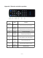


![hank yo_fo buyil_gaSamsung (}a_Te_a ]hs](http://vs1.manualzilla.com/store/data/005691502_1-2e8e29ffb67d0c8f7d0d701e3cb644b7-150x150.png)