1
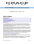
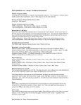
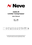
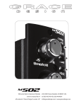
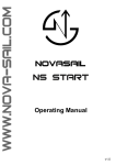
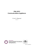
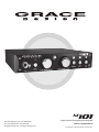
01 m1 4689 Ute Highway, Lyons, CO 80540 USA tel 1.303.823.8100 fax 1.303.823.8101 [email protected] / www.gracedesign.com single channel microphone preamplifier owner’s manual Rev A all contents © Grace Design/ Lunatec LLC Welcome and thanks for purchasing the Grace Design m101 microphone preamplifier and instrument DI. We design and build our products to be completely reliable and easy to use, so you can concentrate on making great recordings, not struggling with complicated equipment or difficult product manuals. While you will find the m101 is completely straightforward to use, we do ask that you spend a little time familiarizing yourself with this product manual to help avoid any common user difficulties. In the event that you do encounter any technical difficulties with this or any of our products, feel free to call us at 303-823-8100. Our office hours are 9 to 5, Monday through Friday, MST, or you may email any technical questions to: [email protected]. Also, please check out our web site (www.gracedesign.com) for the latest Grace Design product information, owners manuals and technical documents. Grace Design has been building audiophile-quality products for the recording industry over 15 years. The technology in the m101 is the result of extensive listening, field-testing and careful refinement. Your new m101 preamplifier represents a combination of absolutely pristine audio performance, robust mechanical construction and bombproof reliability at a reasonable price. Regardless of what audio sources you plan to record, your m101 will faithfully serve as an invisible link between your microphone or instrument and recording device. We sincerely hope our products help you achieve a new level of excellence in your work! The Grace Design Team Contents Important Safety Information 3 GENERAL3 SAFETY MARKING SYMBOLS 3 SERVICE INFORMATION 3 FEATURES4 front panel FEATURES 4 m101 connectiONS 5 OPERATING THE m1016 BASIC OPERATION 6 Using the Trim control 7 Using ribbon mic mode 7 Using the HPF 7 Rackmounting the m1017 Cable Diagrams 8 Basic Wiring Diagram 8 specifications 9 warranty information 10 Manual Revisions 11 101 m page 2 Important Safety Information GENERAL •Indoor use only •Ordinary Protection: This equipment should not be exposed to dripping or splashing. •Avoid placing objects filled with liquids, such as vases or glasses, on this equipment. •Class I Equipment (grounded type) •Electrical rating: 100-240V~ 50-60Hz 5W •Mains supply voltage fluctuations are not to exceed ±10% of the nominal supply voltage. •Pollution Degree 2 •Installation (Overvoltage) Category II for transient overvoltages. •Maximum Relative Humidity: <80% •Operation temperature range: 10 °C to 40 °C •Storage and transportation temperature range –40 °C to 70 °C •Maximum altitude: 3000m (9843 ft) •Equipment suitable for continuous operation •Weight: preamplifier 1.09kg (2.4lbs) SAFETY MARKING SYMBOLS CAUTION: READ ACCOMPANYING DOCUMENTS This symbol, located on the equipment and in this manual, refers to important instructions. Read this manual thoroughly before operating this equipment. WARNING: ELECTRICAL SHOCK HAZARD This symbol, located on the equipment and in this manual, indicates the potential for electrical shock hazard. SERVICE INFORMATION The Grace Design m101 contains no user serviceable components. Contact Grace Design for repair and upgrade information. In the event that your Grace Design m101 needs to be returned to the factory, contact us for a return authorization number. 101 m page 3 FEATURES • • • • • • • • • • • • • • • • • • • Fast, musical transimpedance amplifier architecture Fully balanced, transformerless XLR microphone input High impedance 1/4 inch instrument DI input Output connectors: XLR balanced, TRS balanced and TS unbalanced 12 position precision gold contact rotary switch gain control 0.5% precision metal film resistors in signal path High quality conductive plastic 10dB output trim control 75Hz 12dB/octave high pass filter Two color LED peak meter shows signal present and peak Ribbon mic mode (also great for dynamic mics)- Optimizes signal path for ribbon mics Aluminum 1/2 width 1U chassis / two units fit together in a standard 1U rack tray Sealed gold contact relays for signal switching High precision active balanced output circuit No electrolytic capacitors in the signal path Ultra clean 48 Volt phantom power Minimal internal signal wiring Built in universal AC power supply / no wall-wart! 5 year warranty on parts and labor Made in the USA front panel FEATURES 48V HIZ 0dB T RIM +10dB 10dB GAIN 65dB ribbon HPF 1/4” TRS instrument HI-Z input For high-impedance instrument or line level inputs. 48V PHANTOM POWER This switch provides 48 Volts to power condenser microphones. LED indicator illuminates red when active. GAIN CONTROL The gain control has 12 positions and adjusts the voltage gain on the microphone input from 10dB to 65dB in 5dB steps. When using the instrument input, the gain range is –10dB to 45dB in 5dB steps. 101 m page 4 PEAK INDICATOR The LED peak indicator, which monitors the signal at the output of the preamplifier, illuminates green at -14dBu and red at +16dB (10dB before clipping). TRIM CONTROL The trim control provides zero to +10dB of continuously variable output trim. RIBBON SWITCH Pushing this switch activates ribbon mic mode which optimizes the signal path for non-active ribbon mics. LED indicator illuminates white when active. HIGH PASS FILTER (labeled HPF) 75Hz, 12dB/Octave high pass filter. POWER STANDBY SWITCH The power standby switch activates the preamplifier circuitry. When depressed, the green POWER LED will illuminate. m101 connectiONS PUSH LEAD FREE 100-240VAC 5W MAX GRACE DESIGN BOULDER, CO USA Pb RoHS COMPLIENT AC LINE INPUT UNBAL OUT BAL OUT BAL OUT MIC IN A universal input AC supply provides power to the m101 with a voltage range of 100 - 240V, 50-60Hz. A standard three prong AC power cable is included with the m101. For safety, the power supply cord must be connected to a grounded outlet. UNBALANCED ¼” OUTPUT Unbalanced TS output connector. This output is wired tip signal, sleeve ground. All three outputs on the rear panel can be used simultaneously! BALANCED ¼” TRS OUTPUT Balanced TRS output connector. This output is wired with the tip positive, ring negative and sleeve ground. It is important to note that if either of the Balanced outputs are to be used unbalanced, a modified cable is required (see cable diagram 1 and 2 on page 8). It is not recommended to use an unbalanced ¼” plug in the balanced TRS output jack, because the sleeve of the unbalanced plug will short the inverting output amplifier 101 m page 5 to ground. While this will not cause damage to the preamplifier, it can cause unwanted distortion in the unbalanced signal. BALANCED XLR OUTPUT Balanced XLR line output connector. This output is wired pin 2 positive, pin 3 negative and pin 1 ground. MICROPHONE INPUT For connecting a microphone to the m101. This connector is wired pin 2 positive, pin 3 negative and pin 1 ground. 48V phantom power, if used, is supplied on pins 2 and 3. The Disconnect Device for the m101 is the Mains plug or the Appliance Coupler on the power supply cord. The Disconnect Device must remain accessible and operable. INSTRUMENT AND LINE INPUT Instrument and line level signal connections are made using the ¼” TRS jack on the front panel. This connector is balanced with the tip positive, ring negative and sleeve ground. Using the instrument input with an unbalanced source is simple if a mono ¼” jack is used, since the sleeve will automatically ground the inverting input (ring) when plugged in. HIZ When a plug is inserted into the instrument input, a sealed gold contact relay switches the preamplifier input source from the rear panel mic input connector to the front panel TRS jack. The input impedance of the instrument input is 1M Ohm unbalanced and 2M Ohm balanced, which is ideal for inserting high impedance 48V ribbon HPF Twell RIM 10dB 0dB as 10dB sources such asGAIN guitars 65dB with passive pickups, as +any instrument with a high level output. Please note that the gain range of the preamplifier when using the instrument input is –10dB to +55dB. OPERATING THE m101 BASIC OPERATION Turn the gain and trim controls fully counter-clockwise and check that the +48V phantom power is off. Connect the microphone to the preamplifier and then turn on the phantom power switch on if required. When sending a signal to a recorder that has fixed input levels, simply increase the gain until the optimum recording level is reached. When sending a signal to a recorder with a variable input, set the record level control on the recorder to 12 o’clock or midway between minimum and maximum, then set the gain on the m101 until the optimum recording level is reached. NOTE: It is important to observe proper microphone power sequencing when using phantom powered mics. Always make sure that the +48V phantom power is turned off and discharged before connecting or disconnecting a microphone. The red +48V LED indicates the presence of voltage at the microphone input connector. It will go out when the +48V supply is sufficiently discharged. 101 m page 6 Using the Trim control The trim control can be used for fine output level adjustment as well as for level riding during recording. The trim control can add an additional 10dB of gain for a total maximum preamplifier gain of 75dB. If the trim control is not needed for riding gain or providing extra gain boost then it should be left at zero (fully counter clockwise). Using ribbon mic mode Pushing the ribbon switch does three things: +48V phantom power is locked-out to prevent potential damage to ribbon microphones, the impedance of the mic input is raised from 8.1k Ohms to 20k Ohms, and the 48V DC blocking input capacitors are bypassed with sealed gold contact relays. The maximum gain available on the m101 is 75dB, which is achieved by setting the gain control to 60dB and the trim to 10dB. For recording low level sources with ribbon microphones, the m101 has ample available gain, sufficient for even the most demanding low-level recording scenarios. Note that if the +48V phantom power is on and then the ribbon mode is engaged there will be a momentary delay before the m101 enters ribbon mode. This is because the m101 logic circuitry waits for the +48V at the mic input to discharge before enabling ribbon mode. Likewise, if you are in ribbon mode and the +48V switch is on, then phantom power will turn on immediately if the ribbon mode switch is released. In general it is best practice to turn off the +48V phantom power before entering ribbon mode. The ribbon mode on the m101 is also ideal for many dynamic mics. Using the HPF The high pass filter, sometimes referred to as a bass roll-off, starts at 75Hz. This 12dB/octave filter is optimized for minimum phase shift. The most common uses for this are in situations where low-end rumble from mechanical sources or wind are present, to reduce excessive proximity effect, or to simply help reign in excessive bass during recording. Rackmounting the m101 The m101 chassis has a #10-32 threaded insert mounting hole on the bottom towards the back. Two m101s can be mounted side by side in a standard 1U rack tray. Use a #10-32 x 1/2” or a #10-32 x 3/8” machine screw. Do not use a screw longer than 1/2”. mounting hole chassis underside 101 m page 7 Cable Diagrams Use these cables only when an additional unbalanced output is needed. Balanced Output 1/4” TRS Unbalanced 1/4” HOT GROUND TIP RING SHIELD SLEEVE RING IS OPEN 1/4” TRS Balanced Output to 1/4” Unbalanced input Balanced Output XLR Unbalanced 1/4” HOT 1 2 GROUND SHIELD 3 (OPEN) XLR Balanced Output to 1/4” Unbalanced input Basic Wiring Diagram The following is a basic overview of some of the more common wiring possibilities for the m501. All applications will vary, so please feel free to contact your dealer or us directly for setup and wiring information. 48V HIZ 10dB GAIN 65dB 0dB T RIM +10dB ribbon HPF PUSH LEAD FREE Instrument Instrument Amplifier 101 m page 8 100-240VAC 5W MAX GRACE DESIGN BOULDER, CO USA Pb RoHS COMPLIENT Mixer / PA system UNBAL OUT BAL OUT BAL OUT MIC IN microphone Recorder / Converter / DAW / Soundcard / Interface specifications GAIN RANGE (5dB steps) Mic input Hi-Z input Output trim control 10-65dB -10-45dB 0 to +10dB THD+N @ 20dB Gain +20dBu out @ 40dB Gain +20dBu out @ 60dB Gain +20dBu out <0.00085% <0.0010% <0.0050% INTERMODULATION DISTORTION @ 40dB Gain +20dBu out SMPTE/DIN 4:1 7kHz/50Hz <0.0020 NOISE - REFERRED TO INPUT 50Ω source 150Ω source 600Ω source <-130dB <-128dB <-124dB CMRR 100Hz 1kHz 10kHz >68dB >75dB >65dB PHASE DEVIATION (HPF off) 50Hz-25kHz <6° FREQUENCY RESPONSE Mic input @ 40dB Gain -3dB Mic input @ 40dB Gain -0.5dB Hi-Z input @ 20dB Gain -3dB Hi-Z input @ 20dB Gain -0.5dB 4.5Hz-390kHz 10.5Hz-140kHz 2.5Hz-195kHz 6Hz-74kHz IMPEDANCE Mic input Mic input, Ribbon mode Hi-Z input (unbalanced) Hi-Z input (balanced) Balanced Output Unbalanced Output 8.1kΩ 20kΩ 1MΩ 2MΩ 300Ω 150Ω PEAK LED METER Green threshold Red threshold -14dBu +16dBu MAXIMUM OUTPUT LEVEL 100k Ohm load, 0.1% THD +25dBu WEIGHT and DIMENSIONS 2.4 lbs 1.09 kg H1.7” x W8.5” x D9.0” H4.3cm x W21.6cm x D22.8cm POWER CONSUMPTION 100-240VAC 5 Watts Max 101 m page 9 warranty information 101 m • Grace Design warrants all of our products to be free of defective parts and workmanship for a period of five years. • This warranty period begins at the original date of purchase and is transferable to any person who may subsequently purchase the product during this time. • This warranty excludes the following conditions: normal wear and tear, misuse, customer negligence, accidental damage, unauthorized repair or modification, cosmetic damage and damage incurred during shipment. • During the time of this warranty, Grace Design will repair or replace, at its option, any defective parts or repair defective workmanship without charge, provided the customer has appropriate proof of purchase and that the product has its original factory serial number. • Customers within the US are responsible for all inbound freight charges to Grace Design’s facility, while Grace Design will pay for return freight charges via ground service. Customers outside the US must contact their distributor for warranty / product return details. • In order for Grace Design to provide efficient and timely warranty service, it is important that you mail the completed warranty registration card enclosed with all of our products within 10 days of the original date of purchase. You may also register your product directly with Grace Design by telephone (303-823-8100 Monday-Friday 9:00am to 5:00pm MST), or you can register your product online at www.gracedesign.com. • This warranty is in lieu of all other warranties whether written, expressed, or implied, INCLUDING ANY WARRANTIES OF MERCHANTABILITY OR FITNESS FOR A PARTICULAR PURPOSE. In no event will Grace Design be liable for lost profits or any other incidental, consequential or Exemplary damages, even if Grace Design is aware of the possibility of such damages. • In no event will Grace Design’s liability exceed the purchase price of the product. This warranty gives the customer specific legal rights. The customer may also have other rights, which vary from state to state. Some states do not allow limitations on implied warranties or consequential damages, so some of the limitations of the above may not apply to a particular customer. page 10 Manual Revisions Revision Page A all Change Date Initials 4/7/08 edg 101 m page 11