1
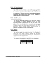
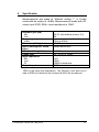
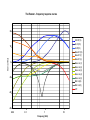
The Rooster device and logo copyright © 2007 Jon Bailes. All rights reserved.
©Thermionic Culture Ltd., May 2014
1
WARNING
For your personal safety, please read this operating manual and
warning thoroughly before using the equipment.
This unit must be installed in such a manner that operator access
to the mains plug is maintained. Where the product is to be rack
mounted, this may be achieved by having access to the
disconnection device for the whole rack.
To reduce the risk of electric shock, it is essential that the unit is
disconnected from the mains supply before removing the cover.
Please also note that the power supply capacitors within this unit
can remain charged even after the mains supply has been
disconnected. It is essential that these capacitors are discharged
after the mains supply has been disconnected and the covers
have been removed.
In the event that this unit has been dropped or has suffered an
impact, an electrical safety test must be carried out before
reconnection to the mains supply.
This equipment is not intended for use in explosion hazard
environments. It must be used and stored in studio conditions,
such that the ambient relative humidity does not exceed 80%, nor
is the temperature to be allowed to drop to a level, which would
cause dew point to be reached.
Please ensure that adequate ventilation is provided and that the
ventilation slots are not obstructed. When rack mounting this
equipment, a fan may be required to provide sufficient airflow.
It is not advisable to operate this equipment if all valves are not in
place and working, as voltages will rise and components may
overheat and fail.
©Thermionic Culture Ltd., May 2014
2
CONTENTS
Section
Page
1
Introduction
3
2
Controls and meters
4
2.1
Phase switch
4
2.2
I/P switch
4
2.3
DI socket
4
2.4
I/P level control
4
2.5
Base lift control
4
2.6
Mid/Hi lift control
5
2.7
2.5k/4k/Hi switch
5
2.8
Mid Cut control
5
2.9
Bass Cut switch
5
2.10 LPF switch
6
2.11 Mode switch
6
2.12 Attitude switch
6
2.13 O/P level control
7
2.14 Off/48V switch
7
2.15 Meters
7
3
Operational hints and tips
8
4
Connections
9
5
Servicing and maintenance
10
5.1
Valves
10
5.2
Operating voltages and fuses
10
6
Specification
©Thermionic Culture Ltd., May 2014
11
3
1
Introduction
The Rooster 2 is a valve device dedicated to bringing
together three facilities in one unit. It provides a high quality
Mic / DI / Line pre-amp, suitable for any type of microphone,
DI or line source. Then comes a unique sounding award
winning EQ section, specially designed by Vic Keary,
comprising broad but very useable frequency bands with a
‘vari slope’ curve for bass and top. This is also a feature of
the Earlybird 2 series of mic-amps. Finally, the ability to
change the amount of distortion, or THD, of the unit as a
whole is provided by the “Attitude” control, combined with the
‘Mode’ switch. All of these features are available on both of
the unit’s 2 channels.
The Rooster 2 will provide everything from a warm, clean
sounding valve mic-pre, suitable for any application, to a
characterful overdriven processor with powerful EQ, as
adaptable for adding dirt and edge to mics as it is for
mixdown treatment.
The user has control over the amount of THD that The
Rooster 2 will add to the signal as well as the kind of
harmonics included in that THD. This is achieved by using a
5654 pentode valve. The control over gain given to the user
can also be used to obtain more or less THD included in the
output signal. In addition to this the EQ section can be used
to tailor the sound of the distortion at high THD levels or it
may act as a more conventional tone control at low distortion
settings.
©Thermionic Culture Ltd., May 2014
4
2
Controls and meters
2.1
Phase switch
Controls the absolute phase of the signal. The ‘NonInv’ position does not alter the phase of the signal
applied to the input. Whereas, the ‘Invert’ position puts
the signal at the output 180º out of phase with the
input signal.
2.2
I/P switch
In the ‘Mic’ position, the unit takes the input signal
from the ‘Mic In’ XLR socket at the rear of the unit and
gives up to 79dB of gain to a mic level signal. When
set to ‘Line’ the unit takes the input signal from the
‘Line In’ XLR socket and gives up to 45.5dB of gain to
a line level signal.
2.3
DI socket
This socket provides an unbalanced, high impedance
input for any low or instrument level input sources.
This input will cut any other input when connected, so
it will become the input to The Rooster 2 regardless of
the position of the I/P switch.
2.4
I/P Level control
The ‘I/P Level’ control gives continuously variable
adjustment over the input gain of The Rooster 2 in
whatever mode it is being used.
2.5
Bass Lift control
The ‘bass lift’ control gives continuously variable
adjustment over the amount of bass boost applied to
the signal. The unique ‘vari slope’ bass lift curve can
be thought of as a ‘shelving’ type curve at low
amounts of boost. As the boost increases the low end
©Thermionic Culture Ltd., May 2014
5
‘tips up’, giving an emphasis to lower frequencies and
this adds an impression of size to the bass end.
2.6
Mid/Hi Lift control
The ‘Mid/Hi Lift’ control gives continuously variable
adjustment over the amount of mid or high frequency
boost applied to the signal. The ‘2.5k/4k/Hi’ switch,
described next, determines the actual frequency range
being lifted.
2.7
2.5k/4k/Hi switch
This switch provides the user with a very broad lift at
2.5 & 4kHz (highest peak frequencies) with some top
lift as well and a ‘vari slope’ shelving type curve on the
‘hi’ setting. At maximum boost the peak point for the
‘hi’ setting will be 10kHz.
2.8
Mid Cut control
The ‘mid cut’ control gives continuously variable
adjustment over the amount of mid range frequencies
being cut from the signal. The curve used is a bell
shape curve that becomes sharper as more cut is
applied. The centre of the curve is at 700Hz.
2.9
Bass Cut switch
The ‘Bass Cut’ switch is a stepped control with the
following options available :-
·
·
·
·
·
·
0 Flat response;
1 High pass filter operating below 30Hz;
2 6dB per octave curve, 3dB down at 120Hz;
3 6dB per octave curve, 3dB down at 350Hz;
4 Shelving curve, 3dB down at 800Hz;
5 Shelving curve, 3dB down at 3kHz
Positions 2-5 have a steeper cut below 30Hz.
©Thermionic Culture Ltd., May 2014
6
2.10 LPF switch
Switches a Low Pass Filter in or out of circuit after the
distortion valve. This is included because, in situations
where all stages of The Rooster 2 are being pushed
into extreme distortion, it may be necessary to tame
the excessive high frequency content created by the
distortion itself. This control can provide a smoother
kind of extreme distortion to the signal. This filter starts
acting above 5kHz and is 6dB down at 10kHz.
2.11 Mode switch
This switch determines whether The Rooster 2’s 5654
valve is to be used as a Triode or Pentode valve.
Triode valves tend to give predominantly 2nd order
harmonic distortion when driven hard whereas
Pentode valves give predominantly more 3rd order
harmonics. 2nd order harmonics will tend to sound
smoother and 3rd order harmonics will give a more
aggressive effect.
2.12 Attitude switch
The ‘Attitude’ switch allows the user to determine how
much distortion, or THD The Rooster 2 will add to the
signal. At position ‘1’ The Rooster 2 is capable of
delivering a very clean signal (well below 0.1%), but
as the control is stepped towards ‘Max’ the distortion
provided by The Rooster 2 will increase.
This does also rely on the setting of the ‘I/P Level’
control, which if turned down will decrease distortion
and when turned up increases distortion. With both
controls set to maximum the distortion will be very
extreme, and the output control will need to be
reduced to a low level.
©Thermionic Culture Ltd., May 2014
7
2.13 O/P Level control
The ‘O/P Level’ control is a continuously variable
attenuator that controls the output level of The Rooster
2. A cleaner signal is obtained when the control is set
to maximum. Turning the output control down towards
minimum and driving the input of The Rooster 2
harder results in more distortion.
2.14 Off/48V switch
The Off/48V switches located at the right hand side of
The Rooster 2, control whether or not the 48V
phantom power is applied to the ‘Mic In’ XLRs. This
allows the use of phantom powered microphones.
Please ensure that these are switched to the ‘Off’
position when using ribbon microphones or
passive equalisers such as The Pullet.
2.15 Meters
The meters read the output level of The Rooster 2
after the ‘O/P Level’ control, serving as a basic
indication of the output level feeding the next piece of
equipment in the signal chain.
The nominal thresholds of each LED are as follows:Yellow
Green
Red
©Thermionic Culture Ltd., May 2014
-20dB
-4dB
+6dB
8
3
Operational hints and tips
To use The Rooster 2 as a clean, high quality, valve mic
amp. Set the ‘O/P Level’ control to '8', the ‘Attitude’ switch to
‘1’ and the 'Mode' to 'Triode', then use the ‘I/P Level’ control
to obtain the desired amount of gain. If more gain is required
simply increase the ‘Attitude’ switch and/or output level until
the gain is satisfactory.
The ‘LPF’ filter becomes especially useful when heavily
distorting DI inputs, like bass instruments for example. As
the distortion becomes extreme the high frequency content
can start to sound more ‘clipped’ and stands out from the
actual sound of the instrument. Using the ‘LPF’ filter will
tame the problem frequencies and result in a smoother more
musical sounding distortion, allowing the user to push The
Rooster 2 into even more distortion if desired.
The Rooster 2 can act as a subtle enhancer on mixdown.
For example, a vocal sound can be given more life and cut
through a mix better if a little overdrive is added plus some
additional mid range or top EQ. Try the ‘Attitude’ switch at ‘4’
and add a little mid lift at 4k, the ‘Pentode’ setting will make
the vocal slightly more aggressive if required.
Drum microphones can benefit greatly from being recorded
through The Rooster 2. A mic that is placed to capture the
sound of the whole kit with a little room sound included
would be ideal. The ‘Attitude’ can be increased to give a
similar effect to compression. The ‘Bass Lift’ can also be
used to give a very large bottom end to the drums. The
‘Triode’ and ‘Pentode’ settings will govern how smooth or
harsh the user wants the overall effect to be.
The bass lift and bass cut can be used together to shape the
sound. Try heavy bass lift and bass cut at '4' or '5'.
©Thermionic Culture Ltd., May 2014
9
4
Connections
There are 3 XLR connections per channel at the rear of The
Rooster 2, plus one DI jack input per channel, on the front
panel.
‘Mic In’ is a balanced input, which all microphones should be
plugged into. The connector is a 3 pin female XLR. (The
input signal should be applied to pins 2 and 3. Pin 1 is
ground).
‘Line In’ is the female 3 pin XLR socket that any line level
signals (+4 dBV) should be sent to. These inputs are
balanced (see ‘Mic-In’ for connections). If an unbalanced
source is used, Pin2 should be signal and pins 1 and 3
should be ground.
‘O/P’ is the male 3 pin XLR socket that the line level output
signal (+4 dBV) appears at. The output is transformer
'balanced' (ie. floating) and can be equally well connected to
a balanced or unbalanced piece of equipment. Pins 2 and 3
are signal and pin 1 is ground.
‘DI’ is the jack socket on the unit’s front panel. This provides
a high impedance signal for all low level and instrument level
signals. When this input is connected it will disable all other
inputs on this channel and operate regardless of the position
of the ‘I/P’ switch.
©Thermionic Culture Ltd., May 2014
10
5
Servicing and maintenance
5.1
Valves
All valves are selected to ensure that the unit gives
optimum and consistent performance across both
channels.
Although Thermionic Culture Ltd. guarantees the
valves for twelve months, they can last up to 20 years.
Spare valves can be obtained from Thermionic Culture
Ltd.
The Rooster 2 Valve complement is:
Input:
Distortion:
Output:
5.2
12AX7 / ECC803 / ECC83 (2 off)
5654 (2 off)
PCF 80 (2 off)
Operating voltages / fuses
The Rooster 2 can be set to operate from either 230V
or 115V 50/60 Hz AC. The appropriate mains input
voltage can be selected on the red switch located next
to the mains inlet.
Note: Mains fuses must be replaced in accordance
with the following table.
230V
115V
©Thermionic Culture Ltd., May 2014
T315mA
T630mA
11
6
Specification
Measurements are made at ‘Attitude’ setting ‘1’. in Triode
mode with an output of +4dBu. Measurements made with AC
mains input 236V 50Hz. Load resistance is 10kΩ.
Available gain (dB)
Mic
Line
Frequency response
±1dB
Distortion (THD @ 1kHz)
Noise (unweighted, 30kHz
filter)
MOL (2% THD @1kHz)
Phase shift
Input impedance
Mic
Line
DI
Output impedance
56 (87 with Attitude at max. (P))
24
10Hz to 45kHz
≤0.05%
≤95dB below MOL
≥+25dBu
24º (6.6%) at 10kHz
1kΩ
10kΩ
100kΩ unbalanced
600Ω
10kΩ is the ideal load impedance. The Rooster 2 will work into a
load of 600Ω, but distortion will increase & MOL will be reduced.
©Thermionic Culture Ltd., May 2014
12
The Rooster - frequency response curves
20
2k5 lift(10)
Hi Lift(10)
4k lift(10)
Bass lift (10)
Bass lift (7)
Bass lift (3)
Bass cut (1)
Bass cut (2)
Bass cut (3)
Bass cut (4)
Bass cut (5)
Mid Cut(9)
Mid Cut (5)
LPF
Gain (dBu)
10
0
-10
-20
-30
0.02
0. 1
1
Frequency (kHz)
10
100
Thermionic Culture Ltd., Harlow, Essex, UK
Tel: +44 (0)1279 414770 email: [email protected]
©Thermionic Culture Ltd., May 2014. Printed in UK.