1
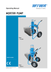
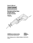
Basic Principles of
Asphalt Compaction
Compaction methods
Compaction equipment
Rolling technique
Masthead
© BOMAG GmbH, Fayat Group, Germany, all rights reserved
Publisher:
BOMAG GmbH, Hellerwald, D-56154 Boppard
Project management:
Dipl. Ing. H.-J. Kloubert, BOMAG GmbH, Boppard
www.bomag.com
Publisher's notes: The publication in its entirety is protected by copyright . All details, data, results etc.
contained in this book have been created by the project management to the best of knowledge and
reviewed with greatest care. However, errors as to the contents can never be completely ruled out. The
project management can therefore not assume liability for any possible incorrectness as to the contents
of this book.
1. Edition 02/2009
Foreword
The asphalt layers of a road pavement should
be able to reliably carry the traffic loads and to
discharge these to the substructure or subbase, in
order to prevent harmful deformation. This equally
applies for load burdens resulting from weather and
temperature stress. Besides the mix composition
and the paving, the compaction of the mix is of
utmost importance with respect to the quality and
the service life of the road. On the construction
site successful compaction mainly depends on
the compaction technique, the knowledge and the
experience of the roller driver.
In this book we present an overview of compaction
techniques and equipment. It contains explanations
to the different rolling patterns and a number of
basic rules and notes for successful compaction
of rolled asphalt. The BOMAG Asphalt Compaction
Handbook should serve as source of information
for practicians involved in pavement construction
and facilitate the use of compaction equipment in
asphalt construction.
Table of
contents
1. Basic principles of
asphalt compaction ...............................2
7. Preparing the
compaction equipment .....................27
1.1 Principles.........................................................2
1.2 Influence of the mix composition .....................3
1.3 Influence of the mix temperature.....................4
8. Rolling patterns ....................................29
2. Compaction methods
2.1
2.2
2.3
2.4
Initial compaction with the finisher ..................5
Static compaction............................................6
Vibratory compaction ......................................7
Controlled compaction with ASPHALT MANAGER8
3. Compaction equipment ......................9
3.1 Hand-guided compaction equipment
- Tampers
- Vibratory plates
- Hand-guided tandem rollers ........................9
3.2 Light tandem rollers ......................................10
3.3 Combination rollers .......................................10
3.4 Pneumatic tired rollers ..................................10
3.5 Articulated tandem rollers .............................11
3.6 Pivot steered tandem rollers .........................12
3.7 Steering systems ..........................................12
4. Equipment characteristics of
tandem and combination rollers ..15
4.1 Split and non-split drums...............................15
4.2 Sprinkling system ..........................................15
4.3 Speed level switch .........................................16
4.4 Edge compressing and cutting equipment ....17
4.5 Chip spreader ................................................19
4.6 ROPS - Roll Over Protection Structure .........20
4.7 Working light ..................................................20
5. Technical data of
asphalt rollers .......................................21
6. Compaction performance................23
8.1 Compacting when paving with one finisher ...29
8.2 Compacting when paving with two finishers ..30
8.3 Asphalt compaction with tandem rollers only . 30
8.4 Asphalt compaction with rubber tired
and tandem rollers ........................................31
8.5 Compacting asphalt layers with crown ............ 31
8.6 Compacting in curves ....................................32
8.7 Compacting seams and joints
- Transverse joints
- Longitudinal joints ......................................32
8.8 Application of chips to wearing courses ........33
9. Compaction and paving faults .......35
10.Basic rules for compaction work
on asphalt mixes..................................37
11.Compaction measurement and
documentation systems...................39
12. APPENDIX ..............................................43
A1 Road construction classes.......................43
A2 Mix types and layer thicknesses ..............43
A3 Asphalt base course ................................44
A4 Asphalt binder course ..............................44
A5 Asphalt wearing courses .........................45
- Asphalt concrete ......................................46
- Stone mastic asphalt ...............................48
A6 Combined surface-base-course
construction .............................................50
A7 Bitumen types ..........................................50
List of rules and literature..................52
1
1. Basic principles of asphalt compaction
1.1 Principles
Rolled asphalts are divided into base courses,
asphalt binder courses and asphalt wearing courses.
Asphalt concrete, stone mastic asphalt and porous
asphalts are used for asphalt wearing courses.
The laid mix must be compacted to such a degree
that an increase in density or a reduction of porosity
in the asphalt layer is achieved. On this air voids
one must make sure that the demanded degree of
compaction is reached and that the limit values for
the void content are complied with.
This results in an enhanced stability of the layers
and thus in a higher resistance against deformation.
Good compaction also has a positive effect on the
wear resistance of the wearing course.
riding quality, skid resistance,
impermeability
Asphalt wearing course
impermeability
shear resistant
Asphalt binder course
Asphalt base course
bearing capacity
pavement
subbase
capping layer
formation
subgrade/
embankment
Fig. 1 Structure and properties of an asphalt road
At the same time the compaction machine should
produce a level asphalt layer as desired for driving
comfort, and a wearing course with closed and
smooth surface structure, but with maximum grip.
Objectives of compaction
Compaction
performance
Quality
characteristics
Higher density
Evenness
Defined air voids
Skid resistance
High stability and
wear resistance
Closed surface
Fig. 2 Objectives of compaction
2
1
1.2 Influence of the mix composition
The composition of asphalt mixes varies widely in
dependence on the expected loads caused by traffic
and weather. They therefore also have quite different
compaction properties. The compactibility of the
asphalt mix depends on the composition of minerals
as well as the quality and viscosity of the bitumen
and thus also on the temperature of the mix.
mix design
gravel
crushed
aggregate
low
stone content
high
stone content
small max.
stone size
high max.
stone size
properties
low
filler content
high
filler content
high penetration
bitumen
application
• low stability
• sensitive to
shoving
• sensitive to
rippling
• easy to
compact
• lightly
trafficked roads
• secondary roads
• local roads
• cycle ways
• parking areas
• high stability
• high internal
friction
• difficult to
compact
• heavily
trafficked roads
• motorways
• country roads
• national roads
• airports
low penetration
bitumen
Fig. 3 Composition of asphalt mix
Asphalt mixes for roads with high traffic loads are
designed for high deformation resistance. They are
characterized by a bulky mineral skeleton structure,
i.e. high stone contents, coarse grain, a high proportion of crushed grains in the sand range (crushed
sand) and stiff bituminous mortar. These mixes are difficult to compact and require high compaction efforts.
They are normally easy to compact, therefore do
not require high compaction efforts, but, due to their
lacking stability when hot after laying, may react very
sensitively to the use of heavy compaction equipment
or to a too early start of compaction work.
This may quickly result in material displacements
and the formation of bow waves.
Asphalt mixes for roads with low traffic volumes
normally contain a lower proportion of stones, a considerably high amount of natural sand and soft
bituminous mortar.
Mix instable
(soft)
Mix stiff
(stiff)
Low stability
High stability
Fig. 4 Rolling behaviour with different asphalt mixes
3
The temperature of the mix during compaction is of
high significance for the compaction effort required.
With too high mix temperatures the compaction
by a roller is supported by the low viscosity of
the bitumen. The bitumen acts as a lubricant and
reduces the internal friction in the mineral mix.
Due to the progressing stiffening of the bitumen
caused by cooling, the compaction effort increases
considerably under low temperatures.
Compaction therefore should, as a general rule,
be started as soon as possible. Compaction
temperatures between 100° and 140°C have been
found most favourable for the conventional bitumen
types. Compaction should be completed when
the temperature has dropped to between 80° and
100°C.
Compaction effort
1.3. Influence of the mix temperature
End of compaction
Favourable compaction
temperature
Start of
compaction
Mix temperature in °C
Fig. 5 Effect of the compaction temperature on
the compaction effort
4
2. Compaction methods
2.1 Initial compaction with the finisher
With a low pre-compaction by the finisher the use
of a light roller to initially press down the mix is a
very sensible decision, because too heavy roller
may adversely affect the evenness of the layer and,
depending on the stability of the hot mix, may cause
undesired displacements and misplacements in the
material.
High initial compaction by the finisher has a favourable
effect on the evenness of the layer and, at the same
time, enables an early start of compaction, while
the mix temperatures are still high. This favourably
supports the compaction effect of the rollers, and
final compaction can be achieved with only a few
roller passes.
In such a case tandem vibratory rollers should drive
the first two passes without vibration.
Fig. 6 Initial compaction by the finisher
Fig. 7 Laying and compacting with the BOMAG BF 600 P and the BOMAG BW 174 AD-AM
5
2
2.2 Static compaction
Static compaction is achieved by the deadweight of
the roller. Tandem rollers and pneumatic tired rollers
are used for this purpose. Compared with vibratory
compaction the compaction effect is relatively low.
With tandem rollers compaction is influenced by the
static linear load (kg/cm) of the drum, with pneumatic
tired rollers by the wheel load (t) and the tire inflation
pressure (MPa).
Static compaction with tandem rollers makes sense if
the initial compaction by the finisher was only low, if
the asphalt mix is easy to compact, in case of porous
asphalts and thin layers and when ironing wearing
courses.
Linear load 10 - 30 kg/cm
Aspahlt
wearing course
Asphalt
base course
Gravel-sand
Fig. 8 Static compaction with tandem rollers
With the kneading and flexing effect of their wheels
pneumatic tired rollers achieve a special quality
in static compaction. It leads to a homogeneous
distribution of the mix and closes the pores on the
surface. The main areas of application are the preprofiling and processing of easy to compact mixes
Application
• Surface treatment
• Initial compaction of sensitive asphalt layers
• Surface sealing on wearing courses
Asphalt binder course
Sand
Contact pressure
0.20 - 0.80 MPa
Compaction effect
Ground contact and kneeding effect
Important machine characteristics
• Wheel load
• Tire inflation pressure
Fig. 9 Static compaction with pneumatic tired roller
6
and the finish of the surfaces of wearing and base
courses or of light traffic roads. Here the pneumatic
tired roller is normally combined with a smooth
drum roller.
2.3 Vibratory compaction
Vibratory rollers are very powerful, versatile and
require considerably less passes than static rollers.The
vibration reduces the internal friction in the mineral
mix, so that the interaction between deadweight
and dynamic load increases the density. Besides
the static linear load, other factors like vibrating
mass, frequency and amplitude are therefore also
decisive for the compaction effect.
For optimal compaction of different layer thicknesses
bigger tandem vibratory rollers, in most cases with
two amplitudes and two frequencies, are required.
high
Amplitude
low
Amplitude
Compaction principle
static pressure
and dynamic energy
Application
• asphalt surfacing
• asphalt bases
• overlay compaction on
granular bases
Application
• asphalt bases
• granular bases
• cement bound bases
• subbases
key parameters
• static linear load
• vibrating mass
• amplitude
• frequency
Aspahlt wearing course
Asphalt base course
Gravel-sand
Fig. 10 Vibratory compaction using tandem rollers with circular exciter system
The rolling speed should be 3 to 6 km/h.
Thickness of
the asphalt layer
d (cm)
2
4
6
10
14
18
Chip mastic
d=2
d=4
porous asphalt d = 4
Too many passes with vibration can cause harmful
loosening of material and disturbances in the
structure.
Number of passes with vibration
with various tandem vibratory rollers
4t
7t
10t
2-4
4-6
4-8
6-8
1-2 (K)
2-4 (K)
4-6 (K)
4-8 (K, G)
6-8 (G)
6-8 (G)
1-2 (K)
2-4 (K)
2-4 (K)
4-6 (K, G)
4-6 (G)
4-8 (G)
1-2 (K) + stat. pass
4-6 (K) + stat. pass
1-2 (K) + stat. pass
4-6 (K) + stat. pass
1-2 (K) + stat. pass
K = low amplitude
G = high amplitude
Assumption:
Compaction
temperature > 100°C
4t = Machine with
one amplitude
only
1 pass = 1 pass in
forward or in reverse
direction
Fig. 11 Typical values for the number of vibratory passes
7
2
2.4 Controlled compaction with ASPHALT MANAGER
With controlled compaction the required compaction
energy is determined and automatically adjusted. In
automatic mode no adjustments must be made by
the driver. Rollers with ASPHALT MANAGER work
with a directed exciter system; it is automatically
regulated. During compaction the effective amplitude
is optimally and continuously adapted to the actual
conditions. Grain damages and disturbances in the
structure of the asphalt are effectively prevented.
Besides working in automatic mode, the roller
driver is also able to pre-select a certain direction of
vibration (manual mode).
low dynamic energy
due to horizontally
directed vibrations
Gravel-sand
There are six different directions available, ranging
from vertical to horizontal (similar to oscillation). Due
to their excellent adaptability, rollers with ASPHALT
MANAGER are highly suitable for the complete
spectrum of asphalt applications. Manual mode
with horizontal vibrations is recommended for the
compaction of layers on bridges, on/in multi-storey
car parks or in the vicinity of structures which may
be sensitive to vibrations.
Compaction effect
Deadweight and dynamic energy,
the compaction effect is automatically
adapted to compactibility of material,
layer thickness and subbase.
high dynamic energy
due to vertically
directed vibrations
Application: all soil types,
granular bases and subbases
Fig. 12 Vibratory compaction ASPHALT MANAGER with directed exciter system
•
Universal use
•
Higher compaction performance without the risk of grain destruction
•
Uniform compaction by continuous adaptation of the compaction energy
•
Better evenness and more uniform surface structure on asphalt layers
•
Unproblematic behaviour of the roller when compacting along edges and joints
•
Optimally suited for layers on bridges and in the vicinity of constructions that may be
sensitive to vibrations (similar to oscillation)
•
Equipped with compaction and temperature measuring facilities
Fig. 13 Benefits of rollers with Asphalt Manager
8
3. Compaction equipment
3.1 Hand-guided compaction equipment
Tamper
Tampers belong to the smallest compaction
machines used on construction sites. They are
used under confined spatial conditions, where
larger compaction machines cannot be used. They
are available in the weight class from 60 - 80 kg.
Tampers are powered by modern 4-stroke gasoline
engines or, more rarely, by diesel engines. The
engine driven eccentric (crank drive) causes the
fast vertical movement of the tamper foot.
Fig. 14 Tampers
Vibratory plates
Forward running and reversible vibratory plates
are used for the compaction of small or confined
asphalt surfaces. They are available in the weight
range from 50 - 150 kg with working widths ranging
from 45 to 60 cm. Vibratory plates are powered
by gasoline or diesel engines. The exciter system
(directed vibrator) is driven via V-belt and centrifugal
clutch. The movement direction of reversible plates
is achieved by adjusting the directed vibrator
accordingly.
Fig. 15 Vibratory plate
Hand-guided tandem rollers
Hand-guided tandem rollers are available in the
weight range from 600 - 1000 kg with working
widths ranging from 60 cm - 75 cm. Both drums are
either mechanically driven by a 2-stage mechanical
gearbox, or by a hydrostatic drive. These rollers
work with double vibration.
Fig. 16 Hand-guided rollers
9
3
3.2 Light tandem rollers
Light, articulated tandem rollers are ride-on rollers
in the weight class from 1.3 to 4.2 t and working
widths ranging from 80 cm to 138 cm. They are
designed with hydrostatic travel and vibration
systems for both drums.
Fig. 17 light, articulated tandem rollers
3.3 Combination rollers
Combination rollers are designed with a vibrating
drum and a wheel set.They are particularly suitable
for asphalt compaction on inclinations, for repairs
and patchwork in the construction of footpaths,
cycle paths and car parks. Combination rollers are
available in the class ranging from 1.5 to 2.5 t and
also from 7 to 10 t.
Fig. 18 Combination roller
3.4 Pneumatic tired rollers
Pneumatic tired rollers are designed with a
steering/oscillating axle at the front and a rigid drive
axle at the rear. With an additional ballast of 10 t
the deadweight of these rollers can be increased
to 24 or 27 t respectively. The compaction effect
is achieved with the deadweight of the machine
and the kneading and flexing effect of the wheels.
The tire inflation pressure affects the efficiency of
compaction (e.g. the number of passes).
Fig. 19 Pneumatic tired roller
10
Both axles are equipped with 4 compactor wheels
each; the wheels overlap (track offset) by approx.
40 mm).
3
Fig. 20 Wheel position of the pneumatic tired roller
3.5 Articulated tandem rollers
Heavy tandem rollers in the weight range from 7 to
14 t with working widths of 1.50 m, 1.68 m, 2.00 m
and 2.13 m are used for medium to large scale
construction projects.
Vibration:
• only front
• or only rear
• or both drums
Drums:
• split or non-split
Fig. 21 Articulated tandem rollers
On rollers with central oscillating articulated joint
both drums remain in track, even when cornering
(left/right). The rollers have a standard crabwalk
facility of 170 mm to either side. This facilitates
among others the compaction along edges and the
moving away from lateral limitations.
Fig. 22 Steering concept (articulated steered)
11
3.6 Pivot steered tandem rollers
Pivot steered tandem rollers are available in the 7
and 10 t weight range with working widths of 1.50 m
and 1.68 m.
The travel and vibration drives are hydrostatic
Vibration: front and/or rear
Drums: front and rear: split or non-split
Fig. 23 Pivot steered tandem rollers
The BOMAG pivot steering is a particularly convenient electric steering system. The driver can choose
from the following settings:
•
•
•
•
•
Fig. 24 Types of steering with pivot steering
Diagonal (left/right)
Only front
Only rear
Synchronous steering (both drums)
Automatically front or rear depending
on travel direction
3.7 Steering systems
Fig. 25 Pivot steering
On pivot steered rollers both drums can either
be steered together (synchronous steering) or
individually at front or rear. Pivot steered rollers
are additionally designed with a large adjustable
crabwalk (up to 120 mm).
12
Pivot steered rollers are optimally suited for
both small scale constructions (e.g. crossings,
roundabouts, sharp bents) as well as large area
projects (e.g. A-roads and motorways).
max. to
120 cm
3
Fig. 26 Crabwalk
On pivot steered rollers full advantage can be made
of the large "crabwalk" (up to 120 mm):
•
The weight of the roller is distributed over
a larger area; the roller does not sink in so
deep.
•
Unproblematic initial compaction of sensitive
materials with high asphalt temperature
•
•
Final "ironing" of large areas.
The roller has a larger distance to the still
instable edge of the asphalt layer.
Fig. 27 Articulated steering
Tandem rollers with articulated steering have a
central articulated oscillating joint between the
drums.
This ensures that both drums run in track, even
when cornering. When using the crabwalk the rear
drum is offset either to the left or the right. Due to
their design the tracks of tandem rollers can be
offset by < 17 cm.
Practical benefits of the crabwalk facility:
•
•
•
Unproblematic steering away from curb
stones
Rational working with the
edge compressing cone
Avoids sharp-edged track marks
from the drum edges in the asphalt surface
13
14
4. Equipment characteristics of tandem and combination rollers
4.1 Split and non-split drums
Less shearing forces in tight curves
non split
split
Tandem rollers with an operating weight of 7 t and
higher are available with split or non-split drums. The
benefit of the split drum are the reduced shearing
forces when compacting highly sensitive asphalt layers
in curves (urban applications). The risk of the asphalt
cracking in the area of the drum edges is considerably
reduced.
4
BW 151
BW 170
non split drum
BW 154
BW 174
split drum
Fig. 28 Split and non-split drums
4.2 Sprinkling system
Large tandem rollers are normally designed with two
water pumps (1 spare pump).
Combination rollers are equipped with an additional
pump to spray the rubber tires with emulsion. All rollers
are equipped with interval switches to save water. With
the switches the water quantity can be exactly metered
for the application. The following applies in general:
The drum surface should be moist but not wet. This
requires an excellent view to the drum surface.
Fig. 29 The sprinkling system
Switch for
sprinkling system
Type of mix
Explanation:
Asphalt ° C
( 100 – 140 )
Asphalt °C ( > 150)
Permanent sprinkling
Stage
3–5
Asphalt concrete
Stage
Stage
5–8
12
Chip mastic asphalt
-
Fig. 30 Reference values to preselect the sprinkler interval
Note:
Stage 12 of the sprinkler switch is used to check the
function of the sprinkling system at standstill before
work is started. During work it is only used to wet the
drum surface instantaneously and quickly.
15
4.3 Speed level
On tandem rollers the rolling and transport speeds
of the machine are controlled with the travel lever,
on pneumatic tired rollers with the throttle pedal
Depending on the roller type, the desired final
speed can be pre-set with a speed range switch,
which particularly serves this purpose.
On pivot steered rollers the maximum travel speed can
be pre-selected with a 24-stage switch. This speed is
then reached when the travel lever is fully operated
(in forward / reverse), which guarantees uniform
compaction.
Fig. 31 Speed level selection BW 174 AD
On heavy articulated roller (BW 161 AD and higher)
the speed can generally be adjusted in two steps from
working speed to transport speed. This enables perfect
adaptation of the travel hydraulics to the prevailing
construction site conditions.
Fig. 32 Speed level selection BW 161 AD-4
5
4
7
6
4
8
5
9
6
2
3
2
3
An analog speedometer is also available (optionally).
On rollers with ASPHALT MANAGER the speed a
digital display (BOP) shows the speed as standard.
7
1
1
11
12
8
0
mph
km/h
Fig. 33 Option: Speedometer
16
10
13
4.4 Edge compressing and cutting equipment
All small tandem rollers with edge cutting unit (weight
range up to 4 t) are equipped with three tools ex
factory:
a) Compression roller with 45°-angle
b) Cutting wheel
c) Tapered roller
For large tandem rollers compression rollers (45°
or 60° -angle) and a cutting wheel are optionally
available.
The free edges of asphalt layers must be compressed
with suitable tools, like e.g. edge compressing rollers.
Fig. 34 Edge compressing unit
The special shape of the tapered roller enables the
roller driver to compact right against lateral limitations
(e.g. walls of buildings). Since this usually only possible
with light tandem rollers, the conical roll is only intended
for tandem rollers with a weight of < 4 t.
Fig. 35 Conical roll
The cutting wheel enables clean cutting of wearing
courses along edges and middle joint, as well as along
curb stones / edge of gutters.
Fig. 36 Cutting wheel
17
4
Working with compressing roller or cutting wheel
requires some experience. The attached tools can
generally be conveniently operated from the operator's
stand. For this purpose the machine is equipped
with a hydraulic pressing system. Depending on the
application it may be necessary to readjust the final
stop for the swivel arm (roller position below drum).
Tandem rollers can also be equipped with two compressing rollers (front right and rear left).
Inclination1:1
45°
Inclination 2:1
approx. 60°
Fig. 37 Compressing rollers and cutting wheel
Fig. 38 Compressing roller with inclination 1:1 (45°)
Fig. 39 The compressing roller produces a slanted
and smooth layer edge
18
4.5 Chip spreader
For accurate distribution of chips over the asphalt
surface BOMAG offers attachment spreaders with
various capacities for rollers in the weight class from
2.5 to 4 t as well as from 7 - 10 t. Precision spreaders
(BS 150 and BS 160) with vibrating spreading screed
are available for the large tandem rollers - hydraulically
driven roller-type spreaders (BS 100 and BS 120) can
be attached to the light tandem rollers. The objective
of this measure is the application of grit to the asphalt
surface to enhance the initial grip. Spreading widths
from 1.00 m to 1.80 m are possible.
The spreading quantity can be adjusted by varying
the hopper inclination angle at constant working
speed.The hopper itself can be easily detached from
the roller by simply disconnecting a hydraulic quick
release coupling. The hopper can be conveniently
filled on site by means of a wheel loader.
Fig. 40 BW 154 with BS 150 - Precision chip spreader
The attachment spreaders BS 100 or BS 120 are
hydraulically driven roller-type spreaders for installation
on small tandem rollers of the 2.5 - 4t class.
Fig. 41 BW 120 with attachment spreader BS 100
and foldable roll over protection structure
19
4
4.6 ROPS - Roll Over Protection Structure
All small tandem rollers can be optionally equipped
with a roll over protection structure (rigid or foldable).
All large rollers are either equipped with a ROPS* - cab
(standard in EU countries) or with ROPS-FOPS** (with
protection against falling down objects).
*ROPS = Roll Over Protection Structure
**FOPS = Falling Object Protection Structure
Fig. 42 Articulated roller with ROPS/FOPS
4.7 Working light
BOMAG rollers can be equipped with a 230 V power
connection for large area illumination of over-night
construction sites. A balloon with very bright halogen
lamps (2 kW) enables uniform illumination of the
construction site around the roller (approx. 500 m2).
Fig. 43 Tandem roller with 230 V
electrical connection
20
5. Technical data of asphalt rollers
BOMAG offers optimally adapted tandem and
combination rollers in the weight ranges from 1.5-4 t
and from 7 - 14 t to suit the vast variety of applications
in asphalt compaction.
The following tables give the user a complete overview
of the most important roller data in a particular weight
class.
Small tandem rollers
Weight class
Linear load
Working width
Engine power
Amplitude
Frequency
Centrifugal force
t
kg/cm
mm
kW
mm
Hz
kN
1,5 - 2,5
8-13
800-1200
12-25
0,4 - 0,5
50-70
20-45
3,2 - 4,2
13-15
1300-1380
25-35
0,4-0,5
45-60
25-50
5
Fig. 44 Characteristics of small tandem rollers
Large tandem rollers*
AM
AM
Weight class
t
7-10
+
10-14
+
Linear load
kg/cm
25-30
+
27-32
+
Working width
mm
1500-1680
+
2000-2135
+
Engine power
kW
55-75
+
75-100
+
Amplitude
mm
0,3-0,7**
0 - 1,0**
0,35-0,85**
0 - 0,95**
Frequency
Hz
40-60
45
40-60
40-50
Centrifugal force
kN
70-90
160-170
85-130
150-250
* Operating weight with cabin
AM = ASPHALT MANAGER
**effective amplitude
Fig. 45 Characteristics of large tandem rollers
Due to its highly sensitive kneading and flexing effect
of the wheels the roller is particularly significant for
purely static compaction.
Pneumatic tires rollers
Weight class
Wheel load
Ballast
Tire size
Number of tires
Working width
Speed
Engine power
t
kg
t
mm
km/h
kW
8-27
1000-3000
5-12
11.00-20 18 PR
4 front; 4 rear
2050
20
75-100
Fig. 46 Characteristics of rubber tired rollers
21
22
6. Compaction performance
The area or volumetric output of the laying and
compaction equipment is interdependent. These
two outputs must therefore be exactly planned and
calculated in mutual dependence.
The area output depends on the laying width, the
working speed and the utilization factor of the finisher.
The quantitative output results from the amount of mix
and the area output of the finisher.
The area output or volumetric output of the compaction
machines is influenced by the available rolling time as
well as the number, operating mode, rolling speed
and rolling width of the machines. The combination
of compaction equipment to be used must follow the
objectives of a number of influential factors and various
quality criteria, such as e.g. adequate compaction,
even surface with closed pores, internal bonding of
layers, compaction of joints.
6
Fig. 47 Laying and compacting an asphalt layer using three finishers and
five vibratory rollers (10t). Laying width > 10m; daily output > 3.000t.
23
The following formula is used to calculate the practical
rolled area output F and the quantitative output M of
a roller:
F=
f • beff • v • 1000
n
(m2/h)
Meaning:
F = Area output by rolling (m2/h)
f = Reduction factor (0.75)
beff = Effective rolling width (m)
(90% of drum width because of overlapping)
v = Mean rolling speed (km/h)
n = Number of passes
M=
f • beff • v • h • δA • 1000
n
(t/h)
Meaning:
M = Volumetric output (t/h)
f = Reduction factor (0.75)
beff = Effective rolling width (m)
(90% of drum width because of overlapping)
v = Mean rolling speed (km/h)
h = Layer thickness of material to be compacted (m)
δA = Density of mix to be compacted (t/m3)
(δA ∼ 2,4 - 2,5 t / m3)
n = Number of passes
The following average speeds are recommended:
4 to 6 km/h for initial compression
3 to 5 km/h for main compaction
3 to 5 km/h for main compaction
6 to 8 km/h for subsequent rolling (ironing)
4 to 8 km/h for main compaction
10 to 12 km/h for subsequent rolling
(statically with tandem rollers)
(statically with tandem rollers)
(Vibration)
(statically with tandem rollers)
(Pneumatic tired roller)
(Pneumatic tired roller)
Fig. 48 Recommended rolling speeds
The number of necessary rolling passes can only
be estimated in advance on the basis of experience
or must be determined by compaction tests. In each
individual case the number of passes depends on the
compaction resistance and the temperature of the mix,
24
the thickness of the layer, the rolling speed, the roller
type and the operating mode of the machine.
The following tables contain empirical values for the
area output (m2/h) and the quantitative output (t/h) of
compaction equipment from BOMAG.
Machine type
Operating weight
t
1,5-2,5
3,0-4,5
7-9
10-14
1,5-2,5*
3,0-4,5*
7-10*
2-4 cm
250-450
400-800
600-1500
1000-2200
250-450
400-800
600-1500
Area output (m2/h)
with layer thickness
6-8 cm
200-350
250-600
500-900
800-1200
200-300
250-500
500-800
Fig. 49 Practical area output of compaction equipment in asphalt construction
Machine type
Operating weight
t
1,5-2,5
3,0-4,5
7-9
10-14
1,5-2,5*
3,0-4,5*
7-10*
2-4 cm
10-40
20-60
40-100
70-120
10-35
20-55
35-100
10-14 cm
150-300
250-450
400-700
600-900
150-250
250-400
400-650
*Combination roller
Volumetric output (t/h)
with layer thickness
6-8 cm
10-14 cm
25-60
40-100
40-90
70-160
70-160
120-220
100-200
180-280
20-55
35-90
35-80
65-140
60-170
90-200
*Combination roller
Fig. 50 Practical volumetric output of compaction equipment in asphalt construction
Fig. 51 BW 203 AD on a 16cm asphalt bearing course with a compaction performance of 250 t/h
25
6
26
7. Preparing the compaction equipment
In order to be able to perform high quality compaction
work, the "tools" required for this work must be optimally
maintained or checked for functionality. This includes
thorough inspection of the machine with respect to
engine, hydraulic system and water sprinkling system,
before work is started. Possible faults, which could
later cause major problems during compaction work,
can thereby be detected at an early stage.
Fig. 52 Filling the water tanks, checking the water nozzles
Activities before starting work:
• Check the nozzles, clean or replace if necessary.
• Fill the water tanks
• In case of frost drain the complete water
sprinkling system; unscrew all nozzles.
• Check the water filter (in case of frost
unscrew the filter to drain the pump).
7
Fig. 53 Fuel level, engine oil check
• Check the engine oil level
• Check the fuel level
• General function test
(Brake, light, warning horn, hazard light)
27
Fig. 54 The scrapers must be in contact
Scrapers should always touch the drum uniformly.
• Foldable scrapers are maintenance free
Function and characteristics of scrapers:
• Fixed scrapers must be checked at regular intervals
and readjusted when required.
• Even distribution of sprinkling water
• Removal of large particles
t
12-15
18-21
24-27
bar
3-5
6-7
6-8
Fig. 55 Recommended tire pressures
With pneumatic tired rollers the efficiency of compaction
mainly depends on the tire pressure. In dependence
on the corresponding wheel load the correct pressure
must be adjusted so that the wheels have an even
contact area.
The working speeds range from 4 to 8 km/h.
Fig. 56 Pressure distribution and optimal
tire contact area
28
8. Rolling pattern
8.1 Compacting when paving with one finisher
Depending on the paving width of the finisher one or
several rollers will be used side by side. The respective
rolled tracks should overlap by at least 15 cm, to make
sure that no uncompacted strips are left out. The same
number of passes should be rolled on each track to
ensure even compaction over the entire paving width.
2nd rolled field
1nd rolled field
1
15cm
0
20-30m
/
0
01
/
/
20-30m
#60m
8
Fig. 57 Sequence of the compaction process (several fields)
The roller always follows the same rolled track back
to the already cooled down, load-bearing area, where
it is then reversed. If a curbstone, compaction will
start right at the outer edge. Depending on mix, initial
compaction and layer thickness it is recommended to
finish the rolled track behind the finisher (field 1) with
a slight radius to improve the transverse evenness
of the surface.
Fig. 58 BW 154 AP compacting a wearing
course with a curbstone
29
8.2 Compacting when paving with two finishers
2
15-30cm
1
0
/
15cm
1
0
2
/
15-30cm
Fig. 59 Rolling concept with 2 pavers
When paving with staggered finishers (hot on hot), the
joint should be compacted at the earliest possible time.
For this purpose the rollers compact, e.g. in the right
hand field, from the outer edges towards the middle. In
the left hand field the joint is rolled immediately.
Here the rolled field overlaps the right field by 15
cm. This forces an intensive and dense connection
between both tracks.
8.3 Asphalt compaction with tandem rollers only
6m
#50-60m
Fig. 60 Rolling concept with tandem roller
All types of mixes (base, binder and wearing courses)
can generally be compacted with tandem vibratory
rollers. The use of a pneumatic tired roller is not
mandatory. Utilizing a high temperature level (approx.
140 - 160° C) has highest priority. The number of rolling
passes with vibration depends on the layer thickness,
30
the linear load and the weather conditions. Depending
on the stability and initial compaction of the mix it is
most sensible to start with static initial compaction and
subsequently continue the main compaction process
with vibration.
8.4 Asphalt compaction with rubber tired and tandem rollers
6m
#50-60m
Fig. 61 Rolling concept with pneumatic tired and tandem rollers
Critical mixes, which are sensitive to scuffing, as may be
used for binder and base courses or combined surface
- base - course constructions, are initially compacted
with pneumatic tired rollers. Here the wheels produce
a highly beneficial kneading and flexing effect, without
the danger of scuffing or tearing. Tandem rollers (7 - 10
t) are normally used for final compaction.
Fig. 62 Initial compaction, pneumatic tired roller
BW 24 RH
8.5 Compacting asphalt layers with crown
1
2
0
/
8
1
2
0
/
Fig. 63 Compacting a crown profile
On traffic areas with crown profile the longitudinal joint
should be compacted in such a way, that a closed joint
of identical height is produced. This requires a certain
level of experience and diligence from the roller driver.
Fig. 64 Main compaction, BW 174 AD
31
8.6 Compacting curves
both drums split
both drums split
Fig. 65 Cornering with articulated rollers
Fig. 66 Cornering with pivot steering
Articulated rollers should be used with crabwalk when
compacting along the edge of the carriageway. This
enables the roller driver to direct his attention to one
drum when compacting the edge.
8.7 Compacting seams and joints
- Longitudinal joints
5-20cm
- Transverse joints
5-20cm
Transverse
joint
= hot asphalt
= cold asphalt
Longitudinal
joint
= hot asphalt
= cold asphalt
Fig. 67 Transverse joint without traffic
Fig. 68 Longitudinal joint without traffic
In order to compact transverse joints across the
direction of paving the roller drives with only 5-20
cm of the drum on the hot, uncompacted layer and
then moves bit by bit onto the hot layer. Since the
manoeuvring space is in most case quite limited, a
small and manoeuvrable compaction machine should
be used for this purpose. If the available space is not
big enough for manoeuvring, the transverse joint can
also be rolled or even paved diagonally to the paving
direction.
32
When compacting a longitudinal joint (without
oncoming traffic) approx. 20 cm of the hot mix is
compacted. The major part of the drum rolls over the
cold, stable material. This produces a closed joint with
identical height without misplacements.
15-cm
When rolling a longitudinal joint (with oncoming traffic)
the rolling pattern 1-3 should be used. This produces a
solid, stable basis, from which the roller can finally roll
the longitudinal joint.
Longitudinal
joint
= hot asphalt
= cold asphalt
Fig. 69 Longitudinal joint with traffic
8
Fig. 70 Compacting a longitudinal joint
8.8 Application of chips to wearing courses
The grip of asphalt wearing courses is a very
significant factor within the framework of general traffic
safety. With the introduction of the ZTV Asphalt StB01 the requirements concerning grip from the date of
acceptance right to the end of the warranty period were
determined in terms of figures and, since 01.01. 2002,
are a fixed part of construction contracts in Germany.
These requirements apply for roads or construction
class SV and l to VI.
The right spreading technique is all what matters:
Skid resistance is a characteristic of road surfaces,
which is essentially determined by the concept of
the mix and the paving technique. The initial grip is
fundamentally influenced by paving - i.e. by correct
rolling and chip distribution.
Chip material:
Crushed sand or multiple crushed chipping (raw or
binder coated) is normally used. The material should
only be used dry and free of dust.
Chip quantity:
The quantity is, among others, determined by the
particle size of the wearing course and is generally in
the range of 0.5 to 1.0 kg/m2, with particle size 1 / 3
mm (for wearing courses up to 0 / 8 mm) 1.0 to 2.0 kg/
m2, with particle size 2 / 5 mm (for wearing courses
> 0 / 8 mm)
Timing:
The chips should be applied to the surface of the
still hot wearing course at a time when it can still be
pressed in by rolling. This should take place at the
earliest after the 2nd rolling pass.
33
Fig. 71 BW 174 AP with precision chip spreader
BS 180
Fig. 73 Spreading quantity: Evenly, exact
Gritting asphalt surfaces requires a uniform and
precise spreading technique. Since years BOMAG
for this purpose delivers the approved and patented
precision chip spreader BS 180 for installation on 7
to 10 t tandem rollers. The vibratory screed (under
the hopper) distributes the chip evenly across the full
rolling width. An excellent and reproducible spreading
quality is reached with a constant rolling speed of
approx. 4-6 km/h.
The material spread over a test section is weighed for
the initial determination of the spreading quantity per m².
For this purpose the material spread over a reference
area (1m²) is swept up and weighed. The spreading
quantity depends on the inclination of the hopper (see
angle scale on hopper) and a constant speed of the roller
(approx. 4-6 km/h).
With constant working speed the spreading quantity
can be changed by tilting the hopper accordingly.
Additional advantage: With an even and accurate
distribution of the chip a significantly lower chip quantity
(600 - 800 g/m²) is very often required - in contrast to
the reference values stated above. The hopper can be
optionally moved sideways.
Fig. 72 Chip hopper laterally displaceable
34
Fig. 74 Spreading quantity regulation
9. Compaction and paving faults
Frequently occurring problems in practice when rolling
asphalt layers can be traced back to various causes.
Fig. 76 Mix sticking to the drums
Mix sticking to the drum
Fig. 75 Scuffing of mix in front of the drum
Scuffing of asphalt mix in front of the roller
The roller pushes a bow wave in front
Possible causes are:
• Too heavy roller (high linear load) with to small
drum diameter
• In stable mix is compacted too early
at a too high temperature.
Possible causes are:
• The mix is compacted at a too high temperature
• The drums are insufficiently sprayed with water.
Recommendation:
• Before starting compaction work set to permanent
sprinkling (stage 12) to wet the drums all around.
Recommendation:
• Use a lighter roller
• Initial compaction with pneumatic tired
roller or combination roller
• Later start of compaction with reduced
mix temperature
9
Fig. 77 Cambering along the side of the drum
Cambering along the side of the drum
The following causes are possible:
• Insufficient initial compaction
• Mix too hot.
• Wrong composition of mix.
35
Fig. 78 Transverse cracks behind drum
Fig. 79 Longitudinal cracks
Transverse cracks
• Poor stability of the mix due to its composition
(especially the high contents of natural sands)
• Too high temperature of asphalt mix.
• Poor bonding of layers.
• Too high binder content in mix.
• Demixing phenomena as a result of poor
mix distribution.
Transverse cracks normally do not reach very deep.
Possible causes are:
• Low initial compaction by finisher
• Too early use of too heavy rollers
• After paving the time until starting compaction is too
long (the surface has cooled down, the core is still
too hot, the roller penetrates the skin).
• The machine displaces the paved material on
the subbase (the subbase is dirty or insufficiently
sprayed).
• The asphalt surface is "quenched" (wind, too much
sprinkling water).
• Compaction of too thick layers on inclinations (the
thrust forces of the roller cannot + be absorbed).
• Use of so-called short mixes (high amount of and
poorly graded natural sand, low amount of bitumen).
• Layer is over-compacted.
• Demixing phenomena as a result of poor
mix distribution.
Longitudinal cracks
Longitudinal cracks reach through the entire layer
The most frequent causes are:
• Faults in the subbase
• Shearing of the mix under a heavy roller (paving
thick layers, a heavy roller has to wait a long time,
the surface cools down and forms a skin with a hot
core zone, the mix is sheared off during rolling.
• Insufficient initial compaction.
• Layer is over-compacted.
36
Fig. 80 Transverse and longitudinal cracks cause
by the use of a too heavy roller
10. Basic rules for compaction work
Very high quality demands apply for the compaction of
asphalt. They are intended to achieve a load bearing
and wear resistant pavement, able to cope with the
expected loads. Minimum values concerning evenness
and durable grip of the surface must also be fulfilled.
The roller operator himself is also able to influence these
quality characteristics by following some general rules.
1.
Start compaction work as early as possible. This also applies when using heavy rollers directly behind
the finisher. However, the flatness produced by the finisher must not be disturbed.
2.
Start edge compression as early as possible, so that the mix is still deformable.
3.
Drum and tires must be sprayed with a sufficient amount of water to prevent mix from sticking to the
drum. Drum and tires should be damp but not wet.
The sprinkling water is evaporated by the hot mix, which looses heat, and thereby reduces the available
compaction time. Sprinkling with interval control reduces the required amount of water, similar to the
addition of dispersant agent to the sprinkling water.
4.
Start smoothly and do not reverse jerkily.
5.
Do not vibrate at standstill to avoid the formation of ruts.
6.
Only switch on vibration when driving, when reversing switch off vibration before the actual reversing
point is reached (or use the automatic vibration shut-down feature).
7.
On cross-sloped carriageways always start to compact from the lower edge towards the higher edge.
This way the mix compacted by the roller acts as an abutment, which supports the roller.
8.
If possible displace and steer the roller only on compacted material, to avoid misplacements of
material.
9.
Never stop the roller on still hot mix, since this could deform the layer.
10.
Always park the machine across the paving direction to be able to iron out any possible ruts.
Fig. 81 Basic rules of asphalt compaction
10
37
38
11. Compaction measurement and documentation systems
Rollers with ASPHALT MANAGER automatically
regulate the required compaction energy by matching
the effective amplitude to the prevailing conditions.
At the same time the stiffness modulus EViB (MN//
m²) is continuously determined and the asphalt
surface temperature is measured by an infrared
sensor. The related information is displayed in the
BOMAG Operation Panel (BOP). This enables easy
tracking of the compaction progress.
Fig. 82 Asphalt Manager with compaction
measuring system
With an assumed uniform stiffness of the
layer subbase and a compaction temperature
in the range of >100 °C, good correlations between
density and EVIB can be determined on site by
comparative measurements.
Experience shows that the roller integrated
measuring technique facilitates the compaction quality
of asphalt layers.
Fig. 83 Compaction measurement
for comparison with EVIB
Correlation EVIB - degree of compaction, A 65, SMA 0/8 S, BW 174
340
EVIB [MN/m2]
320
300
280
260
y = 6,6224x - 334,18
R2 = 0,5724
240
11
220
90
92
94
96
98
100
Degree of compaction [%]
Fig. 84 Example of a correlation between degree of compaction and EVIB
39
If the setpoint is exceeded, the EVIB display will change from yellow to green.
EVIBdisplay
Amplitude display
only used in
the menu for
functions
Speedometer
Specification of setpoint
Only used if machine is equipped with
printer and a measufrement is to be
documented.
F5 - Start measurement
F6 - Stop measurement
F7 - Measurement printout
F8 - Delete measurement
(when changing track)
yellow slight jumping
red
strong jumping
Menu with special functions for
Language and service settings
Escape
Display of vibration direction or
amplitude stage
In manual mode
Force level display
F12
Operating
mode
Automatic
only used in
the menu for
optional
functions
F11
Manual mode
F13, F14 or P3
Force level switch for automatic mode
Temperature display for asphalt surface
F9 F10 or P1
Amplitude selection
in manual mode
Fig. 85 BOMAG Operation Panel (BOP)
Force level switch
In automatic mode both the maximum compaction
power and the depth effect can be limited. 3 stages
are available for this purpose. This is limitation is
very beneficial if the subbase under the layer to be
compacted is not stable.
Temperature display
The temperature is continuously recorded as asphalt
surface temperature. Depending on layer thickness,
ambient temperature and wind force, the mix
temperature in the core of the layer may be up to
40 °C higher. Compaction should be completed when
a surface temperature of 80 °C is reached.
40
The application of a continuous compaction control
on asphalt (CCCA) requires the use of the following
modules:
BCM 05 display with BCM 05 mobile software
BCM05 office software
BCM 05 Positioning software
GPS-system
USB memory sticks are used to transfer data from BCM 05
to the construction site office. Here the data are evaluated
and managed with the BCM 05 Office program module.
Fig. 86 Asphalt Manager with BCM 05
Rollers with ASPHALT MANAGER can be
equipped with the documentation system
BCM 05 and a GPS-system to record all data.
Fig. 88 BW 174 AM with BCM 05 and GPS
This system enables complete and watertight documentation of all stiffness values EVIB (MN/m²), asphalt surface temperatures during compaction, roller
application values (frequency, amplitude, speed),
position of the compacting machine and number of
passes for large-scale construction projects.
11
Fig. 87 Continuous compaction control on
asphalt CCCA
Fig. 89 CCCA documentation of measuring
values and passes
41
42
12. Appendix
A1 Road construction classes
The total thickness of the road pavement and the
gradation of the individual layers with respect to type
and thickness are divided into construction classes,
according to the traffic load. In Germany the most
suitable road design is taken acc. to certain criteria
Construction class
SV
Equival. 10-t axle passes in Mio
> 32
Thickn. of frost prot. pavement 55 65 75 85
Asphalt bearing course on frost blanket layer
from tables with standardized traffic area pavements.
These tables can be found in the "Richtlinien für die
Standardisierung des Oberbaues von Verkehrsflächen"
(currently RStO-01*) (Guidelines for the standardization
of traffic area pavements).
I
> 10 - 32
55 65 75 85
II
> 3 - 10
55 65 75 85
III
IV
> 0,8 - 3
> 0,3 - 0,8
45 55 65 75 45 55 65 75
V
VI
< 0,1
> 0,1 - 0,3
35 45 55 65 35 45 55 65
25 35 45 55
29 39 49 59
-
21 31 41 51
Wearing course
Binder course
Asphalt base course
Frost blanket layer
Thickness of frost blanket layer
-
31 41 51
33 43 53 27 37 47 57
25 35 45 55
Fig. 90 Examples for road construction with asphalt pavement acc. to RStO
A2 Mix types and layer thicknesses
When designing asphalt layers one must consider the
ratio of layer thickness and biggest grain. By experience
the layer thickness should here by 3-4 as big as the
biggest grain used in the asphalt layer. Otherwise
negative properties with respect to compactibility and
Layer
Types of mixes
Asphalt wearing courses
Asphalt concrete 0/5
Asphalt concrete 0/8
Asphalt concrete 0/11
Asphalt concrete 0/11S
Asphalt concrete 0/16S
Stone mastic asphalt 0/5
Stone mastic asphalt 0/8
Stone mastic asphalt 0/8S
Stone mastic asphalt 0/11S
Mastic asphalt 0/5
Mastic asphalt 0/5
Mastic asphalt 0/11
Mastic asphalt 0/11S
Asphalt binder 0/11
Asphalt binder 0/16
Asphalt binder 0/16S
Asphalt binder 0/22S
Mix types 0/22
Mix types 0/32
Asphalt binder courses
Asphalt base layers
deformation resistance can be expected. In general
the layer thickness follows the regulations ZTV Asphalt
StB* and RstO*.
*German regulations
Layer thickn. acc. to
ZTV Asphalt-StB*
or ZTVT-StB [cm]
Recommended
layer thickness for
specifications [cm]
2,0 to 3,0
3,0 to 4,0
3,5 to 4,5
4,0 to 5.0
5,0 to 6,0
2,0 to 3,0
2,0 to 4,0
3,0 to 4,0
3,5 to 4,0
2,0 to 3,0
2.5 to 3,5
3,5 to 4,0
3,5 to 4,0
only for profile compens.
4,0 to 8,5
5,0 to 8,5
7,0 to 10,0
>8,0
>8,0
2,0
3,0
4,0
4,0
5,0
2,0
3,0
3,5
4,0
2,0
2,5
3,5
3,5
5,0
6,0
8,0
>8,0
>8,0
12
Fig. 91 Asphalt mix types and the corresponding layer thicknesses
43
A3 Asphalt base course
For new road constructions the asphalt base course
(single or multi layer) is laid on the unbonded frost
blanket layer (gravel or crushed rock layer) of the
pavement. It mostly consists of a mixture of coarse
particle materials (0/32 mm or 0/22 mm) with additives
and bitumen.
Type of
mix
1
Base courses have the function of distributing loads;
they should therefore be particularly stable and must
be paved true to profile. Moreover, they should protect
the substructure against moisture (rain).
Particle
size
Particle
size
> 2 mm
Particle
size
< 0.09
mm
Over-size
max.
Minimum
binder
content*
Marshall
stability
at 60°C
min. **
Marshall
flow**
Air void
content
mm
Weight-%
Weight-%
Weight-%
Weight-%
kN
mm
Vol.-%
2
3
4
6
7
8
9
10
AO
0/2 to 0/32
0 to 80
2 to 20
20
3,3
2,0
1,5 to 4,0
4,0 to 20,0
A
0/2 to 0/32
0 to 35
4 to 20
10
4,3
3,0
1,5 to 4,0
4,0 to 14,0
B
0/22; 0/32
over 35
to 60
3 to 12
10
3,9
4,0
1,5 to 4,0
4,0 to 12,0
C
0/22; 0/32
over 60
to 80
3 to 10
10
3,6
5,0
1,5 to 4,0
4,0 to 10,0
CS
0/22; 0/32
over 60
to 80
3 to 10
10
3,6
8,0
1,5 to 5.0
5.0 to 10.
Explanations
1) Mix types AO only for full depth asphalt pavements
2) Mix type A only for lower layer of base course
3) Mix type CS for construction class SV and subject to special loads traffic areas:
minimum 60% crushed grain > 2 mm, ratio of crushed sand to natural sand min. 1:1
4) Mix types B, C, CS possible for all other pavements or construction classes (B limited)
5) *for the use of paving bitumen
6) **Determination on marshall samples
Fig. 92 Composition and properties of asphalt base courses
A4 Asphalt binder course
On roads with higher traffic loads (construction class
III and higher) the binder course is applied to the tackcoated base course as a single layer. As already indicated by its name, this layer bonds the wearing course
to the base course; it thereby has the function of a compensating layer to optimize the evenness. Apart from
this, the binder course also absorbs a significant part
of the shearing strain caused by traffic. The particle
size of the mix is in the region of 0/11 to 0 / 22 mm).
44
Typical applications are highly stressed traffic areas.
Mix types used for asphalt binder courses must
have very high and durable deformation resistance
properties. Multiple crushed stones with durable edges
are used for this purpose.The mix has a high proportion
of coarse particles and crushed sand and therefore
shows a tendency of demixing during haulage to the
construction site and paving with a finisher. Asphalt
binders generally require a high compaction level.
Minerals
Particle size fraction mm
Grain fraction < 0,09 mm wgt-%
Grain fraction > 2
mm wgt-%
Grain fraction > 8
mm wgt-%
Grain fraction > 11,2 mm wgt-%
Grain fraction > 16
mm wgt-%
Grain fraction > 22,4 mm wgt-%
Crushed sand-natural sand ratio
Binder
Binder type/Grade
0,22 S
0/16 S
High-grade chip, high grade
sand, stone dust
0/22
0/16
4 to 8
4 to 8
70 to 80
70 to 75
> 25
> 25
< 10
< 10
1:01)
1:01)
Binder content
Wgt-%
Mix
Air void content of the
Marshall specimen
Vol.-%
Compaction temperature °C
Layer
Paving thickness
cm
or
Course weight
kg/m2
Degree of compaction %
> 97
0/16
0/11
High-grade chip, high-grade
crushed sand, natural sand, stone dust
0/16
0/11
3 to 9
3 to 9
60 to 75
50 to 70
> 20
> 20
< 10
< 10
> 1:1
> 1:1
(50/70)2),
30/45
PmB 45
4,0 to 5.0
(50/70)2)2),
30/45
PmB 45
4,2 to 5,5
50/70,
70/100
(30/45)2)
4,0 to 6,0
4,5 to 6,5
5,0 to 7,0
135 + 5
4,0 to 7,0
135 + 5
3,0 to 7,0
135 + 5
3,0 to 7,0
135 + 5
7,0 to 10,0
5,0 to 8,5
4,0 to 8,5
170 to 250
125 to 210
95 to 210
only for profile compensation, not for
classes SV. I to III
and traffic areas
with special
loads
> 97
> 97
> 96
50/70,
70/100
thickness up to > 3 cm
1) When adding asphalt granulate in the form of milling asphalt from surface layers,
the natural sand content in the resultant mix must not exceed 5 M. %.
2) Only in exceptional cases
Fig. 93 Composition and properties of asphalt binder courses
A5 Asphalt wearing courses
The wearing course is the top part of the asphalt road
pavement. It therefore needs to be properly sealed
and deformation resistant. The surface must keep its
grip also when subjected to traffic. It should also be
wear resistant and weather proof. Furthermore, the
wearing course must be flexible, fairly silent but still
with maximum grip. It consists of a well graded mineral
mix (the particle size of the mix ranges from 0 / 5 to 0
/16 mm ) and bitumen acting as binder.
Typical applications are roads and motorways, airports,
layers on bridges, agricultural roads and cycle paths.
Depending on the category of road and the expected
traffic loads, different wearing course concepts can
be realized. As an example, coarse mix with a higher
chipping content and a higher layer thickness is used
for roads with higher traffic loads. Fine-particle mixes
with low air void content and lower layer thickness are
particularly suitable for roads with low traffic loads.
45
12
- Asphalt concrete
Asphalt concrete is, as indicated by the name, a mineral mix based on the concrete principle. It contains all
types of particle sizes from zero up to the respective
larger particle size in an appropriately adjusted ratio.
The mean crushed aggregate content is approx. 50
weight-%.
0/16 S
Minerals
Particle size
0/11 S
0/11
0/8
0/5
High grade chipping, high grade crushed sand,
natural sand, stone dust
mm
0/16
0/11
0/11
0/8
0/5
Grain fraction < 0.09 mm weight-%
6 to 10
6 to 10
7 to 13
7 to 13
8 to 15
Grain fraction > 2 mm
weight-%
55 to 65
50 to 60
40 to 60
35 to 60
30 to 50
Grain fraction > 5 mm
weight-%
-
-
-
> 15
< 10
Grain fraction > 8 mm
weight-%
25 to 40
15 to 30
> 15
< 10
-
Grain fraction > 11.2 mm weight-%
> 15
< 10
< 10
-
-
Grain fraction > 16 mm
< 10
-
-
-
-
> 1:1
> 1:1
> 1:13)
> 1:13)
-
50/70
(70/100)1)
50/70
(70/100)1)
70/100
(50/70)1)
70/100
(50/70)1)
70/100
(160/220)1)
5,2 - 6,5
6,9 - 7,2
6,2 - 7,5
6,4 - 7,7
6,8 - 8,0
2,0 to 4,0
1,0 to 3,0
1,0 to 3,0
weight-%
Crushed sand-natural sand ratio
Binder
Grade
Binder content
weight-%
Mix
Marshall specimen:
Compaction temperature
°c
Vol.-%
Air void content2)
a: Class I, II, III4), a. St SLW
b: Class II a. IV
c: Class V, VI, St SLW a. rural roads
135 + 5
3,0 to 5.0
3,0 to 5.0
2,0 to 4,0
1,0 to 3,0
Layer
Paving thickness
cm
5,0 - 6,0
4,0 - 5,0
3,5 - 4,5
3,0 - 4,0
2,0 - 3,0
or paving weight
kg/m2
120 - 150
95 - 125
85 - 115
75 - 100
45 - 75
Degree of compaction
%
> 97
> 97
> 97
> 97
> 96
Air void content
Vol,-%
< 7,0
< 7,0
< 6,0
< 6,0
< 6,0
Explanations
1) Only in exceptional cases
2) With a content of > 20 M.-% blast-furnace or steel mill slag the water absorption must be determined
instead of the porosity calculation. The same limit values apply.
3) Only for construction class III.
4) Only for construction class III for traffic areas subjected to exceptional loads.
Fig. 94 Composition and properties of asphalt concrete
46
85
80
40
20
0
20
60
60
40
60
40
80
13
7
0,09
0
100
0,25
Mesh size
0,71
2
5
8
Percentage bigger by mass -%
100
90
100
11,2
16
22,4
31,5
Percentage finer by mass -%
Asphalt concrete 0/11
Square hole diameter in mm
Fig. 95 grain-size distribution curve of asphalt concrete (0/11)
12
47
- Stone mastic asphalt (SMA)
Stone mastic asphalt is a special type of asphalt for
wearing courses. It is a mineral mix with a higher
bitumen and stone content. It has a high content of
the coarsest particles of each fraction. The binders
used normally are road construction bitumen types or,
for exceptionally heavy traffic loads, polymer modified
bitumen types with stabilizing additives. They primarily
work as binder carriers. The mineral composition
follows the principle of gap-grading. This results in a
self-supporting chipping skeleton the cavities of which
are to a large extent filled with mastic like mortar.
As a measure to enhance the initial grip after paving
crushed sand or multiple crushed chipping should be
spread on the still hot surface, at the earliest after the
second roller pass.
Due to its special composition this mix is highly wear
resistant, deformation and fatigue proof. However, for
the same reason it is also difficult to compact and
should therefore preferably be compacted with heavy
rollers (8 - 10 t) at high temperatures.
Minerals
Particle size
mm
Grain fraction < 0,09 mm wgt-%
Grain fraction > 2
mm wgt-%
Grain fraction > 5
mm wgt-%
Grain fraction > 8
mm wgt-%
Grain fraction > 11,2 mm wgt-%
Crushed sand-natural sand ratio
Binder
Binder type
Binder content
wgt-%
Stabilizing additives
Content in mix
wgt-%
Mix
Marshall specimen:
Compaction temperature °C
Air void
Vol.-%
Layer
Paving thickness
cm
Paving weight
kg/m2
Paving thickness
cm
Paving weight
kg/m2
Degree of compaction
%
Air void
Vol.-%
0.11 S
0/8 S
High-grade chip, high grade
crushed sand, stone dust
0/11
0/8
9 to 13
10 to 13
73 to 80
73 to 80
60 to 70
55 to 70
> 40
< 10
< 10
1:0
1:0
50/70
(PmB 45)1
> 6,5
50/70
(PmB 45)1
> 7,0
70/100
> 7,0
70/100
(169/220)1
> 7,2
0,3 to 1,5
135 + 5
3,0 to 4,0
135 + 5
3,0 to 4,0
135 + 5
2,0 to 4,0
135 + 5
2,0 to 4,0
3,5 to 4,0
85 to 100
2.5 to 5.0
60 to 125
3,0 to 4,0
70 to 100
2,0 to 4,0
45 to 100
> 97
2,0 to 4,0
45 to 100
-
2,0 to 4,0
45 to 75
-
< 6,0
1) Only in exceptional cases
Fig. 96 Composition and properties of stone mastic asphalt
48
0/8
0/5
Multiple crushed chipping,
crushed sand, Natural sand, rock flour
0/8
0/5
8 to 13
8 to 13
70 to 80
60 to 70
45 to 70
< 10
< 10
> 1:1
> 1:1
80
20
60
60
40
40
40
27
20 13
0
0
9
0,09
60
30
80
20
100
0,25
Mesh size
0,71
2
5
8
Percentage bigger by mass -%
100
90
100
11,2
16
22,4
31,5
Percentage finer by mass -%
Stone mastic asphalt 0/11 S
Square hole diameter in mm
Fig. 97 Grain-size distribution curve of stone mastic asphalt (0/11S)
12
49
A6 Combined surface-base-course construction
This course is a single-layer bituminous paving, which
fulfils the function of both base and wearing course.
It is normally used for less heavily trafficked roads
(construction class VI) and asphalt pavements with
small total thickness as well as low demands on the
deformation resistance.
The usually used particle size is 0/16 consisting of
a particle graded mineral mix and road construction
bitumen 70 /100. Since round grain material (natural
sand, gravel) is frequently used, the material can
also be highly sensitive to scuffing during compaction
work. Combination rollers are therefore frequently
used to compact single-course constructions. Layer
thicknesses from 6 to 10 cm are quite common.
Minerals
Particle size
Grain fraction < 0,09 mm
Grain fraction > 2 mm
Grain fraction > 11.2 mm
Grain fraction > 16 mm
Binder
Binder type
Binder content
Mix
Marshall specimen:
Mix ratio
Compaction temperature
Marshall stability
Marshall flow
Layer
Paving thickness
or paving weight
Degree of compaction
Air void
mm
wgt-%
wgt-%
wgt-%
wgt-%
0/16
Chipping a./o. gravel, crushed sand
a./o. natural sand, rock flour
0/16
7 to 12
50 to 70
10 to 20
< 10
wgt-%
70/100, 160/220
> 5,2
Vol.-%
°c
kN
mm
1,0 to 3,0
135 + 5
> 4,0
2,0 to 5.0
cm
kg/m2
%
Vol.-%
5,0 to 10,0
120 to 250
> 96
< 7,0
Fig. 98 Composition and properties of the combined surface-base-course construction
A7 Bitumen types
Road construction bitumen is a distillation product from
treatment of mineral oil. The specific requirements are
stipulated in the European standard DIN / EN 12591.
This standard replaces the old German standard DIN
1995.
Polymer modified bitumen (PmB) is an industrially
manufactured mix of bitumen and polymer materials.
The polymer materials thereby change the viscoelastic
behaviour of the bitumen. As a result the bitumen sticks
better to the minerals, it has a larger plasticity span
(larger range between breaking point and softening
point) and a high elasticity. It is therefore particularly
suitable for areas subjected to high traffic loads, chip
mastic asphalts and porous asphalt layers.
50
The designation of the individual bitumen types follows
the penetration limits. The selection of a bitumen type
depends on the expected traffic loads under due
consideration of the workability; it is stipulated in the
ZTV Asphalt - StB.
DIN 1995
DIN EN 12591
Type EP RuK Penetration Type EP RuK Penetration
B 200 37-44
160-210 160/220 35-43
160-220
B 80
44-49
70-100
70/100
43-51
70-100
B65
B45
49-54
54-59
50-70
35-50
50/70
30/45
46-54
52-60
50-70
30-45
B 25
59-97
20-30
20/30
55-63
20-30
Fig. 99 Old and new classification
of bitumen types
12
51
List of rules and literature
ZTV Asphalt – StB 01: Zusätzliche Technische Vertragsbedingungen und Richtlinien
für den Bau von Fahrbahndecken aus Asphalt, Ausgabe 2001
ZTV T – StB 02: Zusätzliche Technische Vertragsbedingungen und Richtlinien
für Tragschichten im Straßenbau
RStO 01: Richtlinien für die Standardisierung des Oberbaues von Verkehrsflächen
Merkblatt für das Verdichten von Asphalt (2005), FGSV
Floss, R. (2001): Compaction Technology in Earthwork, Highway and Transportation Engineering. BOMAG
Fachbuch, Boppard
Dübner, R. : Einbauen und Verdichten von Asphaltmischgut, ARBIT-Schriftenreihe H.53
52
12
53
54
55
01/09 PRE
PRD 109 016
BOMAG GmbH, Hellerwald, D-56154 Boppard
Tel.: +49 6742 100-0 . Fax: +49 6742 3090
E-Mail: [email protected] . www.bomag.com