1
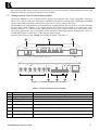
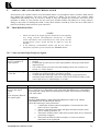
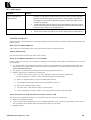
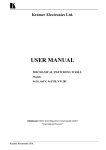
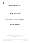
KRAMER ELECTRONICS, Ltd.
USER MANUAL
6X1 Switchers / Scanners
Models:
VS-16N
VS-16A
IMPORTANT: Before proceeding, please read paragraph entitled
"Unpacking and Contents"
KRAMER ELECTRONICS LTD.
P/N: 2900-002006
Table of Contents
Section
Name
Page
1
1.1
1.2
2
3
4
4.1
5
5.1
5.2
6
6.1
7
8
8.1
8.1.1
8.1.2
8.1.3
8.1.4
8.1.5
8.1.6
8.1.7
8.2
9
10
10.1
10.2
INTRODUCTION
A Word on Switchers
Factors Affecting Quality of Results
SPECIFICATIONS
HOW DO I GET STARTED?
UNPACKING AND CONTENTS
Optional Accessories
VS SERIES SWITCHERS/SCANNERS
Getting to Know Your VS-16N Switcher/Scanner
Getting to Know Your VS-16A Switcher/Scanner
INSTALLATION
Rack Mounting
CONNECTING TO VIDEO and AUDIO DEVICES
USING the VIDEO/AUDIO SWITCHERS/SCANNERS
Controlling the Switcher
Start/Stop Switch
Dwell Time Switch
Enable/Disable Switch
Self Address
UP and Down Switches
ENTER Switch
Remote Connectors (rear)
RS-485
TAKING CARE OF YOUR SWITCHER
TROUBLESHOOTING
Video and other High Frequency Signals
Audio Signal
Limited Warranty
2
2
2
3
3
3
4
5
5
6
7
7
7
7
7
7
7
7
8
8
8
8
8
9
9
9
10
10
List of Illustrations
Figure
1
2
VS-16N Front/Rear Panel Features
VS-16A Front/Rear Panel Features
5
6
List of Tables
Table
1
2
VS-16N Front/Rear Panel Features
VS-16A Front/Rear Panel Features
KRAMER ELECTRONICS LTD.
5
6
P/N: 2900-002006
1.
INTRODUCTION
Congratulations on your purchase of this Kramer Electronics switcher/scanner. Since 1981 Kramer has been
dedicated to the development and manufacture of high quality video/audio equipment. The Kramer line has
become an integral part of many of the best production and presentation facilities around the world. In recent
years, Kramer has redesigned and upgraded most of the line, making the best even better. Kramer’s line of
professional video/audio electronics is one of the most versatile and complete available, and is a true leader in
terms of quality, workmanship, price/performance ratio and innovation. In addition to the Kramer line of high
quality switchers, such as the one you have just purchased, Kramer also offers a full line of high quality
distribution amplifiers, processors, interfaces, controllers and computer-related products. This manual includes
configuration, operation and option information for the following products from the Kramer VS line of
switchers/scanner. All these VS switchers/scanners are similar in operation and features. The switchers/scanners
described in this manual are listed below:
VS-16N - 6x1 Video Switcher/Scanner
VS-16A - 6x1 Dual Wideband Switcher/Scanner
1.1 A Word on Switchers
Switchers route one or more signals to one or more users. They vary in the number of inputs, programming
capability, number of outputs, operating format (composite video, component, audio etc.) and switching method
(i.e., whether they switch during the vertical interval or not, whether they are electronic, RS232 or mechanically
controlled). A video/audio switcher usually switches between several sources (inputs) and one or more
acceptors (outputs). A switcher that allows several inputs to be connected to several outputs simultaneously is
called a Matrix Switcher. Switchers may be of the electronic or mechanical type. Most matrices are of the active
electronic type, with many crosspoints. Vertical Interval Switching, frequently used in video, ensures that the
transition from one video source to another is smooth and without interference. The mechanical switchers
described in this manual have full industrial specifications and are rack-mountable. The video/audio switchers
offer a simple and economic solution for every video/audio application. Due to very careful design the video
bandwidth is excellent.
1.2 Factors Affecting Quality of Results
The factors affecting the quality of results when signals are transmitted from a source to an acceptor are:
Connection cables
Sockets and connectors of
the sources and acceptors
Distance between sources
and acceptors
Interference from
neighboring electrical
appliances
KRAMER ELECTRONICS LTD.
Low quality cables are susceptible to interference; they degrade signal quality
due to poor matching and cause elevated noise levels. They should therefore be
of the best quality.
So often ignored, they should be of highest quality, since "Zero Ohm" connection
resistance is the objective. Sockets and connectors also must match the required
impedance (75ohm in video). Cheap, low quality connectors tend to rust, thus
causing breaks in the signal path.
Plays a major role in the final result. For long distances (over 15 meters) between
sources and acceptors, special measures should be taken in order to avoid cable
losses. These include using higher quality cables or adding line amplifiers.
These can have an adverse effect on signal quality. Balanced audio lines are less
prone to interference, but unbalanced audio should be installed far from any
mains power cables, electric motors, transmitters, etc. even when the cables are
shielded.
2
2.
3.
SPECIFICATIONS
VS-16N
VS-16A
Function
6x1 Video Switcher/Scanner
6x1 Dual Wideband
Switcher/Scanner
Inputs
6 video, 1Vpp / 75 ohms on
BNCs, 6 binding posts for
external control
6 dual signal sources- audio,
video or component, level and
impedance are source dependent,
on RCA connectors. 6 terminal
blocks for external remote
control.
Outputs
1 composite video, looping,
1 Vpp/75 Ω on a BNC.
1 dual signal - audio, video or
component, level and impedance
are acceptor dependent, on RCA
connectors.
Bandwidth
40 MHz. -3dB.
540 MHz. -3dB.
Differential Gain
0.9%.
0.02%.
Differential Phase
0.37 Deg.
0.02 Deg.
K-Factor
<0.05%.
<0.05%
S/N Ratio
>72 dB.
>72 dB
Crosstalk
<50 dB @ 5 MHz
<50 dB @ 5 MHz
Controls
Automatic, manual, RS-485, and Automatic, manual, RS-485 and
contact closure. Switching during remote contact closure.
Vertical Interval (derived from
source no. 1).
Dimensions
(W, D, H)
24.5cm x 18cm x 4.5cm
(9.6" x 7" x 1.8")
24.5cm x 18cm x 4.5cm
(9.6" x 7" x 1.8")
Weight
1. 5kg. (3.3lbs.) Approx.
1.3kg. (2.9lbs.) Approx.
HOW DO I GET STARTED?
The fastest way to get started is to take your time and do everything right the first time. Taking 15 minutes to
read the manual may save you a few hours later. You don’t even have to read the whole manual. At the
beginning of each section, you’ll find an overview of the section. If the section doesn’t apply to you, you don’t
have to spend your time reading it.
4.
UNPACKING AND CONTENTS
The items contained in your Kramer VS switcher/scanner package are listed below. Please save the original box
and packaging materials for possible future shipment.
Switcher/Scanner
User Manual
Kramer concise product catalog
4 rubber feet
Power Cord
For additional information regarding optional cables and additional accessories, contact your Kramer dealer.
KRAMER ELECTRONICS LTD.
3
4.1 Optional Accessories
The following accessories, which are available from Kramer, can enhance implementation of your switcher.
Rack Adapter - Used to adapt smaller machines to a standard 1U rack. One or more machines may be installed
on each adapter.
BNC "Y" Connector - Used for looping purposes and splits the incoming signal to enable connection of an
additional machine.
SP-11 - (Video/Audio Processor) can be serially connected between the video/audio source and the VS
switcher/scanner for video and audio control/correction. The machine may provide camera control and
luminance/white balance correction. The SP-11 is also capable of performing Composite to Y/C switching and
bi-directional Transcoding. The machine allows full control over the video signal: Video gain down to full fade,
log or linear Definition control, log or linear Contrast control, Color saturation control, Black Level control,
Red, Green and Blue controls and a Screen Splitter control for “before-after” comparison.
VM-1010 - (Video Distribution Amplifier) can be serially connected between the switcher/scanner and the
acceptors for video distribution. It is a full broadcast, state-of-the-art, and programmable video distribution
amplifier. The VM-1010 has two looping video inputs, each splitting to 5 outputs. The user may select 2x1:5 or
1:10 operation via front panel control switches. Several VM-1010 units may be chained through the looping
inputs. Output signals are (user selectable) DC or AC coupled for maximum flexibility.
VM-20ARII - (Programmable Video/Audio Distribution Amplifier) can be serially connected between the
switcher/scanner and the video/audio acceptors for video/audio distribution. It is a full bandwidth, state-of-theart, 1:20 Programmable video/audio distribution. The VM-20ARII splits a single video and audio input source
into twenty identical outputs with no discernible signal degradation. The VM-20ARII has four looping video and
audio (stereo) inputs and a user programmable mode of operation. The VM-20ARII can function as a 1:20,
2x1:10, 4x1:5 or 1:10+2x1:5 DA, and audio operation mode may be separated from video mode. Output signals
are DC or AC coupled (user selectable) for highest signal fidelity. Due to the extended bandwidth of the
machine it can be also used for video/graphics component distribution. The machine has video gain and EQ.
controls for 4 sets of 5 outputs, as well as audio level controls. The audio section may be programmed to
function as unbalanced stereo or balanced mono.
VIDEO TESTER - A unique, patented, indispensable tool for the video professional, the Video Tester is used
to test a video path leading to/from a switcher. By pressing only one touch switch it can trace missing signals,
distinguish between good and jittery (VCR sourced) signals, and identify the presence of good signals.
Whenever a video signal is missing, because of bad connections, cable breaks or faulty sources, the Video Tester
is all you need. No need for oscilloscopes, waveform monitors or a Vectorscope to trace and rectify such
common problems. Indispensable for fieldwork, the Tester checks for sync and odd/even data in the signal and
is not triggered by noise, hum or even by a 15kHz non-video source. The Video Tester is compact (not much
bigger than a cigarette box), housed in sturdy plastic housing with pocket clip and is operated by a 9Volt battery
for three continuous hours of operation (the full shelf life of the battery).
5.
VS SERIES SWITCHERS/SCANNERS
KRAMER ELECTRONICS LTD.
4
This section describes all the controls and connections of your switcher/scanner. Understanding the controls and
connections helps you realize the full power of your switcher.
5.1 Getting to Know Your VS-16N Switcher/Scanner
The Kramer VS-16N is a 6x1 scanning switcher designed for composite video signals using BNC connectors.
Inputs can be selected using the front panel in addition to the typical scanning mode. Bandwidth of 40 MHz
ensures transparent performance with common video sources such as cameras and VCRs.
The VS-16N can be programmed to scan automatically, skipping unused inputs if desired. It can be controlled
by front panel buttons, RS-485, or by simply shorting the relevant pin to ground on the back panel screw
terminal connector. It is ideal for many applications in retail stores, studios, showrooms, and in many CCTV
and security applications. Up to 15 machines can be cascaded to form larger systems including 12x1, 18x1, etc.
The VS-16N connects to other units via RS-485 and output looping.
Front/rear panel features of the VS-16N are described in Figure 1 and Table 1.
Figure 1: VS-16N Front/Rear Panel Features
Table 1: VS-16N Front/Rear Panel Features
No.
1
2
3
4
Feature
POWER
Programming Buttons
LED Display
INPUTS
Function
Power ON/Off Switch, illuminates when toggled
Controlling the functions of the machine
Showing machine status, and for programming
6 Video inputs on BNC connectors
5
OUT
Looping video output on a BNC connector
6
REMOTE
Dry contact remote control binding posts
7
RS-485
RS-485 control binding post
8
POWER SOCKET
A fused socket for connecting the mains power cord
KRAMER ELECTRONICS LTD.
5
5.2 Getting to Know Your VS-16A Switcher/Scanner
The Kramer VS-16A is a high performance two-channel 6x1 scanning switcher compatible with a wide variety
of signals including audio, video, and component video using dual RCA connectors. Inputs can be selected
manually in addition to the typical scanning mode. Exceptionally high bandwidth of 540MHz ensures
transparent performance. Input impedance depends on the source, and output impedance is established by the
display or recording device.
The VS-16A can be programmed to scan automatically, skipping unused inputs if desired. It can be
controlled by front panel buttons, RS-485, or by simply shorting the relevant pin to ground on the back panel
screw terminal connector. It is ideal for many applications in retail stores, studios, showrooms, and in many
CCTV and security applications. Up to 15 machines can be cascaded to form larger systems including 12x1,
18x1, etc. The VS-16A connects to other units via RS-485 and output looping.
Front/rear panel features of the VS-16A are described in Figure 2 and Table 2.
Figure 2: VS-16A Front/Rear Panel Features
Table 2: VS-16A Front/Rear Panel Features
No.
1
2
3
4
Feature
POWER
Programming Buttons
LED Display
INPUTS
Function
Power ON/Off Switch, illuminates when toggled
Controlling the functions of the machine
Showing machine status, and for programming
6 dual signal inputs on RCA connectors
5
OUT
Looping dual wideband signal outputs on a RCAs
6
REMOTE
Dry contact remote control binding posts
7
RS-485
RS-485 control binding post
8
POWER SOCKET
A fused socket for connecting the mains power cord
KRAMER ELECTRONICS LTD.
6
6.
INSTALLATION
6.1 Rack Mounting
The VS-16N and VS-16A switchers/scanners may be rack-mounted in a standard 19” (1U) EIA rack assembly
using an optional rack adapter. The switchers in this manual do not require any spacing above or below them for
ventilation.
7.
CONNECTING to VIDEO AND AUDIO DEVICES
1.
Connect from one to six sources (or dual signal sources) to the inputs on the rear panel of the VS-16N
(VS-16A) using recommended cables, taking care that all connections are correct.
2.
Connect a signal acceptor to the output sockets on the rear panel of the VS-16N or VS-16A. If your are
setting up a multi-switch system, (an 18x1 scanner system for example) all output connectors should be
connected in parallel using "T" or “Y” connectors, while the last switcher output is connected via the "T"
or “Y” connector to the previous switcher and to the video acceptor (monitor, VCR etc.)
3.
Connect, if necessary, 6 control wires to the "REMOTE" connectors on the rear panel of the machine.
Two additional ground connections are available, and both may be used.
4.
Connect three wires to the RS-485 connectors on the rear panel of the machine if RS-485 control or
system extension is needed. If a multi-switch system is being set-up, connect all the wires in parallel
between all switchers, e.g., A to A, B to B and G to G (Ground). If an external RS-485 controller is used,
it must be connected to this bank in a similar way.
5.
Connect the VS-16N or VS-16A to a power source and turn it on.
8.
USING the VIDEO /AUDIO SWITCHERS/SCANNERS
8.1
Controlling the Switcher
8.1.1
Start/Stop Switch
This switch changes the mode between Switcher and Scanner operation. In Scanner operation (automatic
switching) the decimal point on the lower right corner of the display will blink. In Switcher mode (manual) the
decimal point will be off. The machine will scan only inputs, which are ENABLED.
8.1.2
Dwell time Switch
This switch controls the dwell time when automatically switching. When the switch is pressed, the display will
blink, showing the preset dwell time. By pressing the UP or DOWN keys the time may be changed.
The dwell time may be set between 2 and 99 seconds. After reaching the required dwell time, press the ENTER
switch.
8.1.3
Enable/Disable Switch
This switch controls the enabled/disabled inputs while scanning. When the switch is pressed, the right display
will show the input number, while on the left display will show either the letter E (enabled) or D (disabled).
Toggling between modes E and D is done by pressing again this switch. Pressing the UP or DOWN key browses
all the inputs, showing their status. Changing the status is done by pressing the Enable/Disable switch. When
you finished programming the machine, press the ENTER switch.
KRAMER ELECTRONICS LTD.
7
8.1.4
Self Address
This switch controls the self address of the machine. When the machine works stand-alone, it's self address is 1.
When this key is pressed, the number shown on the display is the self-address of the machine.
The address may be changed by pressing the UP or DOWN keys. When finished, press the ENTER switch.
When operated as a stand-alone machine, the self-address must be set to 1. When more machines are connected
to the system, the numbers should be set in contiguity - e.g., 2, 3, 4 etc. The maximum number of machines that
can be chained is 15.
8.1.5
UP and DOWN Switches
These switches operate when the machine works as a Switcher (manual mode). Pressing the UP switch moves to
the next (higher numbered) input (moving from 4 to 5 for example). Pressing the DOWN switch does the
opposite operation. When you reached the required input, press the ENTER key, then this input will be routed to
the output. The switching in the VS-16N machine takes place during the Vertical Interval derived from source
number 1. The switching in the VS-16A takes place immediately when the button is touched or when an internal
or external command is given
8.1.6
ENTER Switch
Pressing this switch in Switcher mode will display input 1 on this machine. Pressing the UP switch will move to
the next input etc. To form the connection, press the ENTER key again.
The connected switchers recognize each other in the chain. For example, if you press the ENTER switch in
machine no. 2, and press twice the UP key, and then ENTER again, the display will show input 9 which
corresponds to input 3 on machine 2 (6+3=9).
8.1.7
Remote connectors (rear)
When a wire connected to one of the remote connectors is shorted to ground (available on two additional
connectors on the REMOTE bank) the corresponding input will be connected to the output.
8.2 RS-485
Via this connector bank, the machine can control or be controlled via RS-485 control. When several machines
are connected to form a large switcher/scanner setup, the RS-485 connectors should be all connected in parallel,
i.e., A to A, B to B and G to G (Ground). Please double check the wiring, as reversing a connection may damage
the machine or the controller.
KRAMER ELECTRONICS LTD.
8
9.
TAKING CARE of YOUR SWITCHER/SCANNER
Do not locate your switcher/scanner in an environment where it is susceptible to dust or moisture. Both of these
may damage the electronics, and cause erratic operation or failure. Do not locate your switcher where
temperature and humidity may be excessive. Doing so may also damage the electronics, and cause erratic
operation or failure of your switcher. Do not clean your switcher/scanner with abrasives or strong cleaners.
Doing so may remove or damage the finish, or may allow moisture to build up. Take care not to allow dust or
particles to build up inside unused or open connectors.
10. TROUBLESHOOTING
NOTES
1. Please note that if the output signal is disturbed or interrupted by
very strong external electromagnetic interference, it should
return and stabilize when such interference ends. If not, turn the
acceptor/source power switch off and on again to reset the
machine.
2. If the following recommended actions still do not result in
satisfactory operation, please consult your KRAMER Dealer.
10.1 Video and other High Frequency Signals
Problem
No signal at the output
device, regardless of
input selected.
Signal level is too high
or too dim.
Problem
Noise bars "roll" up or
down in the output
image
or:
Low Frequency Hum in
the output signal
Remedy
1. Confirm that your sources and output device are powered on and connected
properly.
2. Confirm that any other devices in the signal path have the proper input and/or
output selected.
3. Use a Video Tester to test the video path leading to/from your switcher (see
section 4.1 " Video Tester")
1. Verify that the signal line is well matched through 75ohm impedance; otherwise
it results in a signal level that is too high or too dim.
2. Confirm that the connecting cables are of high quality, properly built and
terminated with 75ohm BNC connectors. Check level controls located on your
source input device or output display or recorder.
Remedy
Hum bars (ground loop) are caused by a difference in the ground potential of any
two or more devices connected to your signal path. This difference is compensated
by passing that voltage difference through any available interconnection, including
your video cables.
WARNING!
DO NOT DISCONNECT THE GROUND FROM ANY PIECE OF VIDEO
EQUIPMENT IN YOUR SIGNAL PATH!
Check the following to remove hum bars:
3. Confirm that all interconnected equipment is connected to the same
phase of power, if possible.
4. Remove equipment connected to that phase that may introduce noise,
such as motors, generators, etc.
5. Disconnect all interconnect cables and reconnect them one at a time until
ground loop reappears.
6. Disconnect the affected cable and replace, or insert an isolation
transformer in the signal path.
KRAMER ELECTRONICS LTD.
9
10.2 Audio Signal
Problem
No audio at the output
device, regardless of
input selected
Remedy
1.
2.
Audio level is too low
1.
2.
Confirm that your sources and output device are turned on and connected
properly. Audio signals connected to the input of your switcher should be
properly wired to the output of your source. Audio signals connected to
the output of your switcher should be properly wired to the input of your
switcher or acceptor.
Confirm that any other switchers in the signal path have the proper input
and/or output selected. Pay special attention to input switchers that may be
built into your switchers or recording device.
Confirm that the connecting cables are of high quality and properly built.
Check level controls located on your source input device or output device.
LIMITED WARRANTY
Kramer Electronics (hereafter Kramer) warrants this product to be free from defects in material and workmanship under the
following terms.
HOW LONG IS THE WARRANTY
Labor and parts are warranted for three years from the date of the first customer purchase.
WHO IS PROTECTED
Only the first purchase customer may enforce this warranty.
WHAT IS COVERED AND WHAT IS NOT COVERED
Except as below, this warranty covers all defects in material or workmanship in this product. The following are not covered
by the warranty:
1) Any product which is not distributed by Kramer or which is not purchased from an authorized Kramer dealer. If you
are uncertain as to whether a dealer is authorized, please contact Kramer at one of the agents listed in the web site
www.kramerelectronics.com.
2) Any product, on which the serial number has been defaced, modified or removed.
3) Damage, deterioration or malfunction resulting from:
a) Accident, misuse, abuse, neglect, fire, water, lightning or other acts of nature, unauthorized
product modification, or failure to follow instructions supplied with the product.
b) Repair or attempted repair by anyone not authorized by Kramer.
c)
Any shipment of the product (claims must be presented to the carrier).
d) Removal or installation of the product.
e)
Any other cause, which does not relate to a product defect.
f)
Cartons, equipment enclosures, cables or accessories used in conjunction with the product.
WHAT WE WILL PAY FOR AND WHAT WE WILL NOT PAY FOR
We will pay labor and material expenses for covered items. We will not pay for the following:
1) Removal or installations charges.
2) Costs of initial technical adjustments (set-up), including adjustment of user controls or programming. These costs are
the responsibility of the Kramer dealer from whom the product was purchased.
3) Shipping charges.
KRAMER ELECTRONICS LTD.
10
HOW YOU CAN GET WARRANTY SERVICE
To obtain service on you product, you must take or ship it prepaid to any authorized Kramer service center.
Whenever warranty service is required, the original dated invoice (or a copy) must be presented as proof of warranty
coverage, and should be included in any shipment of the product. Please also include in any mailing a contact name,
company, address, and a description of the problem(s).
For the name of the nearest Kramer authorized service center, consult your authorized dealer.
LIMITATION OF IMPLIED WARRANTIES
All implied warranties, including warranties of merchantability and fitness for a particular purpose, are limited in duration
to the length of this warranty.
EXCLUSION OF DAMAGES
Kramer’s liability for any defective products is limited to the repair or replacement of the product at our option. Kramer
shall not be liable for:
Damage to other property caused by defects in this product, damages based upon inconvenience, loss of use of the product,
loss of time, commercial loss; or:
Any other damages, whether incidental, consequential or otherwise. Some countries may not allow limitations on how
long an implied warranty lasts and/or do not allow the exclusion or limitation of incidental or consequential damages, so
the above limitations and exclusions may not apply to you.
This warranty gives you specific legal rights, and you may also have other rights, which vary from place to place.
NOTE: All products returned to Kramer for service must have prior approval. This may be obtained from your dealer.
NOTICE
This equipment has been tested to determine compliance with the requirements of:
EN-50081:
EN-50082:
CFR-47
"Electromagnetic compatibility (EMC);
generic emission standard.
Part 1: Residential, commercial and light industry"
"Electromagnetic compatibility (EMC) generic immunity standard. Part 1:
Residential, commercial and light industry environment".
FCC Rules and Regulations:
Part 15- “Radio frequency devices:
Subpart B- Unintentional radiators
CAUTION
Servicing of the above mentioned machines is only allowed to a Kramer authorized technician or
Engineer. Any user who makes changes or modifications to the unit without the express approval of the
manufacturer will void user authority to operate the equipment.
Use the DC power supply (provided) to supply power to the machine and controllers.
Please use recommended interconnect cables to connect the machine to controllers and other components.
KRAMER ELECTRONICS LTD.
11
The list of Kramer distributors appears on our web site:
www.kramerelectronics.com
From the web site it is also possible to e-mail factory headquarters.
We welcome your questions, comments and feedback.
KRAMER ELECTRONICS, LTD.
3 Am VeOlamo Street. Jerusalem 95463, Israel Tel: (972-2)-654-4000. Fax: (972-2)-653-5369
E-mail: [email protected]