1
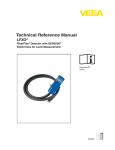
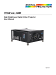
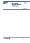
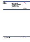
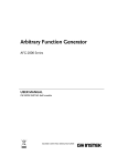
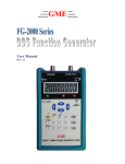
MX 9000 Process Monitor Operation and Programming Manual Table of Contents Safety Definitions and Information............................................................................................................... 5 Unpacking ..................................................................................................................................................... 5 Quick Guide................................................................................................................................................... 6 Connect to Sensor ..................................................................................................................................... 6 Connect to Power ..................................................................................................................................... 6 Basic Key Definitions ................................................................................................................................. 6 Programming and Data Entry ................................................................................................................... 6 Specifications ................................................................................................................................................ 7 Product Description ...................................................................................................................................... 8 Principle of Operation ............................................................................................................................... 8 Features .................................................................................................................................................... 8 Model Number Key ................................................................................................................................... 9 Technical Data............................................................................................................................................. 10 Power Supply ...................................................................................................................................... 10 Flow Sensor Power Output ................................................................................................................. 10 Frequency Inputs ................................................................................................................................ 10 Analog Output(s) 4-20 mA .................................................................................................................. 10 Relay Contact Ratings ......................................................................................................................... 10 Sensor / Pulse Inputs .............................................................................................................................. 12 Reset Input .............................................................................................................................................. 12 Analog Output(s) ..................................................................................................................................... 13 Frequency Output (option boards 1 and 2) ............................................................................................ 13 Relay Outputs.......................................................................................................................................... 13 Analog Input (option board 1) ................................................................................................................ 14 120/240 VAC Input (option board 2) ...................................................................................................... 15 Batch Controller Inputs (option board 3) ............................................................................................... 15 Run Mode Screens ...................................................................................................................................... 16 LOGO screen ........................................................................................................................................... 17 RATE screens ........................................................................................................................................... 17 2 MX 9000 User Manual, Rev. 2.1 3/5/2015 MX 9000 Process Monitor Operation and Programming Manual TOTAL / GRAND TOTAL screens .............................................................................................................. 17 STATUS screen ........................................................................................................................................ 18 RATIO AB/BA screens .............................................................................................................................. 18 RA/TA (RB/TB) screens............................................................................................................................ 18 ANALOG OUT screen ............................................................................................................................... 19 L1/L2 screen ............................................................................................................................................ 19 RA/RB screen .......................................................................................................................................... 20 TA/TB screen ........................................................................................................................................... 20 RATE A + B screen ............................................................................................................................... 20 RATE A - B screen ............................................................................................................................... 20 TOTAL (GrandTotal) A - B screen ........................................................................................................ 21 BATCH TOTAL screen............................................................................................................................. 21 Control Functions ........................................................................................................................................ 22 Programming .............................................................................................................................................. 22 Entering programming mode.................................................................................................................. 22 Changing values and making selections ................................................................................................. 22 RATE, TOTAL and GRAND TOTAL scaling ................................................................................................ 23 K-factor (scaling factor)....................................................................................................................... 23 RATE unit ............................................................................................................................................. 23 RATE time base ................................................................................................................................... 24 TOTAL units ......................................................................................................................................... 24 Analog output scaling ............................................................................................................................. 25 Fixed output source ............................................................................................................................ 26 RATE A (or B) source ........................................................................................................................... 26 TOTAL source ...................................................................................................................................... 27 GRAND TOTAL source ......................................................................................................................... 27 LIMIT / Pulse output programming ........................................................................................................ 28 Limit 1 & Limit 2 .................................................................................................................................. 28 Frequency output programming......................................................................................................... 30 Gate Time filter ....................................................................................................................................... 30 3 MX 9000 User Manual, Rev. 2.1 3/5/2015 MX 9000 Process Monitor Operation and Programming Manual Linearizer programming.......................................................................................................................... 31 Quadrature Signal programming ............................................................................................................ 32 System Settings programming ................................................................................................................ 32 Calibrating Analog Output .......................................................................................................................... 33 I/O Manual Adjustment .............................................................................................................................. 34 Analog output adjustment ...................................................................................................................... 34 Fine mA adjustment ............................................................................................................................ 35 Coarse mA adjustment ....................................................................................................................... 35 Frequency adjustment ............................................................................................................................ 35 Fine limit output adjustment .............................................................................................................. 35 Coarse limit output adjustment .......................................................................................................... 36 ON/OFF Limit output adjustment ....................................................................................................... 36 Monitor external reset input .................................................................................................................. 36 Ratio AB / BA programming .................................................................................................................... 37 IDEAL AB/IDEAL BA ............................................................................................................................. 37 WARNING AB/WARNING BA ............................................................................................................... 37 ALARM AB/ALARM BA ........................................................................................................................ 38 TARGET NBR ........................................................................................................................................ 38 BATCH TOTAL Programming ................................................................................................................... 38 Batch Controller Programming ................................................................................................................... 40 Restoring Factory Defaults.......................................................................................................................... 43 Appendix A – Physical Dimensions ............................................................................................................. 44 Appendix B – Default Variable Values ........................................................................................................ 47 Appendix C – Revision History .................................................................................................................... 48 Limited Warranty ........................................................................................................................................ 49 4 MX 9000 User Manual, Rev. 2.1 3/5/2015 MX 9000 Process Monitor Operation and Programming Manual Safety Definitions and Information Do not attempt to install or use your AW Gear Meters product until you have read the safety instructions in this section. Save this manual and keep it in an easily accessible place. Warning! Warning means that failure to follow this safety statement may result in extensive product damage, serious personal injury, or death. Caution Caution means that failure to follow this safety statement may result in minor or moderate personal injury, property or equipment damage. Notice Notice is a statement that informs about installation, operation, maintenance, performance issues, or general tips that are important but do not create a hazard or safety concern. Unpacking Separate the MX 9000 Flow Monitor from packaging materials and check for any visual signs of damage. If you determine there are damages caused by shipping, file a claim with the shipping company. If the flow monitor appears to have been improperly assembled or does not operate properly, return it for replacement or repair (see Limited Warranty information at the end of this manual). Caution Before connecting, programming, or operating the MX 9000 Flow Monitor, read this manual. 5 MX 9000 User Manual, Rev. 2.1 3/5/2015 MX 9000 Process Monitor Operation and Programming Manual Quick Guide Caution As with any precision-engineered device, always operate the MX 9000 in accordance with the manufacturer’s instructions. Connect to Sensor You will connect three wires from the sensor(s) to the back of the MX 9000: An electrical power wire a signal wire, and a ground wire Notice Dual input models use two sensors (terminals for sensor 2). Insert the stripped end of the red wire into lower terminal #3 (6) and use a screwdriver to secure. Insert the stripped end of the white wire into lower terminal #4 (7) and the stripped end of the black wire into lower terminal #5 (8). Use a screwdriver (push / release) to secure these wires with the spring terminals. Connect to Power Insert the leads from the 120VAC adaptor into terminals 1 & 2 of the lower block. Plug the adaptor into a wall receptacle. If you are supplying power from a DC source, insert the positive lead into terminal #1 and the negative lead to terminal #2. DC input should be from 18 to 24 volts. Basic Key Definitions The MX 9000 has four keys for data input and programming: DOWN / NO UP / YES SELECT / RESET ENTER / EXIT Use the SELECT key to move the cursor to the digit you would like to change or reset the total values, use the UP and DOWN keys to change between screens or increase or decrease the value as desired, and use the ENTER key to enter the information. Programming and Data Entry Upon power up, move to the screen that you wish to adjust. Hold the ENTER key in for 3 seconds and screen will change to programming mode. Follow screen prompts. When in programming mode, numerical values are underlined or you are prompted to answer YES or NO. Use the SELECT key to move between characters then the DOWN / UP keys to change. Press ENTER to store the value. Use YES / NO to enter other setup functions and EXIT when completed. See Programming the MX 9000 beginning on page 21 for complete details. 6 MX 9000 User Manual, Rev. 2.1 3/5/2015 MX 9000 Process Monitor Operation and Programming Manual Specifications Power Requirements: 16 VAC / 18-24 VDC / 200mA Sensor/Monitor Input Ratings: o Frequency Input Range: 0.3-4,500 Hz o High Level Pulse Input: 5VPEAK Min., 24VPEAK Max. Sensor Supply Voltage: 15 VDC @ 50mA Max. Analog Output(s) 4-20 mA: 16-bit isolated loop powered 2-wire output; 9-24 VDC; max. load impedance = 500 Ohm @ 24V; max. load impedance = 250 Ohm @ 12V; main output HART enabled (option) Opto-Isolated Open-Collector Frequency Output (optional): 5-30 VDC, 40 mA Max. (minimum load impedance required = 600 Ohm @ 24 VDC) Opto-Isolated Reset Input: 12-24 VDC Input, 3.3Kohm Impedance Relay Outputs (optional): 2A @ 100VDC, 1A @ 250VAC MAX. Temperature Ratings: -4 to 140°F (-20 to 60°C) ambient; 185°F (85°C) max. Enclosure: DIN #43700, panel mount, plastic Height = 67mm/2.6 inches; height w/ flange 69mm/2.8 inches Width = 90mm/3.53 inches; width w/ flange = 97mm/3.8 inches Depth = 132mm/5.2 inches; depth w/ flange = 139mm/5.5 inches Connection: spring loaded terminal strips Display update rate: 250 milliseconds (4 times per second) Analog output update rate: 20 milliseconds (if Gate Time filter off) AC Power board (optional): 120 / 240 VAC / 0.5A fuse Analog Input (optional): 4-20 mA, 0-5 VDC, 0-10 VDC USB connector: Type B 7 MX 9000 User Manual, Rev. 2.1 3/5/2015 MX 9000 Process Monitor Operation and Programming Manual Product Description The MX 9000 Flow Monitor is a versatile, multi-functional device that helps you track rate, flow, limit, ratio, and other variables. The unit’s multicolor back-lighted LCD display is easy-to-read with up to 22 different display modes available, depending on model. The standard unit is one channel, but the optional two-channel version allows you to monitor dual flows and display them in a number of ways: separately, as a sum (for example in total material use), as a difference (as in fuel consumption), or as a ratio of product A/product B. You can also use the MX 9000 to detect bi-directional flow when A and B channel signals are available from a single flow meter. Other capabilities include the capacity to monitor data and program the unit remotely. Four model variations give the MX 9000 the capability of performing limit, warning and alarm duties and batching. Principle of Operation After first making connections to the power source and to flow transmitter input and output, you can choose up to 22 display modes. These include rates, totals, ratios, limits and others, based on the model purchased. Then input k- factor values, the required engineering units, gate times, limits, etc. A 20 point linearizer is built-in for added display accuracy. You may also program other values such as warning/alarm limits and ratios, depending on model. Features Two programmable Form C Relay outputs (optional) Up to two assignable 4-20 mA output (optional) Large, easy-to-read LCD display Multicolor LCD backlight to indicate out-of-limit or error conditions Single or dual channel models Ratio monitor version available On screen prompts with entry error checks simplify programming Batch controller version 8 MX 9000 User Manual, Rev. 2.1 3/5/2015 MX 9000 Process Monitor Operation and Programming Manual Model Number Key MX9- A B - C D Communication protocol No additional options X 1 2 3 4 X S D R B Option boards 4-20mA output 2, Frequency out, Analog in, 2 relay out 120/240VAC supply, 4-20mA out, Frequency out, 2 relay out +15 VDC out, 5 external inputs (batch controller only), 2 relay out Output options 4-20mA output 1 No outputs Main board options Single channel flow/total Dual channel flow/total Ratio monitor Batch controller 9 MX 9000 User Manual, Rev. 2.1 3/5/2015 MX 9000 Process Monitor Operation and Programming Manual Technical Data Minimum Power Supply Requirements 16 VAC/250mA with supplied 110 VAC transformer, or 18-24 VDC/250mA. (customer supplied direct current) 120/240 VAC with option board 2 Flow Sensor Power Output (2) @ 15 VDC/50 mA. each Frequency Inputs 0-4.5 KHz, sine, square or saw-tooth; 5 volts minimum amplitude; 3.3K Ohm impedance Analog Output(s) 4-20 mA external-powered loop output into a maximum 500 Ohm load impedance with 24 volt supply Relay Contact Ratings Maximum Switched Power DC: 60W AC: 125VA DC: 30W AC: 60VA 100VDC, 250VAC 2A/DC, 1A/AC DC: 30V, 2A AC: 125V, 1A DC: 30V, 1A AC: 125V, 0.3A Resistive Load Inductive Load Maximum Switched Voltage Maximum Switched Current Rated Load Resistive Load Inductive Load Figure 1: Relay Contact Ratings NOTE: Maximum wire gauge 16 AWG LOWER TERMINAL BLOCK CONNECTIONS: Pin 1: Pin 2: Pin 3: Pin 4: Pin 5: Pin 6: Pin 7: Pin 8: Pin 9: Pin 10: Pin 11: Pin 12: (+) 18-24 VDC Supply Voltage / 16 VAC Input (-) 18-24 VDC Supply Voltage Ground / 16 VAC Input (+) Sensor 1 Supply Voltage 15 VDC 25 mA MAX Sensor 1 Signal Input (-) Sensor 1 Supply / Signal Common (+) Sensor 2 Supply Voltage 15 VDC 25 mA MAX Sensor 2 Signal Input Housing Ground (-) Sensor 2 Supply / Signal Common (+) External Reset Input (-) External Reset Input (+) mA Loop 1 Output (-) mA Loop 1 Output 10 MX 9000 User Manual, Rev. 2.1 3/5/2015 MX 9000 Process Monitor Operation and Programming Manual UPPER TERMINAL BLOCK CONNECTIONS (Option Board 1): Pin 1: Pin 2: Pin 3: Pin 4: Pin 5: Pin 6: Pin 7: Pin 8: Pin 9: Pin 10: Pin 11: Pin 12: Limit 2 Relay NC Limit 2 Relay NO Limit 2 Relay COM Limit 1 Relay NC Limit 1 Relay NO Limit 1 Relay COM (+) Analog Input (-) Analog Input (+) Frequency Out (-) Frequency Out (+) mA Loop 2 Output (-) mA Loop 2 Output UPPER TERMINAL BLOCK CONNECTIONS (Option Board 2): Pin 1: Pin 2: Pin 3: Pin 4: Pin 5: Pin 6: Pin 7: Pin 8: Pin 9: Pin 10: Pin 11: Pin 12: Limit 2 Relay NC Limit 2 Relay NO Limit 2 Relay COM Limit 1 Relay NC Limit 1 Relay NO Limit 1 Relay COM (+) mA Loop 2 Output (-) mA Loop 2 Output (+) Frequency Out (-) Frequency Out 120/240 VAC Input Common 120/240 VAC Input Line UPPER TERMINAL BLOCK CONNECTIONS (Option Board 3): Pin 1: Pin 2: Pin 3: Pin 4: Pin 5: Pin 6: Pin 7: Pin 8: Pin 9: Pin 10: Pin 11: Pin 12: Limit 2 Relay NC Limit 2 Relay NO Limit 2 Relay COM Limit 1 Relay NC Limit 1 Relay NO Limit 1 Relay COM +15 VDC (for remote switch select) Mode Change Input Batch Select Input Batch Reset Input Start / Stop Input Program / Run Input 11 MX 9000 User Manual, Rev. 2.1 3/5/2015 MX 9000 Process Monitor Operation and Programming Manual Sensor / Pulse Inputs Pulse inputs are opto isolated and come referenced to signal ground. Regulated +15 VDC at 50mA max is available for powering each sensor. Inputs can also be isolated from the control power by cutting CT1 or CT2 with a sharp knife but then the internal +15 VDC supply is not available. Minimum input voltage is 5 VDC peak for pulses. Figure 2: Sensor / Pulse Inputs Reset Input Opto-isolated external reset input will trigger the MX 9000 to reset the totalizer(s) when the input sees a momentary transition from low (ground) to high (near supply). Reset input can be isolated from internal ground by cutting CT3 with a sharp knife. Figure 3: Reset Input 12 MX 9000 User Manual, Rev. 2.1 3/5/2015 MX 9000 Process Monitor Operation and Programming Manual Analog Output(s) The isolated 16-bit 4-20mA output(s) can be wired for use with Loop powered inputs or for ground referenced inputs. The analog signal has an internal LED in series which varies in intensity as the mA signal varies. This can be used for troubleshooting purposes. When using the analog signal with inputs used with loop powered signals, it is important to note that the MX 9000 requires an external power supply to power the loop as shown below. Figure 4: Analog Outputs Frequency Output (option boards 1 and 2) An opto-isolated NPN open-collector output can sink or source depending on connection. Attention must be paid to polarity of connections. Limit circuit current to 50 mA and 30 VDC for this circuit. Figure 5: Frequency Output 13 MX 9000 User Manual, Rev. 2.1 3/5/2015 MX 9000 Process Monitor Operation and Programming Manual Relay Outputs Two form C relay outputs are available on option boards 1 and 2. They are programmed by the limit screens as to the function of each. See Relay Contact Ratings on page 10 for limits. Figure 6: Relay Outputs Analog Input (option board 1) The analog input is available on option board 1. It can be configured for either a 4-20 mA input or a 0-5 or 0-10 VDC input. The input is referenced to the system common. Programming of the input is done using JP1. For 4-20 mA, use jumper pins 1&3 and 2&4. For 0-5 VDC, use jumper pins 3&5 and 4&6. For 0-10 VDC, use jumper pins 3&5 only. Pins are identified on the printed circuit board. Remove back cover to access. Figure 7: Analog Input 14 MX 9000 User Manual, Rev. 2.1 3/5/2015 MX 9000 Process Monitor Operation and Programming Manual 120/240 VAC Input (option board 2) The line voltage input is available on option board 2. It can be configured for 120 or 240 volt input using jumper pins 1. For 120 volt input jumper both sets of outside pins (see decal on board). For 240 volt input jumper only the center two pins (see decal). NOTE – board is factory set for 120 volt input. Figure 8: 120/240 VAC Input Batch Controller Inputs (option board 3) Five inputs are available for remote control of the batch process. You must have ordered the batch model to access these inputs (MX9-B). A 15 VDC output is provided as a supply for the inputs. Program / Run uses a maintained contact (switch), and the other inputs require momentary signals. Figure 9: Batch Controller Inputs 15 MX 9000 User Manual, Rev. 2.1 3/5/2015 MX 9000 Process Monitor Operation and Programming Manual Run Mode Screens The run mode screens, as shown below, can be accessed by using the UP and DN buttons. Info screen shows critical information on MX 9000 model number, serial number and firmware version. Notice Please have this information available when calling for technical support! RATE screen A shows active flow rate information in programmed engineering units RATE screen B shows active flow rate information in programmed engineering units TOTAL screen A shows totalized volume in programmed engineering units TOTAL screen B shows totalized volume in programmed engineering units STATUS screen shows data summary. Flow and total are in un-scaled units of Hertz for flow and Pulses for total. RATIO A/B screen displays rate ratio in % between A&B flows RATIO B/A screen displays rate ratio in % between B&A flows RT/TO screen A shows both the flow rate and total values in programmed engineering units RT/TO screen B shows both the flow rate and total values in programmed engineering units ANALOG OUT screen shows the mA value the MX 9000 is outputting Limits screen shows status of current relay outputs Rate A&B screen shows both rates on one screen Total A&B screen shows both running totals on one screen Rate A plus B screen shows mathematical total of both rates Rate A minus B screen shows differential between rate A and rate B Total / Grand Total A minus B screen shows differential between total A and B Batch total screen shows current total and relay status Direction screen shows flow direction when programmed for a dual sensor (quadrature) input 16 MX 9000 User Manual, Rev. 2.1 3/5/2015 MX 9000 Process Monitor Operation and Programming Manual LOGO screen MX 9000 S/N 0000000 Software Version 1.0.0 HART SW Version 1.0.0 The LOGO screen shows 3 or 4 lines of important data for the display unit which is needed if contacting the factory for support issues. 1. Line 1 shows the basic model name 2. Line 2 shows the unique serial number of the unit. 3. Line 3 shows the firmware version of the unit 4. Line 4 shows the firmware version of the HART protocol. NOTE: Line 4 will only show if the unit was purchased with the HART protocol option Pushing the SELECT button on the LOGO screen will show the actual model number of the MX 9000. As the features vary with the model, please make a note of this while reading through this manual. RATE screens RATE A(B) GPM 600.00 Figure 1: RATE screen The RATE screen displays the flow rate of A or B in the programmed engineering units. If the linearizer is active, ‘LN’ shows in lower left corner. If the Gate Time filter is active, ‘GT’ shows in lower right corner. TOTAL / GRAND TOTAL screens TOTAL A(B) GAL 6000 Figure 2: TOTAL screen The TOTAL screen displays the flow total of A or B in programmed engineering units. Pressing the RESET button resets the value back to zero (0). The Total can also be reset remotely by connecting a momentary voltage to the external RESET input. GRAND TOTAL A(B) 6000 GAL 17 MX 9000 User Manual, Rev. 2.1 3/5/2015 MX 9000 Process Monitor Operation and Programming Manual The GRAND TOTAL screen can be accessed using the ENTER button from the TOTAL screen. To reset this total pressing the RESET button will request the user to enter a password at this point. Use the UP – DOWN – SELECT buttons to enter the password code of “53126”. Then press the RESET button which will reset the grand total value back to zero (0). Note that both grand totals must be reset independent of one another. STATUS screen STATUS L1 OFF L2 OFF RTA 100.14 TOA 15400 RTB 150.32 TOB 03561 ANLG 04.00 mA The STATUS screen is a raw data display of the current major properties of the monitor. The rates are shown as Hz, total in pulses, limits as on or off and current loop output (main loop only) in programmed mA DC. NOTE: The Gate Time filter and linearizer, if active, do not affect the flow rate value in the STATUS screen. This is the raw incoming frequency. The mA shown is not a direct reading of the loop current if there are other problems outside of the controller such as a broken wire or defective loop power source. NOTE: Because the mA value is an actual signal output, it is affected by the Gate Time and linearizer, if activated. You can also access screen control programming from this screen by pushing and holding the ENTER button for 3 seconds. Use the UP – DOWN – SELECT buttons to enter the password code of “53126”. This password cannot be changed. See the advanced programming section for further information on this process. RATIO A/B (B/A) screens RATIO AB (BA) 1.00 The ratio A/B (B/A) screens show the mathematical relationship of the two flows of dual channel units. NOTE: the units of both flows must be the same for this display to work properly. RA, TA (RB, TB) screens RA TA 1234.56 123456.00 GPM GAL 18 MX 9000 User Manual, Rev. 2.1 3/5/2015 MX 9000 Process Monitor Operation and Programming Manual The dual rate / total screen are a convenient way of showing both the flow and total at the same time. Pressing the RESET button resets the total value back to zero (0). If the gate time or linearizer are active those will also be indicated by a LN in the lower left or GT in the lower right of the display. By pushing the ENTER key you can change the total displayed to grand total and will be indicated by a GA or GB in front of the total. ANALOG OUT screen ANALOG OUT 04.00 RA mA LN GT ANALOG OUT screen shows the mA value the MX 9000 is outputting. The 2 letters in the upper right corner indicate what variable the mA output has been assigned to represent. 1. FX = Fixed mA output 2. RA = mA output is scaled to represent the RATE value 3. TO = mA output is scaled to represent the TOTAL value 4. GR = mA output is scaled to represent the GRAND TOTAL value If the linearizer is active, ‘LN’ shows in lower left corner. If the Gate Time filter is active, ‘GT’ shows in lower right corner. L1/L2 screen L1 L2 OFF OFF OFF OFF The L1/L2 screen shows what the Limits are programmed to represent and the state of the output. The first line of each limit represents what the Limit is programmed for: 1. OFF – Limit output has been turned off. 2. Rate – The Limit output will change state when the flow rate reaches the programmed value 3. Total – The Limit output will change when the TOTAL reaches the programmed value 4. Grand Total - The Limit output will change when the GRAND TOTAL reaches the programmed value The second line of each limit represents the actual state of the output pin(s) 19 MX 9000 User Manual, Rev. 2.1 3/5/2015 MX 9000 Process Monitor Operation and Programming Manual RA/RB screen RA RB 34.00 56.00 GPM GPM The rate A and B screen is another dual combination screen that provides visibility to both rates at the same time. If the gate time or linearizer are active those will also be indicated by a LN in the lower left or GT in the lower right of the display. TA/TB screen TA TB 500.00 800.00 GAL GAL The total A and B screen is another dual combination screen that provides visibility to both totals at the same time. If the gate time or linearizer are active those will also be indicated by a LN in the lower left or GT in the lower right of the display. By pushing the ENTER key you can change the totals displayed to grand totals and will be indicated by a GA and GB in front of the totals. RATE A + B screen RATE A + B 600.00 GPM The rate A + B screen shows the mathematical sum of the two flows of dual channel units. If the gate time or linearizer are active those will also be indicated by a LN in the lower left or GT in the lower right of the display. NOTE: the units of both flows must be the same for this display to work properly. You will receive a warning message if you do not have them matching. RATE A - B screen RATE A - B 0.16 GPM 20 MX 9000 User Manual, Rev. 2.1 3/5/2015 MX 9000 Process Monitor Operation and Programming Manual The rate A - B screen shows the mathematical difference of the two flows of dual channel units. If the gate time or linearizer are active those will also be indicated by a LN in the lower left or GT in the lower right of the display. NOTE: the units of both flows must be the same for this display to work properly. TOTAL (GrandTotal) A - B screen TOTAL A - B + 450.00 GPM The total A - B screen shows the mathematical difference of the two totals of dual channel units. For A total being greater than B, a plus (+) sign will be displayed. If total B is greater than A, a minus (-) sign will be displayed. Pushing the ENTER key will change to the grand total screen. If the gate time or linearizer are active those will also be indicated by a LN in the lower left or GT in the lower right of the display. NOTE: the units of both flows must be the same for this display to work properly. BATCH TOTAL screen BATCH TOTAL 352000.00 S1 1000.0 S2 GAL 2000.0 The batch total screen will display the A channel total along with values for S1 and S2 (option board 3 is required for this feature). The batch function when enabled will turn on relay 1 and 2 when set points 1 and 2 are reached. Hold the ENTER key in for 5 seconds then you will be taken to the S1 set point screen. Enter the value to trigger relay 1 using the UP – DOWN – SELECT buttons. The screen will also turn to blue indicating that set point 1 is being set. Push ENTER to change to the S2 set point screen. Again enter the value to trigger relay 2 using the UP – DOWN – SELECT buttons. When operating, the screen will turn blue when set point 1 is reached and relay 1 is activated. When set point 2 is reached relay 2 is activated and the screen is turned red. 21 MX 9000 User Manual, Rev. 2.1 3/5/2015 MX 9000 Process Monitor Operation and Programming Manual Control Functions There are 4 dual function buttons located below the display to scroll through the screens or make changes in programming screens. The main functions are DOWN – UP – SELECT – ENTER. The alternate functions are NO – YES – SELECT – EXIT. Push the correct buttons as prompted on the screen when in programming mode. Programming Entering programming mode The MX 9000 main programming menus can be accessed from 3 of the run mode screens; [RATE], [ANALOG OUT] and limit [L1/L2] screens. To enter the programming menu from these screens, press and hold the ENTER button for 3 seconds until one of the programming screens appears. The programming menu will show the screen relevant to the run mode screen from which the programming menu was entered. Use the buttons as shown below to navigate through the screens. When exiting the programming menu, the MX 9000 will always return to the run mode screen from which the programming menu was entered. RUN Mode menu ENTER Hold 3 seconds Rate / Total Scaling? Analog Programming? Limits Programming? No Yes Exit No Yes Exit No Yes Exit YES EXIT Analog Menu Run Mode YES EXIT Limit Menu Run Mode YES EXIT Rate / Total Menu Run Mode Gate Time Programming? NO YES EXIT Linearizer Programming? NO YES EXIT Quadrature Signal Programming? NO YES EXIT YES EXIT Gate Time Menu Run Menu YES EXIT Linearizer Menu Run Menu YES EXIT Quadrature Menu Run Menu System Settings NO YES EXIT YES EXIT System Settings Menu Figure 10: Programming Mode Changing Values and Making Selections When in a programming screen which requires a value to be changed, the active character is indicated by an underscore. To increment the value use the UP button and to decrease the value use the DN button. The character value will wrap around when reaching either 9 or 0. 22 MX 9000 User Manual, Rev. 2.1 3/5/2015 MX 9000 Process Monitor Operation and Programming Manual Once a character has been changed press the SELECT button to move to the next character to the right. If at the right most character, pressing SELECT will bring the cursor back to the left most character. If a value has a decimal point whose position can be changed, press the SELECT button until the underscore is under the decimal point. Press the DOWN button to move the decimal point to the left and press the UP button to move the decimal point to the right. NOTE: Not all programming screens allow the decimal point location to be changed such as any milliamp value. Once a variable has been changed to the desired value, press the ENTER button to accept the value and move to the next screen or programming value. If an incorrect value is programmed, a warning or error screen will appear. Press any button to exit a warning screen, but you must correct an error before moving on. RATE, TOTAL and GRAND TOTAL Scaling Rate / Total Scaling? NO YES EXIT Enter K-Factor A in Pulses Per Gallon 123456.789 Select Rate A Units > GAL Select TOTAL A Units GAL Select Rate A Time Bas > Minutes Enter K-Factor B in Pulses Per Gallon 123456.789 Select Rate B Units > GAL Select TOTAL B Units Analog Menu GAL Select Rate A Time Bas > Minutes Figure 11: Rate, Total and Grand Total Scaling K-factor (scaling factor) The MX 9000 uses one K-factor for each channel for scaling displays. This value is always entered in units of Pulses per Gallon. Once the rate and total units are selected, the MX 9000 uses internal calculations to automatically correct the displayed values to match the user selected units. When the correct K-factor value has been programmed, press ENTER to continue. RATE unit Use the UP and DOWN buttons to scroll through the available units to scale the RATE screen. The available units are: GAL (US gallons) ML (Milliliters) LIT (Liters) M3 (Cubic meters) CC (Cubic centimeters) OZ (Liquid ounces) BBL (Barrels) PUL (Pulses) Once the desired unit is showing, press ENTER to continue. 23 MX 9000 User Manual, Rev. 2.1 3/5/2015 MX 9000 Process Monitor Operation and Programming Manual RATE time base Use the UP or DOWN buttons to select the time base to use in conjunction with the previously selected RATE units to define the flow rate unit. The available time units are: Seconds Minutes Hours Days When the correct time base is showing, press ENTER to continue. Notice NOTE: If the rate unit & time base are selected as PUL & Seconds, the RATE screen will show the unit as Hz, NOT PUL/SEC. TOTAL units Use the UP and DOWN buttons to scroll through the available units to scale the TOTAL and GRAND TOTAL screens. The available units are: GAL (US gallons) LIT (Liters) CC (Cubic centimeters) BBL (Barrels) ML (Milliliters) M3 (Cubic meters) OZ (Liquid ounces) PUL (Pulses) The Rate and Total units do not have to be the same. Once the desired unit is showing, pressing ENTER completes the scaling programming for channel A. Repeat the above to program channel B. When done, you will be at the Analog programming menu. 24 MX 9000 User Manual, Rev. 2.1 3/5/2015 MX 9000 Process Monitor Operation and Programming Manual Analog output scaling Analog Programming? NO YES EXIT Select Analog Source RATE A Sub menus Select Analog Source TOTAL A Select Analog Source Grand Total A Select Analog Source RATE B Select Analog Source TOTAL B Select Analog Source Grand Total B Select Analog Source Fixed Output Figure 12: Analog Output Scaling When entering the Analog programming menu, the first screen asks to select the Analog Source, or what the analog output value is to represent. There are 7 choices: RATE A TOTAL A Grand Total A Rate B TOTAL B Grand Total B Fixed Output Using the UP and DOWN buttons scrolls through the 7 choices that the mA output can represent: a fixed mA output value, input flow rate A or B, the totalizer value A or B, or the grand totalizer value A or B. Press ENTER when desired choice is showing. 25 MX 9000 User Manual, Rev. 2.1 3/5/2015 MX 9000 Process Monitor Operation and Programming Manual Fixed output source Fixed mA Output Limits Programming menu 04.00 mA Figure 13: Fixed Output Source This option allows the user to select a constant mA value the MX 9000 will output regardless of any changing values. A constant mA signal could be used as an external indicator showing if the MX 9000 is on. Allowable values are from 2mA to 20mA. RATE A (or B) source Min Flow Rate 0000000.00 GPM Min Flow mA 04.00 mA MAX Flow Rate 0000100.00 GPM Max Flow mA 20.00 mA Zero Flow mA Limits Programming menu 04.00 SEE NOTE BELOW Figure 14: Rate A or B Source RATE source allows the user to configure the mA output to represent the flow rate value. The analog output span can be scaled for either zero to max flow or a non-zero flow to max flow. If the flow rate goes above the programmed maximum flow rate, the analog output will continue to increase, up to a maximum of 22mA. This is useful for system fault detection. Min Flow Rate Enter the minimum user flow rate. This can be a non-zero value, such as the lowest application flow rate if the equipment monitoring the mA signal can be programmed as such. It can also be entered as zero, but in this case it will affect the accuracy of the mA reading vs flow accuracy. If a non-zero value is entered, the user will also be asked to enter a mA value to represent zero flow. Min Flow mA Enter the mA to represent the above entered minimum flow rate. Value must be equal to or greater than 2mA. Max Flow Rate Enter the maximum flow rate to monitor. Max Flow mA Enter the mA value to represent the above entered maximum flow rate value. 20mA is the maximum allowable value. Zero Flow mA This screen only shows if the Min Flow Rate was programmed as a non-zero value. Enter the mA value to represent zero flow. Lowest value allowable is 2mA (cannot be greater than the Min Flow mA value). 26 MX 9000 User Manual, Rev. 2.1 3/5/2015 MX 9000 Process Monitor Operation and Programming Manual TOTAL source Zero Total mA 04.00 mA MAX Total Value 0001000.00 GAL Max Total mA 20.00 mA Limits Programming menu Figure 15: Total Source TOTAL source allows the user to configure the mA output to represent the Totalizer value. If the totalizer value goes above the programmed maximum total value, the analog output will continue to increase, up to a maximum of 22mA. This is useful for system fault detection. Zero Total mA Enter the mA value to represent a zero totalizer value. Minimum allowable value is 2mA. Max Total Value Enter the maximum totalizer value to monitor. Max Total mA Enter the mA to represent the above entered maximum totalizer value. 20mA is the maximum allowable value. GRAND TOTAL source Zero Grand Total mA 04.00 mA MAX Grand Total Value 0001000.00 GAL Max Grand Total mA 20.00 mA Limits Programming menu Figure 16: Grand Total Source GRAND TOTAL source allows the user to configure the mA output to represent the Grand Total value. If the Grand Total value goes above the programmed maximum Grand Total value, the analog output will continue to increase, up to a maximum of 22mA. This is useful for system fault detection. Zero Grand Total mA Enter the mA value to represent a zero Grand Total value. Minimum allowable value is 2mA. Max Grand Total Value Enter the maximum Grand Total value to monitor. Max Total mA Enter the mA to represent the above entered maximum totalizer value. 20mA is the maximum allowable value. 27 MX 9000 User Manual, Rev. 2.1 3/5/2015 MX 9000 Process Monitor Operation and Programming Manual LIMIT / Pulse output programming Select Limit > Limit 1 Select Limit Type OFF Figure 17: Limit/Pulse Output Programming Two relay outputs and an opto coupler frequency output are available on option cards 1 and 2. Refer to schematics on pages 12 – 13 for connection diagrams. The frequency output can source or sink a maximum of 50 mA at a maximum voltage of 30 VDC. See page 9 for relay contact ratings. Notice Connection polarity: collector (+), emitter (-). From the first screen, the output to be programmed is selected. All three outputs can be independently setup and if any of the outputs are not to be used, they can be turned off. Limit 1 and Limit 2 can be configured as a rate monitor, to trigger on a set value of the Total or Grand Total, ratio differences between the two inputs (either warning or alarm) or cycle output. The Frequency Out can only be used to output the incoming frequency from the flow meter. To exit the LIMIT programming screen, press the UP or DOWN button until Select Limit option shows Exit. Then press the EXIT button. Limit 1 & Limit 2 Turn Limits OFF To turn either of the Limits off, choose the OFF Limit Type and press ENTER. The corresponding Limit relay output will now stay off regardless of any variable changes. Cycle Output (pulsed output) Enter Cycle Volume 0001000.00 GAL Select Limit Screen Figure 18: Cycle Output The CYCLE OUT limit function provides an incremental output signal for a remote totalizer, typically at a lower resolution and frequency. Assigning a limit to the CYCLE OUT function toggles the state of the limit output whenever the TOTAL increments by the programmed cycle amount. The output remains ON until the cycle amount accumulates and does not turn OFF until the cycle amount accumulates again as represented in the figure below. The total accumulated between a rising and falling edge is the cycle value. The total accumulated between any two rising edges is twice the cycle value. You enter the cycle value in programmed engineering total units. 28 MX 9000 User Manual, Rev. 2.1 3/5/2015 MX 9000 Process Monitor Operation and Programming Manual C YC LE OUT (PULSE OUTPUT) Lim it Fu n c tio n 2 x C YC LE A M OUN T LIM IT ON C YC LE A M OUN T C YC LE A M OUN T LIM IT OFF LIM IT ON C YC LE A M OUN T C YC LE A M OUN T LIM IT OFF C YC LE A M OUN T LIM IT OFF Figure 19: Cycle out Limit Function Caution Do not program a cycle amount that produces more than 5 pulses per second (5 Hz). Consider the maximum flow rate to determine the resulting output frequency. The frequency produced (in Hz) is the actual flow rate in Engineering Units per Minute divided by 120, divided by the CYCLE AMOUNT. RATE Limits/Limit MARGIN Rate Value 0000010.00 Limit Margin 0000001.00 GPM Select Limit Screen GPM Figure 20: Rate Limits/Limit Margins Each Limit can be set to trigger its output based on a certain flow rate or total set point. This is often used to indicate if a flow rate is outside its intended limits or if a certain total value has been reached in a batch application. Rate Value The limit output will be off if the incoming flow rate is below the programed Rate Value and the output will be on if the incoming flow rate is equal to or above the programmed Rate Value. Limit Margin The Limit Margin variable is programmed in engineering units and determines whether the Rate Limit functions as an absolute limit or activates within a margin or “window” around the programmed Rate Value. When the Limit Margin is programmed as zero, the limit activates whenever the flow rate equals or exceeds the programmed value. When you enter a Limit Margin value other than zero, the limit is active whenever the selected flow rate is within the “window” of the programmed Rate Value, plus or minus the MARGIN value. The programmed Limit Margin must be less than the programmed Rate Value. 29 MX 9000 User Manual, Rev. 2.1 3/5/2015 MX 9000 Process Monitor Operation and Programming Manual TOTAL & GRAND TOTAL Limits Total Value 0001000.00 GAL Select Limit Screen Grand Total Value 0010000.00 GAL Select Limit Screen Figure 21: Total and Grand Total Limits TOTAL / GRAND TOTAL Value Enter the Total or Grand Total value at which the respective Limit output should change state. When the Total or Grand Total is reset to zero, the limit pin changes back to initial state. WARNING / ALARM AB / BA Value The Warning or Alarm AB / BA limit will activate the selected relay when the respective limit is reached in the Ratio AB and BA menus. Select the Warning or Alarm trigger desired and set the values in the Ratio menus starting on page 35. Frequency output programming Select Limit Frequency Out Select Limit Type > Signal A Select Limit Screen Figure 22: Frequency Output Programming The third output can only be set to output the incoming frequency from one of the two inputs. From the top Limit programming menu, choose the Frequency Output option, press ENTER and use the UP or DOWN button to select the input channel to route to the frequency output. There are no other variables to program. The output frequency is not affected by the Gate Time filter and cannot be linearized. It is always the raw incoming frequency from the selected sensor. Gate Time Filter Gate Time Filter A (in seconds) Gate Time Filter B (in seconds) 001.0 001.0 Linearizer Menu Figure 23: Gate Time Filter 30 MX 9000 User Manual, Rev. 2.1 3/5/2015 MX 9000 Process Monitor Operation and Programming Manual This variable sets the sample time on the incoming frequency for the RATE displays. Programmed in tenths of a second with an allowable range from 0.1 to 999.9 seconds, this variable affects the update of the display and analog output, and is useful in stabilizing the display and output when dealing with fluctuating flow rates. Setting the Gate Time to zero (0) disables the Gate Time filter and all data is updated at an internal default rate of approximately 0.02 seconds. If the Gate Time filter is active (any non-zero value) any run mode screen affected by the filter will show ‘GT’ in the lower right hand corner of the screen. Linearizer programming Activate Linearizer? NO YES Linearizer Table Entry 01 Freq: 0010.000 Hz Linearizer Table Entry 02 Freq: 0020.000 Hz Linearizer Table Entry 30 Freq: 0000.000 Hz kFactor: 00100.00 PPG kFactor: 00110.00 PPG kFactor: 00000.00 PPG Figure 24: Linearizer programming The MX 9000 has a 30-point linearizer which can be used to increase the linearity of the flow rate reading. When entering the Linearizer programming mode, the first question asked is if the Linearizer should be activated. If the linearizer has already been programmed, de-activating the linearizer does not erase any previously programmed table values. It only turns off the use of the linearizer and causes the MX 9000 to use the single programmed K-Factor value under the Rate/Total programming menu for its calculations. If the Linearizer is used, the minimum number of points required for programming is 2. When programming the linearizer, each table point requires a frequency value and K-Factor to be entered. To obtain these values it may be necessary to have a separate calibration done on the flow meter ahead of time. Often this information can be found on the original calibration sheet from the manufacturer. Freq. variable When populating the linearizer table, it is required that Point 1 has the lowest frequency and each subsequent table point frequency must be in continuously increasing frequency value. The frequency value represents the signal from the flow meter at each flow rate to be programmed into the linearizer table. K-Factor variable The K-Factor is the scaling factor in Pulses per Gallon for each frequency programmed. When the desired number of linearizer table points have been programmed on the next table point leave the frequency value as zero and press ENTER. This is understood by the MX 9000 as meaning end of table programming and saves the table values and exits the linearizer programming menu. Clearing the linearizer table To clear a previously programmed linearizer table, enter the linearizer table and change Point 1 Freq. to zero (0). After pressing the ENTER button, the MX 9000 will display a warning that all table values will be cleared. If this is correct, press the YES button. This will cause all table values to be set to zero and 31 MX 9000 User Manual, Rev. 2.1 3/5/2015 MX 9000 Process Monitor Operation and Programming Manual the Linearizer will be turned OFF. The user has the ability to press NO button to cancel this option and return to Point 1 programming screen. Changing the linearizer table To change a table Point value, enter the programming screen and press the ENTER button to get to the table value to change. After changing the relevant values, continue pressing the ENTER button through the remaining table values until reaching the end of the programmed table (first table point whose Freq. is zero) to exit the table. Adding linearizer table point To add more table points, it must be noted that data can only be added to the end of a table. Therefore, if the additional point(s) to add do not have a frequency greater than the last entered point, it will require the user to manually “shift” the table points by entering the new points after the next smallest existing value and then re-entering the remaining points. If an existing table is changed and has more points than required, once the required points have been entered and the next table value has the Freq. changed to zero, all remaining points will automatically be reset to zero when exiting the table. Quadrature Signal Programming Quadrature Signal Programming? NO YES Activate Quadrature? NO YES Figure 25: Quadrature Signal Programming When used with two inputs on the same meter, the MX 9000 can display the flow direction if the signals are 90° out of phase, due to the quadrature nature of the signals available on gear meters. Notice Enabling the quadrature signal display will automatically disable all screens associated with channel B as it is required that when using quadrature signals it can only be with one flow meter. System Settings Programming ENTER NUMBER OF DECIMAL PLACES: 0 SCREEN COLOR SETTINGS SCREEN COLOR: > Green LIMIT 1 COLOR: Blue LIMIT 2 COLOR: Red Figure 26: System Settings Programming The system settings menu allows for the customization of the decimal places and background color of the LCD display during limit operation. 32 MX 9000 User Manual, Rev. 2.1 3/5/2015 MX 9000 Process Monitor Operation and Programming Manual Decimal Places This sets the number of decimal places in the display for numerical values. The choices are 1 through 3. Use the UP and DOWN buttons to adjust. Screen Color Settings Customization of the backlight for the LCD for the screen is available. Color coding of the limit alarms can be useful for visual indication of totals reached or rates that are out of tolerance. Default settings are green for normal operation, blue for Limit one exceeded and red for limit 2 exceeded. Use ENTER to move from line to line and SELECT to change colors as desired. Calibrating Analog Output The analog output can be calibrated to correct for any variances caused by the users input equipment. The calibration routine allows the user to adjust the 4mA and 20mA output values. The calibration routine is entered from the STATUS screen. NOTE: When entering the calibration routine, any incoming frequency to the MX 9000 is ignored. Before starting the calibration routine, make sure the analog output is connected to the intended readout equipment. To calibrate the MX 9000 it is necessary to enter the analog value read from the user’s readout equipment. IO Function ENTER PASSWORD: STATUS L1 OFF L2 OFF RTA 000.00 TOA 00000 RTB 000.00 TOB 00000 ANLG 04.00 mA 11111 Enter measured mA Value for Loop 1 Trim Analog Out 4mA > Test Output Trim Analog Out 20mA IO Function > Calibrate Output Loop 1 Enter measured mA Value for Loop 1 Press Enter When Ready Press Enter When Ready 04.000 Measure 4mA value for Loop 1 and Press ENTER Measure 20mA value for Loop 1 and Press ENTER 20.000 IO Function Test Output Figure 27: Calibrating Analog Output From the run mode STATUS screen, press and hold the ENTER button for 3 seconds to reach the password screen. Enter “11111” using the DOWN – UP – SELECT buttons then push ENTER. The I/O Function programming screen will appear. Press the UP or DOWN button to display the ‘Calibrate Output Loop 1’ choice and then press ENTER. At the first mA adjustment screen, the MX 9000 outputs the value that should equal 4mA output. Change the mA value on the screen to match the value shown on the user’s readout equipment and press ENTER when done. 33 MX 9000 User Manual, Rev. 2.1 3/5/2015 MX 9000 Process Monitor Operation and Programming Manual At the second mA adjustment screen, the MX 9000 outputs the value that should equal 20mA output. Change the mA value on the screen to match the value shown on the user’s readout equipment and press ENTER when done. At the next screen, the MX 9000 outputs the corrected 4mA value for loop 1. At the last screen the MX 9000 outputs the corrected 20mA value for loop 1. If either measured output is still not close enough to the required value, enter the calibration routine again for loop 1. When done, press EXIT until back at STATUS screen. Loop 2 is calibrated in an identical manner – just select “Calibrate Output Loop 2” in the IO Function screen. NOTE: Loop 2 is only available if option boards 1 or 2 are present. I/O Manual Adjustment Whether for troubleshooting purposes or to manually control external equipment, the MX 9000 allows the user to enter an I/O routine in which the analog output, Limit outputs and Frequency outputs can be controlled and the external Reset input can be monitored. A good use of this feature is to verify communication between the MX 9000 outputs and the users’ readout equipment in a controlled fashion before final system installation. ENTER PASSWORD: STATUS L1 OFF L2 OFF RTA 000.00 TOA 00000 RTB 000.00 TOB 00000 ANLG 04.00 mA 11111 Adjust mA Output? NO Adjust Limits Output? YES EXIT NO mA Menu Status Screen YES EXIT Limit Menu Status Screen IO Function > Test Output Monitor Reset Input? NO YES EXIT Reset Monitor Status Screen Figure 28: I/O Manual Adjustment When entering the I/O programming mode from the STATUS and password screens, use the UP or DOWN button to change the I/O Function to ‘Test output’ as shown above and press ENTER. Next choose which I/O to change and press YES. Analog Output Adjustment The user can manually control the mA output to any value between 2mA to 20mA in one of two ways. Fine adjustment allows user to program a specific mA value to output. Coarse adjustment allows user to increment or decrement the mA value in 1mA steps using the UP and DOWN buttons. Use SELECT to choose which control is desired. HINT: Coarse allows a quick way to step from 2 to 20 mA. 34 MX 9000 User Manual, Rev. 2.1 3/5/2015 MX 9000 Process Monitor Operation and Programming Manual Fine mA adjustment > Fine Adjustment Enter mA Value To Output Coarse Adjustment Output = 04.00 mA Figure 29: Fine mA Adjustment When you SELECT the Fine adjustment option, the screen above will appear which shows the active mA output value. Change this number to any desired value between 2.00mA and 20.00mA and when ENTER button is pressed, the MX 9000 will output this value. This also returns the screen to the adjustment type screen. Press SELECT to see output value again and make new change. Coarse mA adjustment Fine Adjustment Use UP/DOWN Keys to change output in 1mA incerments Output = 04.00 mA > Coarse Adjustment Figure 30: Coarse mA Adjustment When choosing the Coarse adjustment option, the screen will appear where the mA output value can be changed. When pressing the UP button, the screen value (and mA output value) increments by 1mA, to a max of 20mA. When pressing the DOWN button, the screen value (and mA output value) decrements by 1mA to a min of 2mA. This is the fastest way to test the mA output range if no specific mA output value is required. Press the EXIT button to leave this mode. Frequency Adjustment The Frequency output (available on option boards 1 and 2) can be manually controlled to change states using one of 3 methods. The fine adjustment allows the user to enter a specific frequency to output between 2Hz to 4,500Hz. The coarse adjustment allows the user to output a frequency and change the rate in 25Hz increments using the UP and DOWN buttons. The ON/OFF adjustment allows the user to individually toggle the output state between on and off using the SELECT button. Fine limit output adjustment > Fine Adjustment Coarse Adjustment ON/OFF adjustment Enter frequency value To Output Output = 0000.00 Hz Figure 31: Fine limit output adjustment When choosing the Fine adjustment option, the screen will appear which shows the active frequency output value on the Frequency output. Change this number to any desired value between 2Hz and 4,500Hz and when ENTER button is pressed; the MX 9000 will output this value frequency output. This also returns the screen to the adjustment type screen. Press SELECT to see output value again and make new change. 35 MX 9000 User Manual, Rev. 2.1 3/5/2015 MX 9000 Process Monitor Operation and Programming Manual Coarse limit output adjustment Fine Adjustment > Coarse Adjustment ON/OFF adjustment Use UP/DOWN Keys to Change output in 25Hz increments Output = 0000.00 Hz Figure 32: Coarse limit output adjustment When choosing the Coarse adjustment option, the screen will appear where the frequency output value can be changed. When pressing the UP button, the screen value (and Hz output value) increments by 25Hz to a max of 4,500Hz. When pressing the DOWN button, the screen value (and Hz output value) decrements by 25Hz to a min of 2Hz. Press the EXIT button to leave this mode. ON/OFF Limit output adjustment Fine Adjustment Coarse Adjustment > ON/OFF adjustment Use UP, DOWN and SELECT Keys to toggle output pins UP > Relay 1 = OFF DOWN > Relay 2 = OFF SELECT > FREQUENCY = OFF Figure 33: ON/OFF limit output adjustment When choosing the ON/OFF adjustment option, the screen will appear showing the current state of each output. By pressing the UP, DOWN and SELECT buttons, each associated output as shown above will change the state. Monitor External Reset Input When choosing the Monitor Reset input option, if the external reset input will be used to reset the TOTAL value, this screen will show the current state of the pin as interpreted by the MX 9000 firmware. Monitor Reset input? NO YES EXIT Reset Input Status Reset = OFF Figure 34: Monitoring external reset input To monitor the current state of the external Reset pin, press the YES button from the Monitor Reset input screen. The screen that follows will show what the current state of the pin is. Using an external control signal, toggle the voltage level between high and low and monitor that the MX 9000 also sees the change. 36 MX 9000 User Manual, Rev. 2.1 3/5/2015 MX 9000 Process Monitor Operation and Programming Manual Ratio A/B (B/A) Programming ENTER IDEAL RATIO: ENTER WARNING % ENTER ALARM % 01.000 005.0 010.0 ENTER TARGET NUMBER: 00500 Figure 35: Ratio A/B (B/A) programming The RATIO AB or RATIO BA screens set up the MX 9000 for use as a ratio monitor. Notice For RATIO operation, both channel A and channel B Engineering Units must be the same; the MX 9000 does not allow programming of ratio functions if the A and B Engineering Units do not match. When programming, follow these guidelines: Program the channel A and B K-Factors, decimal locations, and engineering units from the TOTAL A and TOTAL B displays. See page 22 for details. Program the parameters for ratio monitoring, including the ratio error limit percentages, from the RATIO screen. Hold the ENTER key for 3 seconds on the ratio screen to access the programming screens. For ratio warning and alarm limits, assign LIMITS to the RATIO function (see LIMITS Programming on page 29) To program RATIO, use the UP and DOWN keys to select either the RATIO AB or RATIO BA display. Press and hold the ENTER key. The screen first displays the first program variable for this mode. Four parameters are accessed in order as follows: RATIO A/B IDEAL A/B WARNING A/B ALARM A/B TARGET NBR RATIO B/A IDEAL B/A WARNING B/A ALARM B/A TARGET NBR IDEAL A/B IDEAL B/A Use these individual variables to set the ideal ratio you wish to achieve for either A/B or B/A ratios. The allowable range for either ratio is from .001 to 65.534 (the factory recommends programming no smaller than a 0.010 ratio). The initial value of both IDEAL Ratios is 1.000. WARNING A/B WARNING B/A The MX 9000 uses these individual variables to set the percent ratio error at which the L1 or L2 WARNING limits activate. The ratio error limits are 1% to 100%. The initial value for either WARNING limit is 5.0 %. 37 MX 9000 User Manual, Rev. 2.1 3/5/2015 MX 9000 Process Monitor Operation and Programming Manual Notice For the RATIO WARNING limit to function, you must assign the L1 or L2 LIMIT to the WARNING function. See LIMITS Programming on page 29. ALARM /AB ALARM B/A The MX 9000 uses these individual variables to set the percent ratio error at which the L1 or L2 ALARM limit activates. The ratio error limits are 1% to 100%. The initial value for either ALARM limit is 10.0 %. Notice For the ratio alarm limit to function, you must assign the L1 or L2 LIMIT to the ALARM function. See LIMITS Programming on page 29. TARGET NBR The MX 9000 uses this variable to set the number of pulses it samples before making and programming a ratio. The MX 9000 uses the TARGET NUMBER for both the RATIO AB and RATIO BA calculation. The device performs a calculation whenever either channel accumulates the TARGET NUMBER since it calculated the previous ratio. If the TARGET NUMBER is too small, the ratio calculation can consistently produce large errors. If the TARGET NUMBER is too large, the ratio will not be calculated frequently. The allowable range for TARGET NUMBER is from 1 to 65534. The recommended typical range for values is from 200 to 2000. Initial value is 500. BATCH TOTAL Programming Use the BATCH TOTAL program mode to quickly dedicate both limits as total limits and program the values at which the limits (labeled S1 and S2) activate. 1. Using the UP and DOWN keys, select the BATCH TOTAL display. Press and hold the ENTER key. The display changes the first limit assignment S1 with a underlined cursor. 2. Enter a value to assign the limit as a total limit based on the engineering units. Select the digit to edit using the SELECT key. 3. Use UP or DOWN keys to increase or decrease the value. 4. When the desired value displays, press ENTER to store and move the cursor to S2. 5. Select the digit to edit using the SELECT key. Use UP or DOWN keys to increase or decrease the value. 6. When the desired value is displayed, press the ENTER key to store and exit the BATCH TOTAL program mode. If either limit has been previously assigned to a function other than TOTAL A, the MX 9000 will respond by asking “Limit mode different, want to change it?” Use the YES or NO key to answer. A “YES” response resets any previous limit assignment to Total A and zeros the limit value. A “NO” response leaves the 38 MX 9000 User Manual, Rev. 2.1 3/5/2015 MX 9000 Process Monitor Operation and Programming Manual limit assigned to the previous function and the S1 or S2 display will read XXXX to indicate that it has no function in this mode. Notice The LCD backlight will change to blue when the total reaches the S1 set point and turn red when it reaches the S2 set point. Backlight colors can be changed if desired. See system settings programming on page 34. To disable the batch total S1 and S2 limits you must reprogram the limits. See page 27. 39 MX 9000 User Manual, Rev. 2.1 3/5/2015 MX 9000 Process Monitor Operation and Programming Manual Batch Controller Programming The batch controller model enables functions not found on the regular models and is factory configured with a special option board to support these added functions. Instead of just one batch set point found in the standard model, the batch controller adds 19 more for a total of 20 batch presets. Most important are the 5 remote control line inputs which enable the electronics to select and process the 20 pre-programmed batch quantities. Notice The following section only applies to models MX9-B that were shipped programmed as a batch controller. All other units contain only one batch function as shown on page 38. Remote control functions are also only available on the batch controller model. Basic programming setup The basic controller setup is accomplished in an identical manner as a standard MX-9000 monitor for such things as K-Factor, analog output, gate time and linearizer. Refer to the programming sections earlier in this manual for the procedures on how to accomplish this. BATCH Programming Batch programming of the 20 presets must be done using the external inputs along with the front panel pushbuttons. It is not possible to program the monitor using just the front panel pushbuttons. A programming signal must be present on the Program / Run input to enable the programming capability. The batch select input is also utilized during this function. To set the individual batch programs, set the Program / Run switch to the “Program” position. Use the Batch Select switch to select the batch number to change. It is NOT necessary to program the batches in sequential order – you can program any number of them skipping around the 20 available presets. Notice Any batch entry that is not programmed will not appear in the RUN mode. Only programmed batches will show when scrolling through the available numbers. 40 MX 9000 User Manual, Rev. 2.1 3/5/2015 MX 9000 Process Monitor Operation and Programming Manual When the desired batch number is selected using the external Batch Select switch, push the ENTER pushbutton. The “SET BATCH” screen appears: SET BATCH # NN SET EXIT where NN is the batch number 1 through 20. Push SELECT to enter program data for this batch. DELAY This variable sets the delay time for Limit 1 relay (high flow solenoid output) relative to the START input. Typical delays are from 0.00 to 4.00 seconds. This function is used in slow start applications where Limit 2 relay (low flow solenoid output) is energized immediately at a START input and Limit 1 relay (high flow solenoid output) is turned on after the DELAY time. DELAY 0000000.00 Seconds Enter the delay value desired for this batch to delay the Limit 1 relay output activation on start using the DOWN – UP – SELECT buttons and press ENTER. BATCH LIMITS S1 (S2) 0000000.00 Enter the value desired for this batch to activate the Limit 1 relay output using the DOWN – UP – SELECT buttons and press ENTER. In an identical manner set the value for the S2 / Limit 2 relay output (batch total). Select the desired engineering units for the display and press ENTER. Continue to program all desired batch presets up to a total of 20. When finished, return the Program / Run switch to the “RUN” position. 41 MX 9000 User Manual, Rev. 2.1 3/5/2015 MX 9000 Process Monitor Operation and Programming Manual ANALOG OUTPUT If your model was ordered with the 4-20 mA analog output option, one additional mode is available to reflect the batch selected for remote monitoring. Selecting the analog output for “Mode” will result in a current loop value directly proportional to the batch number in use. Refer to the following table: 11 – 9.0 mA 12 – 9.5 mA 13 – 10.0 mA 14 – 10.5 mA 15 – 11.0 mA 16 – 11.5 mA 17 – 12.0 mA 18 – 12.5 mA 19 – 13.0 mA 20 – 13.5 mA 1 – 4.0 mA 2 – 4.5 mA 3 – 5.0 mA 4 – 5.5 mA 5 – 6.0 mA 6 – 6.5 mA 7 – 7.0 mA 8 – 7.5 mA 9 – 8.0 mA 10 – 8.5 mA OPERATION To run a batch, select one of the pre-programmed ones using the batch select switch, then press the start / stop switch. Note that any of the 20 presets that are programmed with 0 for both limits will be skipped. Immediately the low flow output (relay 2) will energize and the display will indicate “RUN”. If no delay is programmed, relay 1 will also energize (high flow), otherwise the delay will time out and then it will energize. When limit 1 (S1) is reached, relay 1 will turn off slowing the flow at that point. When limit 2 (S2) is reached, relay 2 will shut off stopping the flow and the display will say “DONE”. If the start / stop button is pressed during a run, both outputs will be turned off and the display will read “PAUSE”. #1 BATCH TOTAL DONE 0.00 GAL S1 0000.0 S2 0000.0 42 MX 9000 User Manual, Rev. 2.1 3/5/2015 MX 9000 Process Monitor Operation and Programming Manual Restoring Factory Defaults To restore the unit to factory default settings, a special “CLEAN SWEEP” function is available through the MX 9000 serial number screen. From the serial number screen, press and hold the ENTER button for 3 seconds to reach the password screen. Enter “12356” using the DOWN – UP – SELECT buttons then push ENTER. The “CLEAN SWEEP” screen will appear. This function can take up to 45 seconds to complete – DO NOT TURN OFF OR INTERRUPT POWER DURING THIS OPERATION! Warning! Performing a “CLEAN SWEEP” operation will erase ALL programmed information including K-factors, linearizer tables and output limits programming. Current loop calibrations will also be set to default values and will need to be reset. Use this function ONLY when all other troubleshooting methods have failed and unstable operation of the controller remains. It is strongly suggested that the status screen be viewed prior to performing a restore defaults to see if the raw data shown on it looks nominal to the current process. Also make sure the K-Factor or linearizer table data is available for reprogramming as these values will all be lost. 43 MX 9000 User Manual, Rev. 2.1 3/5/2015 MX 9000 Process Monitor Operation and Programming Manual Appendix A – Physical Dimensions 3.80 2.86 44 MX 9000 User Manual, Rev. 2.1 3/5/2015 MX 9000 Process Monitor Operation and Programming Manual 5.33 4.75 A 2.58 A 45 MX 9000 User Manual, Rev. 2.1 3/5/2015 MX 9000 Process Monitor Operation and Programming Manual SECTION AA Notice Back panel configuration will vary by model. See pages 10-12 for terminal block connections. Also refer to decal on terminal block for signal identification. 46 MX 9000 User Manual, Rev. 2.1 3/5/2015 MX 9000 Process Monitor Operation and Programming Manual Appendix B – Default Variable Values Analog output 2mA (Fixed) Frequency output OFF Gate Time 1.0 Seconds GRAND TOTAL units GAL K-factor 1 Limit 1 OFF Limit 2 OFF Linearizer OFF RATE unit GAL RATE time base Minutes TOTAL GAL (always same as TOTAL units) 47 MX 9000 User Manual, Rev. 2.1 3/5/2015 MX 9000 Process Monitor Operation and Programming Manual Appendix C – Revision History MX 9000 firmware version Date Revision Change description 06/05/13 Rev. 1.0 Initial release V 1.0.0 07/16/13 Rev. 2.0 Batch controller model added V 1.0.0 48 MX 9000 User Manual, Rev. 2.1 3/5/2015 MX 9000 Process Monitor Operation and Programming Manual Limited Warranty AW-Lake Company warrants the product to be in good working order for a period of 1 (one) year from the date of purchase from AW-Lake Company or an Authorized AW-Lake Company distributor. Should the product fail to be good working order at any time during this 1-year warranty period, AW-Lake Company will, at its option, repair or replace the product at no additional charge except as set forth below. Repair parts and replacement products will be furnished on an exchange basis and will be reconditioned or new. All replaced parts and products become the property of AW-Lake Company. This limited warranty does not include service to repair damage to the product resulting from accident, disaster, abuse, or a non AW-Lake Company modification to the product. Limited Warranty service may be obtained by delivering the product during the 1-year warranty period to AW-Lake Company and provide proof of purchase date. If this product is delivered by mail, you agree to insure the product or assume the risk of loss or damage in transit, to prepay shipping charges to warranty location and use the original shipping container or equivalent. For further information contact: AW-Lake Company 8809 Industrial Drive Franksville, WI 53126 Phone: (262) 884-9800 Fax: (262) 884-9810 ALL EXPRESS AND IMPLIED WARRANTIES FOR THIS PRODUCT INCLUDING THE WARRANTIES OF MERCHANTABILITY AND FITNESS FOR A PARTICULAR PURPOSE, ARE LIMITED IN DURATION TO A PERIOD OF 1 (ONE) YEAR FROM DATE OF PURCHASE, AND NO WARRANTIES, WHETHER EXPRESS OR IMPLIED, WILL APPLY AFTER THIS PERIOD. SOME STATES DO NOT ALLOW LIMITATIONS ON HOW LONG AN IMPLIED WARRANTY LASTS, SO THE ABOVE LIMITATIONS MAY NOT APPLY TO YOU. IF THIS PRODUCT IS NOT IN GOOD WORKING ORDER AS WARRANTED ABOVE, YOUR SOLE REMEDY SHALL BE REPAIR OR REPLACEMENT AS PROVIDED ABOVE. IN NO EVENT WILL AW-LAKE COMPANY BE LIABLE TO YOU FOR ANY DAMAGES, INCLUDING ANY LOST PROFITS, LOST SAVINGS OR INCIDENTAL OR CONSEQUENTIAL DAMAGE ARISING OUT OF THE USE OR INABILITY TO USE SUCH PRODUCT, EVEN IF AW-LAKE COMPANY HAS BEEN ADVISED OF THE POSSIBILITY OF SUCH DAMAGES, OR FOR ANY CLAIM BY ANY OTHER PARTY. THIS WARRANTY GIVES YOU SPECIFIC LEGAL RIGHTS, AND YOU MAY ALSO HAVE OTHER RIGHTS, WHICH MAY VARY FROM STATE TO STATE. 49 MX 9000 User Manual, Rev. 2.1 3/5/2015 8809 Industrial Drive Franksville, WI 53126 800-850-6110 ©2013 AW-Lake Company All rights reserved. www.aw-lake.com Doc ID: MX9000MAN