1
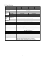
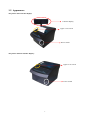
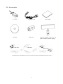
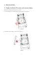
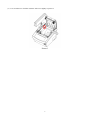
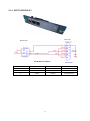
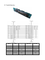
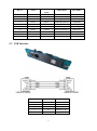
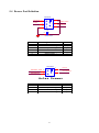
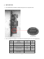
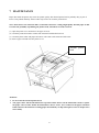
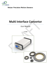
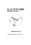
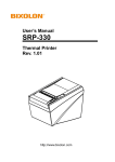
PP7X PRINTER USER’S MANUAL PINNACLE TECHNOLOGY CORP. Tel: +86-592-5710087 Http:// www.aclas.com Fax: +86-592-5710029 Email: [email protected] Safety Precautions Before using the present appliance, please keep the following safety regulations in order to prevent any hazard or material damage. 1. WARNING (1) Connect the printer with a reliable grounded power receptacle. Do not plug with large electronic machines in one multi-outlet, which can provoke power fluctuation or over-heating, even a fire. (2) (3) (4) (5) Do use the only supplied adapter. Do not keep the machine in a hot, wet or polluted place. Do not plug in or unplug with your hands wet. Do not pull the cable to unplug. This can damage the cable, which is the origin of a fire or a breakdown of the printer. 2. CAUTIONS (1) Install the printer on the stable surface. If the printer falls down, it may be broken and hurt you. (2) If you find a strange smoke, odor or noise from the printer, unplug it at once and call your dealer. (3) Do not try to disassemble, repair or remodel it for yourself. Call your dealer if you need these services. (4) Do not let water or other foreign objects in the printer. If this happened, switch off and unplug the printer before calling your dealer. (5) (6) (7) (8) Switch off the printer if you will not use it in a long time. Make sure the switch is off when plug or unplug the power. Do not use the printer when it is out of order. Switch off and unplug the printer before calling your dealer. Keep this manual for future use. CONTENTS 1 2 3 4 5 6 7 8 INTRODUCTION ............................................................................................................................................. 1 1.1 Application Range ............................................................................................................................. 1 1.2 Unique Functions ............................................................................................................................... 1 1.3 Advanced Functions and Features ..................................................................................................... 1 1.4 Specifications ..................................................................................................................................... 2 1.5 Appearance ........................................................................................................................................ 3 1.6 Accessories ........................................................................................................................................ 4 INSTALLATION ............................................................................................................................................... 5 2.1 Display Installation (The printer with customer display) .................................................................. 5 2.2 Communication Board Replacement ................................................................................................. 7 2.3 Paper Installation ............................................................................................................................... 8 SETTING THE PRINTER .............................................................................................................................. 10 3.1 Using the Printer .............................................................................................................................. 10 3.2 Connecting the Computer ................................................................................................................ 10 3.3 Connecting the Power Supply...........................................................................................................11 SELF TEST ..................................................................................................................................................... 12 CONNECTING THE CABLES ...................................................................................................................... 12 5.1 Serial Interface ................................................................................................................................. 12 5.1.1 RS232 (D9) .............................................................................................................................. 12 5.1.2 RS232 (PHONE8C) ................................................................................................................. 13 5.1.3 RS232 (PHONE6C) ................................................................................................................. 14 5.1.4 RS232 (PHONE4C) ................................................................................................................. 15 5.2 Parallel Interface .............................................................................................................................. 16 5.3 USB Interface .................................................................................................................................. 17 5.4 Drawer Port Definition .................................................................................................................... 18 DIP SWITCH................................................................................................................................................... 19 MAINTENANCE ............................................................................................................................................ 21 TROUBLESHOOTING .................................................................................................................................. 22 1 INTRODUCTION 1.1 Application Range The quality of easy operation, high speed and stable performance has made the printer one of the most economical and practical printing devices. It has been applied in various fields such as supermarkets, department stores, hotels, franchises, finance, telecommunications and ticket business as a receipt printer. And it could be combined with cash registers, touch-pos terminals, computers and other equipments. There are two kinds of printers about PP7X Printer: the printer with customer display, and the printer without customer display. 1.2 Unique Functions ※ Oblique paper-sensor. Detect the paper precisely, even if the paper is stuck to the end of paper slot or the PP7X is positioned in different places (desktop or hang on the wall). ※ Unique mechanism to replace paper-cutter easily without opening the printer cover. ※ Special paper cutter design (the movable cutter is on the upper side). You can easily eliminate paper jam by opening the upper cover; while using traditional printers (brand E,C) in market whose movable cutter is designed in the front seat, you must open the front cover and move the gear to withdraw the cutter manually (you cannot withdraw the cutter without opening the cover). ※ With agile black mark sensor: locate printing position quickly, support detection in left and right direction. Also could connect with optional operator/customer display and function keyboard to work as a receipt and fiscal printer. ※ RF2.4G/RF433MHz applies Pinnacle‟s patented CSMA power-saving protocol (P-tooth) to establish reliable and stable many-to-many wireless communication. ※ Firstly introduced POS printer which adopts wireless communication (2.4G P-tooth, BT, and WIFI) in the market, avoiding wire clutter on the desk. ※ The most complete options of port modules in the world. 4 types of wireless communication modules: WIFI, BT, P-tooth (2.4G Pinnacle protocol), 433MHz (100M long distance); four types of wire communication modules: RS232 port, USB port, parallel port, and Ethernet port. Customers could choose the module according to the system that they used. 1.3 Advanced Functions and Features ※ ※ ※ ※ High print speed, max: 250mm/s(PP7XHX) Unique easy-loading paper mechanism. Two options: with auto-cutter mechanism (PP71X), and without auto-cutter low-price mechanism (PP70X). Can be fixed on wall. And can work with big paper roll outside to reduce changing paper frequency. 1 1.4 Specifications Optional type PP721MX PP721HX PP71MX PP71HX Speed 150mm/s 250mm/s 150mm/s 250mm/s Power Supply DC24V /2A Print Method thermal print Resolution 203dpi Paper type Paper Paper width Thermal paper 57.5±0.5mm Paper roll diameter Paper installation type Character print 79.5±0.5mm 80mm Unique mechanism that make paper installation easily Character set ANK character set, Chinese GB2312, Traditional Chinese BIG5, 12×24 dots, 24×24 dots Number of columns 48 columns Barcode type UPC-A, UPC-E, Code128, EAN128.Jan8, Jan13(EAN), Interleaved 2 of 45, Codabar Data receiving buffer 4KB Flash memory 8Mbit Optional function Interface Fiscal (with operator and customer display), customer display, operator display, black mark detector, GPRS module Ethernet, parallel, RS232, USB, WiFi, BT, P-tooth Cash drawer driver 2 ports (compatible with EPSON) Printer head life 150km (recommend to use high quality thermal paper, such as OJI, PD-160R or Aclas paper.) Paper-cutter life 500,000 times Cash drawer impulse DC 24V/1A Work Temperature 0℃ ~ 40℃ Work Humidity Driver Printing command Size 5%R.H. ~ 90%R.H. Win9X, WinME, Win2000, WinNT, WinXP, compatible with EPSON Compatible with command ESC/POS The printer with customer display: 226.5*176*208mm; The printer without customer display: 196.5*145*135mm 2 1.5 Appearance The printer with customer display: Customer display Upper cover switch Power switch The printer without customer display: Upper cover switch Power switch 3 1.6 Accessories AC adapter PC Disk serial cable AC power cord Paper roll USB cable User manual Customer display (only for the printer with the customer display) parallel cable Communication cable (Different types of printer will match with different kinds of cable.) 4 2 INSTALLATION 2.1 Display Installation (The printer with customer display) Install customer display before using the PP7X printer. (1) Press printer upper cover button upwards to open the printer cover as picture1. Picture1 (2) Install the customer display via the interface as picture 2. Picture 2 5 (3) Use screwdriver to lock the customer with screw tightly as picture 3. Picture 3 6 2.2 Communication Board Replacement Note: Make sure that PP7X is powered off when you are changing the communication board. Power off PP7X for more than 10s, then the communication board can be replaced. (1) Use cross screwdriver to unscrew the two screws of the communication board as picture 4. the two screws Picture4 (2) Take off the communication board and replace it as picture 5. Picture 5 (3) Install the new communication board along the slot, lock the two screws. We suggest that you should tighten the two screws side by side to avoid damaging the main board. Note: Don’t press the communication board if it does not at the same level with the printer. 7 2.3 Paper Installation Note: Bad quality thermal paper with rough surface and low sensetivity may reduce the life time of the printer head, please use high quality thermal paper, such as OJI, PD-160R or Aclas paper. (1) Make sure that the printer is not receiving data; otherwise, data may be lost. (2) Open the printer upper cover by pressing the cover button as picture 6. upper cover button Picture 6 (3) Insert the paper roll to the printer as picture 7. Picture 7 8 (4) Be sure to note the correct direction thats the paper comes off the roll shown as picture 8. Wrong Right Picture 8 (5) Pull out a small amount of paper to make it parallel with the alignment line as picture 9,and then close the upper cover by pressing its front middle part until you hear a „click‟ sound. close the cover by pressing here the alignment line Picture 9 (6) After closing the upper cover,tear off the paper as picture 10. Picture 10 9 3 SETTING THE PRINTER 3.1 Using the Printer Power indicator light To prompt error To prompt the paper is run out Press the button once to advance paper once line. You can also hold down the Feed button to feed paper continuously. 3.2 Connecting the Computer (1) Power off the printer. (2) Plug the communication cable securely into the printer, then attach the other end of the cable to the computer. (3) If the cable connector is shown as picture 11, tighten the two screws on both sides of the cable connector after connecting. Picture 11 10 3.3 Connecting the Power Supply ※ CAUTIONS When connecting or disconnecting the power supply from the printer, make sure that the power supply is not plugged into an electrical outlet. Otherwise you may damage the power supply or the printer. If the power supply’s rated voltage and your outlet’s voltage do not match, contact your dealer for assistance. Do not plug in the power cord. Otherwise, you may damage the power supply or the printer. (1) Make sure that the printer‟s power switch is turned off, and the power supply‟s power cord is unplugged from the electrical outlet. (2) Check the label on the power supply to make sure that the voltage required by the power supply matches that of your electrical outlet. (3) Plug in the power supply‟s cable as picture 12. Power connector AC Adapter Picture 12 11 4 SELF TEST Press key „Feed‟ and hold it, and then power on the machine at the same time, it will print a piece of Test Page. The information of this Test Page includes the printer‟s model, version, IP address (Ethernet port), ID and the default setting of the dip switch when leave factory. 5 CONNECTING THE CABLES NOTE: Before connecting any of the cables, make sure that both the printer and the host are turned off. 5.1 Serial Interface There are four kinds of serial interface. Details are as follows: 5.1.1 RS232 (D9) Host side Printer side RS233 GND /RTS /RXD /CTS /TXD RS232 GND 5 9 4 8 3 7 2 6 1 /RTS /RXD /CTS /TXD HOLE1 DSUB 9PIN/公座焊接型 The definition of D9-P9 5 9 4 8 3 7 2 6 1 HOLE1 DSUB 9PIN/母座焊接型 Pin No. Signal Name Direction Function 2 3 5 7 8 TXD RXD GND CTS RTS Output Transmit Data Input Receive Data ——— Frame Ground Input Clear to Send Output Ready To Send 12 5.1.2 RS232 (PHONE8C) Printer Side Host Side The Definition of D9-P8 Note: Users could install a network connector (8-8) to extend the D9-P8 communication cable freely. Pin No. Signal Name Direction Function 3 RXD Input Receive Data 4 RTS Output Ready To Send 5 TXD Output Transmit Data 6 CTS Input Clear to Send 8 GND ——— Frame Ground 13 5.1.3 RS232 (PHONE6C) Host Side Printer Side /RTS The Definition of D9-P6 Pin No. Signal Name Direction Function 1 CTS Input Clear to Send 3 GND ——— Frame Ground 4 RXD Output Receive Data 5 TXD Output Transmit Data 6 RTS Output Ready to Send 14 5.1.4 RS232 (PHONE4C) Host Side Printer Side The Definition of D9-P4 Pin No. Signal Name Direction Function 2 GND ——— Frame Ground 3 RXD Input Receive Data 4 TXD Output Transmit Data 15 5.2 Parallel Interface Pin No. Source Compatibility Mode Nibble Mode Byte Mode 1 Host nStrobe HostClk HostClk 2 Host/Printer Data 0 - Data 0 3 Host/Printer Data 1 - Data 1 4 Host/Printer Data 2 - Data 2 5 Host/Printer Data 3 - Data 3 6 Host/Printer Data 4 - Data 4 7 Host/Printer Data 5 - Data 5 8 Host/Printer Data 6 - Data 6 16 Pin No. Source Compatibility Mode Nibble Mode Byte Mode 9 Host/Printer Data 7 - Data 7 10 Printer nAck PtrClk PtrClk 11 Printer Busy PtrBusy/Data3,7 PtrBusy 12 Printer PError AckDataReq/Data2.6 AckDataReq 13 Printer Select Xflag/Data1,5 Xflag 14 Host nAutoFd HostBusy HostBusy 15 Printer nFault nDataAvail/Data0,4 nDataAvail 16 Host nInit nInit nInit 17 Host nSelectIn 1284-Active 1284-Active GND GND GND 18~25 5.3 USB Interface Pin No. Signal Name Function Shell Shield Frame Ground 1 VBUS Host Power 2 D Data Line(D-) 3 D Data Line(D+) 4 GND Signal Ground 17 5.4 Drawer Port Definition DRAWER 1 DRAWER1# 2 P+24V 3 DRAWER_SW# 5 DRAWER2# 4 6 PHONE6P6C C12 2 1 102/2KV/DIP GND EPSON POS PRINTER Drawer Pin No. 1 2 3 4 5 6 Signal name Frame ground Drawer kick-out drive signal 1 Drawer open/close signal +24V Drawer kick-out drive signal 2 Signal ground Direction Output Input Output - DRAWER DRAWER_SW# 2 DRAWER2# 4 1 P+24V 3 DRAWER1# PHONE4C Aclas Drawer Pin No. 1 2 3 4 Signal name +24V Drawer open/close signal Drawer kick-out drive signal 1 Drawer kick-out drive signal 2 18 Direction Input Output Output 6 DIP SWITCH The communication port module is with dip switch, please refer to the picture below: The Dip Switch There are 8 Dip Switch altogether, each switch has its own function, please refer to the diagram below: DIP-8 Function ON OFF SW-1 Select cutter Yes No SW-2 Select buzzer Yes No SW-3 Reserve SW-4 Select hardware flow control Yes No SW-5 Select print density Light Dark SW-6 Select print density Light Dark SW-7 Select baudrate SW-8 Select baudrate 19 a) SW-5 and SW-6 are used to set print density, the on/off status of SW-5 and SW-6 is able to compose different density. Please refer to the table below: SW-6 Heat Time Density ON ON 600us Dark ON OFF 500us Middle Dark OFF ON 420us Middle Light OFF OFF 360us Light SW-5 NOTE: We suggest that you should not select ‘dark’ density level, or it may reduce the life time of the printer head for 15%. b) SW-7 and SW-8 are used to control baudrate, the on/off status of SW-7 and SW-8 is able to compose different baudrate. Please refer to the diagram below: SW-8 SW-7 Baudrate ON ON 9600 ON OFF 19200 OFF ON 38400 OFF OFF 115200 NOTE: 1) As for the Dip Switch is relatively tiny, yet we need some tools that are relatively tiny to switch them, for example, the head of ball pen or pencil. 2) Press key ‘Feed’ and hold it, and start the machine at the same time, it will print a piece of Test Page. The function of the dip switch is based on the information of this Test Page. 3) The baudrate of wireless 2.4G/wireless 433 printer is fixed at 9600 and that of the USB printer is 460800. The two kinds of baudrate could not set via the dip switch. 20 7 MAINTENANCE Paper dust inside the printer may lower the printer quality. The thermal printer head is probably dirty, if part of letters is not printed distinctly. Please follow steps below to clean the printer head. Note: If the dust is not cleaned in time, it will lead to defective cooling. High-quality thermal paper is able to reduce the possibility of polluting the printer head, and almost no need to clean it. (1) (2) (3) (4) Open the printer cover and remove the paper if exists. Clean the printer head with a cotton swab moistened with alcohol solvent. Clean the platen roller and paper end sensor with cotton swab moistened with water. Insert a paper roll and close the printer cover. Thermal printer head Attention: Do not touch the thermal printer head. The paper cutter will become blunt after a period of time. Please ask the maintenance man to replace the paper cutter in time. When the maintenance doesn’t arrive, users could tear the paper with their hands and close the function of cutting paper automatically via dip switch (please refer to chapter 6 for more detail). 21 8 TROUBLESHOOTING 1) Paper is near end or used up. If the paper is near end or used up, the “Paper out” and “Power” indicator light will be illuminated at the same time. In this case, the printer will stop printing. And then install a new paper roll, the printer will continue printing. 2) a. b. c. The printer could self-test but could not print. Make sure the connection cable between the PC and the printer connects securely. Make sure the connecting port of the printer is not being used. Otherwise, remove the port. If the problem still exists, contact our after-sales service center. 3) Removing paper deviation Press paper feed key to feed paper, by which the printer will adjust the paper automatically; otherwise, please turn the power off, open paper cover to reinstall paper. Note: Using high quality of thermal paper with standard width and smooth surface could avoid paper deviation. 4) The printed character is unclear. a. Check that the thermal printer head is clean enough. Otherwise, please refer to Chapter 7 to clean it. b. Make sure the used paper meets the required specification, please refer to Chapter 1.4. Note: Using high quality of thermal paper with standard width and smooth surface could avoid this problem. If the problem still exists, contact our after-sales service center. 5) a. b. c. Some columns could not be printed. Make sure the printer head is not stuck with dust. Otherwise, please refer to Chapter 7 to clean it. Make sure there is not a paper jam. If there is, remove it. If the problem still exists, contact our after-sales service center. 6) Paper feeding unsteadily a. Make sure the rubber platen is not stuck with foreign matter. If not, clean it with cotton swab with water. b. If the problem still exists, make sure the motor gear of the platen is not broken. If not, contact our after-sales service center. 7) Removing a paper jam a. Turn the power off. b. Open paper cover, remove the jammed paper. c. Reinstall paper to the printer correctly, close paper cover. Make sure the paper cover is closed securely (refer to Chapter 2.3 (5)). Otherwise, paper-cutter may lock. Note: Using high quality of thermal paper with standard width and smooth surface could avoid paper jams. 8) Removing paper-cutter lock a. Check the upper cover is closed well. If not, push hard on the cover until it reach its work position. Then the printer will perform cutter-retract automatically until the cutter retracts to its normal position. b. Repower on the printer, by which the cutter will back to its normal position. 22 Note: Close the upper cover securely could avoid paper-cutter lock. If the problem still exists, contact our after-sales service center. 9) The temperature of the printer head is too high. Power off the printer, and then restart it until the temperature is cooling down. 23 Head Office: 4F, NO.270, Sec 3, Nan-kang Road, Taipei, Taiwan Factory 1: North 4th Floor, Guangxia Building, Torch High-Tech Zone, Xiamen, China Factory 2: No.1, Fangshannan Road, Xiang’an Industrial Zone, Xiamen, China DPP701ENV2-22