1
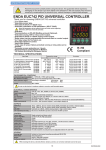
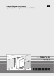
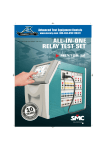
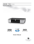
Gama PTEs ingles v5_SMC fichas 30/5/15 13:22 Página 1
Gama PTEs ingles v5_SMC fichas 30/5/15 13:23 Página 2
ELECTRONIC PTE RANGE
Protective relay test sets w ith direct on-board control
and computer-based test automation
THE ELECTRONIC PTE TEST EQUIPMENT RANGE
The electronic PTE test equipment range has been designed for maximum efficiency and
simplicity when testing protective relays in the field. These universal, rugged and powerful
units provide the required accuracy and performance to test any electromechanical, static, or
numerical relay. Output waveforms are digitally synthesized, and completely isolated from the
mains supply. The signal is then electronically amplified to attain up to 50 A or 300 V with an
effective power of 100 VA.
FLEXIBILITY
The range includes four products: the PTE-300-V, with three output channels, and the smaller PTE100-V, with one channel only, are mainly designed for voltage-related protections like generator,
motor and synchronizing relays. The other two (PTE-50-CET and the one-channel version PTE-50-CE)
are specially powerful in current-based testing .
PTE-50-CET
Each output channel in these units can be switched between current and voltage injection by just
pressing a button. Amplitude and phase angle can also be adjusted independently in each
channel. One of the biggest advantages in the PTE sets is their ability to communicate to each
other, in order to use all their output channels simultaneously. You can purchase several simple
units for the most frequent testing and, when time arrives for more demanding tasks, interconnect
two or three according to the application’s requirements. This is a cost-effective solution when you
need more than one test set.
Furthermore, the PTE units can also be used in combination with equipment from other
manufacturers, thanks to their built-in external synchronization input.
Need computer-generated reports? Not only does the PTE range feature the best manual control
board in the market, but also the possibility to operate automatically under the control of optional
software from a standard computer. This capability is especially useful when a great number of
different protections must be tested periodically. Relay types and test routines are stored in a
custom-defined database, so that you only need to double-click on each installed relay’s entry to
perform the complete test process and to save and produce a report in a fully unattended manner.
The automatic testing software can also control combinations of several PTE units as if it was a
single device.
PTE-300-V
POWER
Behind the 100-VA output power in the PTE channels, you will find a generous duty cycle and a
great number of test resources. For example, several channels can be controlled from a single
button, even if they belong to various interconnected units, thanks to the master/slave function.
And you can refer the phase angle of each channel or the base frequency of the harmonics function
to an incoming signal from an external generator, or setup ROCOF frequency ramps in less than one
minute without a computer.
PTE-50-CE
The PTEs feature an idle power mode to save energy and keep the amplifiers cool when testing
low impedance relays. Each output channel provides an independent neutral, which enables the
interconnection of two or more channels in series or in parallel with absolute freedom.
The optional PTE-SER plug allows the injection of up to 50A with a compliance voltage of up to 60V
in the PTE-50-CET.
OUTPUT CHARACTERISTICS
Output channels
PTE-50-CE
PTE-50-CE Pro
PTE-50-CET
PTE-100-V
1
2
3
1
3
3 x 0-50 A
0-8 A
3 x 0-8 A
3 x 0-150V
0-300 V
3 x 0-300 V
Current per channel
PTE-100-V
Voltage per channel
Frequency
2
Chronometer
0-50 A
0-150 V
0-150 V, 0-140 V
PTE-300-V
1º - 7º harm. 1º - 7º harm., 40-70 Hz 1º - 7º harm.
40-420 Hz
Yes
No
Gama PTEs ingles v5_SMC fichas 30/5/15 13:23 Página 3
ASSISTED MANUAL CONTROL
The comprehensive and well-designed control board in the PTE units
provides fast and accurate operation for the simplest one-shot testing to the
most complex dynamic fault simulation. The board’s design and the studied
position of each control and button is uniform and coherent, so that all the
units are operated in the same way. The three-channel versions feature a
master/slave function that allows to control and adjust two or three
channels simultaneously from channel #1. You just adjust the pre-fault and
fault quantities, launch the simulation and note the reading from the
chronometer.
Dynamic simulation
Each channel can store two sets of amplitude (voltage or current) and
phase angle parameters in memory. You can then step into fault state from
zero or from non-fault values. You can also edit and playback digitized
transients in COMTRADE format from an external PC using optional software.
Digital timer
Control BUS
Harmonics selector
UNO
(PTE-50-CE + PTE-100-V)
Complete single-phase system with
chronometer, frequency generator and
two reversible channels
(50 A + 300 V, 50 A + 8 A,
150 V + 300 V or 150 V + 8 A)
OTRO
(PTE-50-CET + PTE-100-V)
4-channel system with chronometer
and frequency generator
(3 x 50 A + 300 V, 150 A + 300 V,
3 x 150 V + 8 A, 450 V + 8 A etc.)
The EuroSMC’s exclusive PTE BUS, supplied as standard equipment, allows
the interconnection of up to five PTE units in order to use all their output
channels simultaneously. Phase and frequency synchronization signals, as
well as output control messages, timer start/stop commands and trip signal
detection messages, are transmitted by this high-speed bus in real time. Any
unit can be set as master or slave in the system’s operational hierarchy.
Current / voltage channel
The PTE BUS integrates the resources of each individual unit into a single
virtual system that can be operated from the
master unit or from an external computer.
Digital Instrumentation
All the instruments are digital, including the
chronometer, the frequency generator and the
injection measurement displays. Quantities are
adjusted with contact-free digital encoders on
high-contrast LED indicators. The adjustment
speed and resolution is easily controlled by
selecting the digit to be modified. The
chronometer features six start/stop modes
selectable by pressing a button, and can be set to
display milliseconds or cycles of the working
frequency. The frequency generation module
features a fully programmable ramp for ROCOF
testing and a direct adjustment method with two
modes: absolute frequency and delta
(incremental) mode referred to an external
signal’s frequency.
TRES
(PTE-50-CET + PTE-300-V)
Complete three-phase system with up
to 6 current or 6 voltage channels
(3 x 50 A + 3 x 300 V, 150 A + 900 V,
3 x 50 A + 3 x 8 A,
3 x 50 A + 900 V, etc.)
3
Gama PTEs ingles v5_SMC fichas 30/5/15 13:23 Página 4
ELECTRONIC PTE RANGE
Selectable frequency and phase angle reference
The frequency and phase reference for the generation of the sinusoidal output can be chosen from
various sources by just pushing a toggle button. You can select, for example, an internal frequency
generator, the supply’s line, an external signal at the synch input or the active source in another PTE
unit connected to the bus.
INTEGRAL PROTECTION
Output amplifiers are safeguarded against overheating and overload by electronic protections that
resume the output automatically when the trouble is cleared out. Furthermore, the complete
isolation between amplifiers prevent accidental damages from being propagated between channels,
so that the healthy channels in the unit can still be used while the damaged module is repaired.
Lightweight nylon bag
PTE-300-V
4
Gama PTEs ingles v5_SMC fichas 30/5/15 13:23 Página 5
PTE-50-CE PRO
Any test set in the PTE range can be upgraded with an additional voltage
source, the PTE-FCN option. This electronic, independent source can be
adjusted in amplitude, frequency, and phase angle. It comes installed as
standard with the 'Pro' versions of the PTE sets, but it can also be
purchased separately and mounted by the user inside the unit's lid in a few
minutes.
The PTE-FCN will dramatically increase the relay types that can be tested,
usually avoiding unnecessary investment in three-phase equipment. The
PTE-50-CE Pro, for example, is an unbeatable single-phase test set for
directional, frequency, synchronisation and generator protection relays.
PTE-FCN optional voltage source
Current / voltage reversible channels
100 VA power per channel
Up to 50 A and up to 300 V per channel
Manual, direct or automatic, pc-controlled operation
Multi-unit bus architecture with centralized control
External signal synchronization input
Electronic protection against overload and overheating
Supply-independent digitally generated waveform
APPLICATIONS OVERVIEW
Automatic generation of 2nd to 7th harmonics
(See Compatibility Chart on the next page)
• Single- and three-phase testing of electromechanical,
static and numerical protective relays
Digital multimode chronometer
Programmable frequency ramp
Serial and parallel interconnection of channels
Up to 150 A and 900 V single-phase injection
• Motor protection testing
• Differential protections testing
• Generator protection testing
• Reclosing and synchronization relay testing
• Low-voltage protections testing at line levels
• Impedance relay testing
• Directional protection testing
• COMTRADE transient playback
Depending on model
• Automatic relay testing and reporting
In three-channel models
5
Gama PTEs ingles v5_SMC fichas 30/5/15 13:23 Página 6
ELECTRONIC PTE RANGE
TESTABLE IEEE RELAYING FUNCTIONS
IEEE No.
2
21
21
21
24
25
27
32
32
37/76
40
46
46N
47
49
50
51
55
59
60
64
67
67N
78
79
81
82
85
87
91
92
94
Protective device
PTE-50-CE
PTE-100-V
PTE-300-V
PTE-50-CET
UNO
PTE-100-V
PTE-100-C
PTE-300-V
PTE-50-CE
PTE-300-V
PTE-100-C
PTE-50-CET
PTE-100-V
TRES
✔
Pro
✔
✔
✔
✔
Pro
Pro
✔
❏
✔
✔
✔
❏
✔
✔
✔
✔
✔
✔
✔
✔
✔
✔
✔
✔
✔
✔
✔
✔
✔
✔
✔
✔
✔
✔
✔
✔
✔
✔
✔
✔
✔
✔
✔
✔
✔
✔
✔
✔
✔
✔
✔
✔
✔
✔
✔
✔
✔
✔
✔
✔
✔
❏
✔
✔
✔
✔
✔
✔
✔
✔
✔
✔
✔
✔
✔
✔
✔
✔
✔
✔
✔
✔
✔
✔
✔
✔
✔
✔
✔
✔
✔
✔
✔
✔
✔
✔
✔
✔
✔
✔
✔
✔
✔
✔
✔
✔
✔
✔
✔
✔
✔
✔
✔
✔
✔
✔
✔
✔
✔
✔
✔
✔
✔
■
■
■
■
✔
✔
■
■
■
✔
✔
✔
✔
✔
✔
✔
✔
✔
✔
✔
✔
✔
✔
✔
✔
✔
✔
✔
✔
✔
✔
✔
✔
■
✔
✔
✔
✔
✔
✔
✔
✔
✔
✔
✔
✔
✔
✔
✔
✔
✔
✔
✔
✔
✔
✔
✔
✔
✔
✔
✔
✔
✔
✔
✔
✔
✔
Pro
✔
Pro
✔
✔
✔
✔
✔
Pro
✔
Pro
✔
✔
✔
Pro
✔
✔
✔
✔
✔
✔
✔
✔
✔
✔
✔
✔
✔
✔
✔
✔
✔
✔
■
✔
✔
✔
✔
✔
✔
✔
✔
✔
✔
Timing relay
Distance 1Ø
Distance (open delta)
Distance 3Ø
Volts / Herz
Synchronization
Undervoltage AC / DC
Directional power 1Ø
Directional power 3Ø
Under- and Overvoltage DC
Loss of field
Reverse phase sequence
Negative sequence overcurrent
Reverse phase voltage
Thermal relay
Instantaneous overcurrent
Timed overcurrent
Power factor relay
Overvoltage
Voltage balance
Neutral detection
Directional overcurrent
Directional neutral overcurrent
Angle / out of step
Reclosing relay
Frequency relay
DC reclosers.
Carrier or pilot wire protection
Differential protection
Directional voltage
Directional power and voltage
Tripping relay
✔
✔
✔
✔
✔
✔
✔
❏ Options required
PTE-FCG
PTE-12
PTE-30-CH
PTE-GPS
❏
✔
✔
✔
✔
✔
✔
✔
✔
✔
✔
✔
✔
✔
✔
✔
✔
✔
✔
✔
✔
✔
Pro: with the PTE-FCN module
✔
✔
✔
✔
✔
✔
✔
✔
✔
✔
✔
✔
✔
✔
✔
✔
✔
✔
✔
✔
✔
■ Partially tested
OPTIONAL ACCESSORIES
The PTE-FCG battery simulator can be used externally or fitted inside the lead of the three-channel
models. It provides a 60W supply of 48, 125 or 250 VDC to energize any electronic or numerical
relay during the tests.
The PTE-12 interface allows the integration of a personal computer in the PTE-BUS for software
based operation of the PTE equipment. It also implements the PTE-COM command interpreter that
enables the user to build his own automation applications using popular programming languages
like Visual Basic® or C++, as well as any scripting language featuring RS-232 communications
control.
The PTE-GPS receiver enables the synchronization of two test sets located at any distance in order
to initiate a software-based test simultaneously with an accuracy of 1 microsecond.
PTE-SER
The PTE-SER set of connectors allows the interconnection of two or three channels in series in the
PTE-50-CET when currents of up to 50 A are required on extremely high burdens, with compliance
voltages up to 60 V.
The PTE-30-CH handheld chronometer can complement the PTE-300-V and PTE-100-V models for
time-based testing if no other PTE unit with a built-in chronometer is available. It features the same
functions as the built-in version and can measure the time of any electrical event in dry contacts or
voltages up to 250Vac/dc with an accuracy of 1 ms.
The PTE-FCN module, featured as standard in the PTE-50-CE Pro, provides an additional voltage,
frequency and phase angle adjustable source, remarkably increasing the relay types that can be
tested. It can be purchased separately and installed inside the unit's lid in a few minutes.
6
Gama PTEs ingles v5_SMC fichas 30/5/15 13:23 Página 7
SOFTWARE APPLICATIONS
The PTE range of relay testing equipment offer the best of both worlds: a
powerful, yet easy to use control panel and the capability to communicate
with a computer to do the testing and the reporting automatically, by means
of optional software applications:
ROOTS
ROOTS (Relay Object-Oriented Test Software) provides the best solution to
the testing of today’s multifunctional IEDs by performing accurate fault
calculation, sequential test execution, and reporting automatically.
ROOTS is an optional product for computer-based operation of EuroSMC
relay test sets. ROOTS is developed using the latest Microsoft.NET®
technology and is available for 32-bit and 64-bit Windows XP, Vista and
Windows 7 platforms. ROOTS storage files are self-contained databases
where relay data, characteristics, custom formulas, test routines and report
definitions are saved according to a simple hierarchy that is flexible and
easy to understand, with a modular architecture. Relays can be defined as
templates by using equations instead of fixed values for the device’s
characteristics and definitions. Relay characteristics can be defined in
ROOTS from scratch or imported from RIO files. Test procedures defined
within ROOTS can be directly executed on a connected EuroSMC test set.
ROOTS
For every functional module of the device under test - Distance, Overcurrent,
Differential module, RIO, etc - multiple tests can be attached from a wide
choice of test types (click sequence, search, reclose, CB failure, SOTF, fuse
fail, etc) including scheme-oriented tests.
ROOTS features a powerful interactive graphical editor for geometrical
definitions of protective characteristics and zones. Lines and curves can be
drawn in free hand mode, imported from a templates library and / or
adjusted using numerical values and coordinates.
ROOTS implements a friendly, easy to use interface, for the quick and
accurate configuration of all equipment features, device settings, test
modules, test results and reports. The test report can be easily customized
and exported according to user needs.
ROOTS users are covered by EuroSMC’s lifetime update warranty, which
provides free, unlimited access to new releases and software modules of
ROOTS.
EuroFAULT
EuroFAULT
If you have oscillographic recordings of faults and transients in digital
COMTRADE format, you can play them back into your relay with EuroFAULT.
You only need to open the file from the program, assign the voltage and
current components to the available channels in your PTE unit or
combination and click on PLAYBACK.
PTE-COM
PTE-COM is the command language used by software applications to control
the PTE equipment from a computer. The PTE-COM commands, interpreted
by the PTE-12 interface during the software-controlled test process, are
available to the users for the development of their own custom applications
and test automation procedures, if needed.
PTE-COM sample application
Remember that you will need the PTE-12 interface to control the PTE units
from a computer, regardless the software application used.
7
Gama PTEs ingles v5_SMC fichas 30/5/15 13:23 Página 8
ELECTRONIC PTE RANGE
SPECIFICATIONS
REVERSIBLE OUTPUT CHANNELS
PTE-50-CET
PTE-50-CE
PTE-300-V
PTE-100-V
3
1
3
1
Serial or parallel
Serial or parallel
Current ranges
0-0.330 A / 0-8.000A / 0-25.00A / 0-50.00A
0-0.330A / 0-8.000A
Voltage ranges
0-6.25V / 0-150.0V
0-6.25V / 0-150 V / 0-300V
Harmonics generated
1st – 7th automatic in each channel
PTECCEN - Version 5
Interconnections
Manual, up to 420 Hz
Phase angle
0-359.9º
Frequency range
Parametric: 40.00-420.0 Hz
Power per channel
Transient: 0.5-5000 Hz
100 VA
Accuracy
±0.5%
Distortion
1% máx.
FREQUENCY GENERATOR (PTE-300-V, PTE-100-V)
DIGITAL CHRONOMETER (PTE-50-CET, PTE-50-CE)
Range
0.001 - 99999 s. o 0.1 – 9999.9 cycles
Accuracy
±0.01% of reading ±1 digit
Output ON or OFF
Pre-fault / fault state switching
PTE BUS event
External START signal
NO or NC contact
Voltage ON / OFF
PTE BUS event
Start modes
Stop modes
Modo diferencial
40-420 Hz
0.001-10 Hz
Resolution
0.01 / 0.1 / 1 Hz
0.001 / 0.01 / 0.1 Hz
Accuracy
1 digit ±0.003 Hz
1 digit ±0.001 Hz
Ramp limits
0.1 – 10.0 Hz/s.
_
Ramp lapses
0.1 – 10.0 s.
_
PTE-FCN OPTION
TRIP MONITOR
Dry contact input
Modo normal
Range
Open circuit voltage: 10.2 Vdc
Output power
30 VA (70 – 140 Vac)
Short circuit current: 25 mA
Voltage output
0 – 140 Vac (res.: 0.1V)
Voltage input
Fuse protected
Max. current
0.45 A (0 – 70 Vac)
5 - 250 Vac/dc
Phase angle
0 – 359.9º (res.: 0.1º, Vout> 5V)
Frequency
Impedance: 19 kΩ
Phase reference
Fuse protected
STANDARD ACCESSORIES
EXTERNAL REFERENCE INPUT
Input impedance
Signal range
40 – 70 Hz (res.: 0.1 Hz)
AC supply or internal generator
Voltage input
Current input
Complete 2-m / 6,5 ft. test lead set
47 kΩ
25 mΩ
1.5-m / 4,9 ft. power cord
5 – 300 Vac
0.1 – 25 Aac
4-mm terminal adapters
Frequency range
4-mm crocodile clip set
40 - 70 Hz
RS-232 communications cable
PTE BUS interconnection cable
GENERAL
Weight
Dimensions
(mm)
inches
Auxiliary voltage output
Supply power
Temperature range
DISTRIBUTED BY:
PTE-50-CET
PTE-300-V
25 Kg / 55.1 lb.
22 Kg. / 48.5 lb.
PTE-50-CE
PTE-100-V
Set of replacement fuses
13.5 Kg. / 29.7 lb. 13.5 Kg. / 29.7 lb.
Coaxial BNC to 4-mm connection cable
300 x 200 x 200
11.8 x 7.8 x 7.8
Nylon bag for test set and accessories
442 x 327 x 200
17.4 x 12.8 x 7.8 in
Calibration software
110 Vca / 0.3 A máx.
230 / 110 Vca ±10%
Storage : -20 to 70ºC / -4º F - 158º F / Operation: 0 to 50ºC / 32ºF - 122º F
User manual in English
Certificate of calibration
EuroSMC, S.A.
Polígono industrial P-29, Calle Buril, 69
28400 Collado Villalba. Madrid (Spain).
Tels: +34 91 849 89 80 Fax: +34 91 851 25 53
www.eurosmc.com
e-mail: [email protected]
Please note: Due to the continuous research and development by EuroSMC, specifications in this catalog may be changed without previous notice.
Number of channels