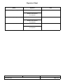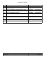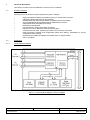
1
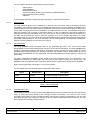
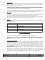
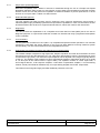
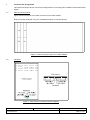
CCII Systems (Pty) Ltd Registration No. 1990/005058/07
C ommunications
C omputer I ntellig ence
I nteg ration
Hardware Reference and Installation Manual
for the
1 Gbit/s Copper Medium
and
2 Gbit/s Fibre Medium
Fibre Channel Adapter
C²I² Document No.
CCII/FC/6-MAN/003
Document Issue
1.3
Issue Date
2009-08-20
Print Date
2009-08-21
File Name
P:\Fibrechn\TECH\MAN\CFCMAN03.WPD
Distribution List No.
DN 0501
© C²I² Systems The copyright of this document is the property of C²I² Systems. The document is issued for the sole
purpose for which it is supplied, on the express terms that it may not be copied in whole or part, used by
or disclosed to others except as authorised in writing by C²I² Systems.
Document prepared by C²I² Systems, Cape Town
Signature Sheet
Name
Signature
Date
Completed by
Project Engineer
Board Level Products
C²I² Systems
Accepted by
Project Manager
Board Level Products
C²I² Systems
Accepted by
Quality Assurance
C²I² Systems
CCII/FC/6-MAN/003
CFCMAN03.WPD
2009-08-20
Issue 1.3
Page ii of vi
Amendment History
Issue
Description
Date
ECP No.
0.1
Initial Draft.
2002-06-21
-
1.0
Base Line Document.
2002-11-01
-
1.1
Fixed up document and corrected LED indicators in Table 2.
2005-07-21
CCII/FC/6-ECP/011
1.2
Updated pictures of CC adapter, added ICD.
2008-03-11
CCII/FC/6-ECP/012
1.3
Improve document naming consistency.
2009-08-20
CCII/FC/6-ECP/017
CCII/FC/6-MAN/003
CFCMAN03.WPD
2009-08-20
Issue 1.3
Page iii of vi
Contents
1.
Scope . . . . . . . . . . . . . . . . . . . . . . . . . . . . . . . . . . . . . . . . . . . . . . . . . . . . . . . . . . . . . . . . . . . 1
1.1
1.2
1.3
2.
Applicable and Reference Documents . . . . . . . . . . . . . . . . . . . . . . . . . . . . . . . . . . . . . . . . . 2
2.1
2.2
3.
3.3
PMC Connector Pinouts . . . . . . . . . . . . . . . . . . . . . . . . . . . . . . . . . . . . . . . . . . . . . . . . . . . . . . . . . . . . . . . 7
Indicators . . . . . . . . . . . . . . . . . . . . . . . . . . . . . . . . . . . . . . . . . . . . . . . . . . . . . . . . . . . . . . . . . . . . . . . . . . . 7
Hardware Installation . . . . . . . . . . . . . . . . . . . . . . . . . . . . . . . . . . . . . . . . . . . . . . . . . . . . . . . 8
5.1
5.2
5.3
6.
Hardware Features . . . . . . . . . . . . . . . . . . . . . . . . . . . . . . . . . . . . . . . . . . . . . . . . . . . . . . . . . . . . . . . . . . . 3
Architecture . . . . . . . . . . . . . . . . . . . . . . . . . . . . . . . . . . . . . . . . . . . . . . . . . . . . . . . . . . . . . . . . . . . . . . . . . 3
3.2.1 Functional Block Diagram . . . . . . . . . . . . . . . . . . . . . . . . . . . . . . . . . . . . . . . . . . . . . . . . . . . . . . . . 3
3.2.1.1
PMC Interface . . . . . . . . . . . . . . . . . . . . . . . . . . . . . . . . . . . . . . . . . . . . . . . . . . . . . . . . 4
3.2.1.2
Serial EEPROM . . . . . . . . . . . . . . . . . . . . . . . . . . . . . . . . . . . . . . . . . . . . . . . . . . . . . . . 4
3.2.1.3
Embedded Processor . . . . . . . . . . . . . . . . . . . . . . . . . . . . . . . . . . . . . . . . . . . . . . . . . . . 4
3.2.1.4
SSRAM Memory . . . . . . . . . . . . . . . . . . . . . . . . . . . . . . . . . . . . . . . . . . . . . . . . . . . . . . 5
3.2.1.5
Flash ROM . . . . . . . . . . . . . . . . . . . . . . . . . . . . . . . . . . . . . . . . . . . . . . . . . . . . . . . . . . . 5
3.2.1.6
Indicators . . . . . . . . . . . . . . . . . . . . . . . . . . . . . . . . . . . . . . . . . . . . . . . . . . . . . . . . . . . . 5
General Features Description . . . . . . . . . . . . . . . . . . . . . . . . . . . . . . . . . . . . . . . . . . . . . . . . . . . . . . . . . . . 5
3.3.1 Simple Auto Speed Negotiation . . . . . . . . . . . . . . . . . . . . . . . . . . . . . . . . . . . . . . . . . . . . . . . . . . . 6
3.3.2 Redundant Management . . . . . . . . . . . . . . . . . . . . . . . . . . . . . . . . . . . . . . . . . . . . . . . . . . . . . . . . 6
3.3.3 Diagnostics . . . . . . . . . . . . . . . . . . . . . . . . . . . . . . . . . . . . . . . . . . . . . . . . . . . . . . . . . . . . . . . . . . . 6
3.3.4 Link Controllers . . . . . . . . . . . . . . . . . . . . . . . . . . . . . . . . . . . . . . . . . . . . . . . . . . . . . . . . . . . . . . . . 6
3.3.5 High-Speed Link Adaptive Equaliser and Cable Driver on Copper Media . . . . . . . . . . . . . . . . . . . 6
Connector Pin Assignments . . . . . . . . . . . . . . . . . . . . . . . . . . . . . . . . . . . . . . . . . . . . . . . . . 7
4.1
4.2
5.
Applicable Documents . . . . . . . . . . . . . . . . . . . . . . . . . . . . . . . . . . . . . . . . . . . . . . . . . . . . . . . . . . . . . . . . . 2
Reference Documents . . . . . . . . . . . . . . . . . . . . . . . . . . . . . . . . . . . . . . . . . . . . . . . . . . . . . . . . . . . . . . . . . 2
Functional Description . . . . . . . . . . . . . . . . . . . . . . . . . . . . . . . . . . . . . . . . . . . . . . . . . . . . . 3
3.1
3.2
4.
Identification . . . . . . . . . . . . . . . . . . . . . . . . . . . . . . . . . . . . . . . . . . . . . . . . . . . . . . . . . . . . . . . . . . . . . . . . . 1
System Overview . . . . . . . . . . . . . . . . . . . . . . . . . . . . . . . . . . . . . . . . . . . . . . . . . . . . . . . . . . . . . . . . . . . . . 1
Document Overview . . . . . . . . . . . . . . . . . . . . . . . . . . . . . . . . . . . . . . . . . . . . . . . . . . . . . . . . . . . . . . . . . . . 1
The Adapter Kit . . . . . . . . . . . . . . . . . . . . . . . . . . . . . . . . . . . . . . . . . . . . . . . . . . . . . . . . . . . . . . . . . . . . . . 8
Handling Instructions . . . . . . . . . . . . . . . . . . . . . . . . . . . . . . . . . . . . . . . . . . . . . . . . . . . . . . . . . . . . . . . . . . 8
Installation of the Adapter . . . . . . . . . . . . . . . . . . . . . . . . . . . . . . . . . . . . . . . . . . . . . . . . . . . . . . . . . . . . . . 8
5.3.1 Step 1 - Prepare the Host Carrier Card (HCC) . . . . . . . . . . . . . . . . . . . . . . . . . . . . . . . . . . . . . . . . 9
5.3.2 Step 2 - Install the Adapter onto Host Carrier Card . . . . . . . . . . . . . . . . . . . . . . . . . . . . . . . . . . . . 9
5.3.3 Step 3 - Securing the FC Adapter . . . . . . . . . . . . . . . . . . . . . . . . . . . . . . . . . . . . . . . . . . . . . . . . 11
5.3.3.1
Securing the PMC Adapter . . . . . . . . . . . . . . . . . . . . . . . . . . . . . . . . . . . . . . . . . . . . . 11
5.3.3.2
Securing the CCPMC Adapter . . . . . . . . . . . . . . . . . . . . . . . . . . . . . . . . . . . . . . . . . . . 13
CCPMC Adapter J4 Pinout Assignment . . . . . . . . . . . . . . . . . . . . . . . . . . . . . . . . . . . . . . . 14
Annexure A . . . . . . . . . . . . . . . . . . . . . . . . . . . . . . . . . . . . . . . . . . . . . . . . . . . . . . . . . . . . . . . . . 16
Specifications . . . . . . . . . . . . . . . . . . . . . . . . . . . . . . . . . . . . . . . . . . . . . . . . . . . . . . . . . . . . . . . . . . . . . . . . . . . . . 16
CCII/FC/6-MAN/003
CFCMAN03.WPD
2009-08-20
Issue 1.3
Page iv of vi
Figures
Figure 1 : Functional Block Diagram of the FC Adapter . . . . . . . . . . . . . . . . . . . . . . . . . . . . . . . . . . . . . . . . . . . . . . 3
Figure 2 : PMC Connecter Layout on FC PMC Adapter . . . . . . . . . . . . . . . . . . . . . . . . . . . . . . . . . . . . . . . . . . . . . 7
Figure 3 : LED Layout on CCPMC and PMC Adapters . . . . . . . . . . . . . . . . . . . . . . . . . . . . . . . . . . . . . . . . . . . . . . 7
Figure 4 : HCC placed on an ESD Workstation . . . . . . . . . . . . . . . . . . . . . . . . . . . . . . . . . . . . . . . . . . . . . . . . . . . . 9
Figure 5 : Fitting Frontpanel I/O Transceivers Through Frame of the HCC . . . . . . . . . . . . . . . . . . . . . . . . . . . . . . . 9
Figure 6 : Installing the CCPMC on HCC . . . . . . . . . . . . . . . . . . . . . . . . . . . . . . . . . . . . . . . . . . . . . . . . . . . . . . . . 10
Figure 7 : Correctly Align the PMC Connectors . . . . . . . . . . . . . . . . . . . . . . . . . . . . . . . . . . . . . . . . . . . . . . . . . . . 10
Figure 8 : The FC Adapter Installed on HCC with PMC Connectors Connected . . . . . . . . . . . . . . . . . . . . . . . . . . 11
Figure 9 : A PMC Adapter Installed on a HCC . . . . . . . . . . . . . . . . . . . . . . . . . . . . . . . . . . . . . . . . . . . . . . . . . . . . 11
Figure 10 : Securing the Bezel . . . . . . . . . . . . . . . . . . . . . . . . . . . . . . . . . . . . . . . . . . . . . . . . . . . . . . . . . . . . . . . . 12
Figure 11 : Securing the Standoffs onto the HCC . . . . . . . . . . . . . . . . . . . . . . . . . . . . . . . . . . . . . . . . . . . . . . . . . 12
Figure 12 : Secured CCPMC Adapter on the Thermal Conduction Ribs of the HCC . . . . . . . . . . . . . . . . . . . . . . 13
Figure 13 : CCPMC Adapter Secured at Standoffs from the Reverse Side of HCC . . . . . . . . . . . . . . . . . . . . . . . 13
CCII/FC/6-MAN/003
CFCMAN03.WPD
2009-08-20
Issue 1.3
Page v of vi
Abbreviations and Acronyms
ARM
Advanced RISC Machine
BER
Bit Error Rate
BGA
Ball Grid Array
CC
Conduction-Cooled
CMC
Common Mezzanine Card
CML
Current-Mode Logic
CPU
Central Processing Unit
DRWE
Diagnostic Register Write Enable
EEPROM
Electrically Erasable and Programable Read Only Memory
ESD
Electrostatic Discharge
FC
Fibre Channel
Gbit/s
Gigabit per second
HCC
Host Carrier Card
IOC
Input / Output Controller
IP
Internet Protocol
LED
Light Emitting Diode
MPI
Message Passing Interface
PAL
Programmable Array Logic
PCI
Peripheral Component Interconnect
PMC
Peripheral Component Interconnect Mezzanine Card
RAM
Random Access Memory
RISC
Reduced Instruction Set Computer
ROM
Read Only Memory
SCSI
Small Computer System Interface
SFF
Small Formfactor
SRAM
Static Random Access Memory
SSRAM
Synchronous Static Random Access Memory
TCP
Transmission Control Protocol
VPD
Vendor Product Data
WWN
World Wide Name
CCII/FC/6-MAN/003
CFCMAN03.WPD
2009-08-20
Issue 1.3
Page vi of vi
1.
Scope
1.1
Identification
This document is the technical reference and installation manual for the Fibre Channel (FC) Peripheral
Component Interconnect (PCI) Mezzanine Card (PMC) Adapter.
1.2
System Overview
The FC Adapter is a high-performance Dual 2 Gigabit per second (Gbit/s) FC PMC Adapter. It offers a total
throughput of 2 Gbit/s (per channel) over fibre and 1 Gbit/s (per channel) over copper. The FC Adapter
provides optimal flexibility by simultaneously supporting mass storage and Internet Protocol (IP) protocols on
a full duplex 2 Gbit/s FC link.
The FC PMC Adapter uses an embedded Reduced Instruction Set Computer (RISC) processor to handle all
the protocol processing and data transfers. This reduces overhead on the host carrier processor, thus allowing
higher network data throughput. Data transfers from the FC PMC adapter are controlled independently using
single channel Bus Mastering or Scatter Gather Mode over the PMC bus.
1.3
Document Overview
The first section in this document will give a functional description and general overview of the hardware
features of the FC Adapter. This will be followed by an illustrative layout of the PMC connectors and the
Indicators on the PMC adapter. A hardware installation guide is also included in the following section. This
section will describe the installation procedure for installing the FC Adapter on a host. The last section in this
document will be concerned with the programming interface of the FC Adapter.
CCII/FC/6-MAN/003
CFCMAN03.WPD
2009-08-20
Issue 1.3
Page 1 of 16
2.
Applicable and Reference Documents
2.1
Applicable Documents
2.1.1
PCI Special Interest Group, PCI Local Bus Specification, Rev. 2.2, dated 1998-12-18.
2.1.2
CCII/FC/6-MAN/001, User Manual for the Fibre Channel Adapter VxWorks Enhanced Network Software Driver.
2.2
Reference Documents
2.2.1
CCII/FC/6-MAN/002, Procedure for Firmware Download and EEPROM Configuration for the C²I² Systems Fibre
Channel PMC Adapter.
2.2.2
IEEE Std 1386.1-2001, IEEE Standard Physical and Environmental Layers for PCI Mezzanine Cards ( PMC),
dated 2001-06-14.
CCII/FC/6-MAN/003
CFCMAN03.WPD
2009-08-20
Issue 1.3
Page 2 of 16
3.
Functional Description
This section provides a technical hardware overview on the FC Adapter.
3.1
Hardware Features
Following is a list of hardware features supported by the FC Adapter :
•
•
•
•
•
•
•
•
•
•
•
•
Highly integrated full duplex Dual Channel FC Input / Output (I/O) Processor
Integrated 2 Gbit/s Dual Channel FC serial link
64-bit/66 MHz host PMC bus (backward compatible with 32-bit/33 MHz)
32-bit embedded Advanced RISC Machine (ARM) RISC processor
Integrated Bit Error Rate (BER) link testing
Redundancy Management
Full simultaneous Target and Initiator operations
Implements common Message Passing Interface (MPI)
Firmware stored in Flash, supports up to 2000 concurrent host commands
Serial Electrically Erasable and Programable Read Only Memory (EEPROM) for storing
configurable factory settings
High-Speed Link Adaptive Equaliser and Cable Driver on Copper Media
PCI 2.2 compliant
3.2
Architecture
3.2.1
Functional Block Diagram
Figure 1 : Functional Block Diagram of the FC Adapter
CCII/FC/6-MAN/003
CFCMAN03.WPD
2009-08-20
Issue 1.3
Page 3 of 16
The FC Adapter consists of the following functional elements :
•
•
•
•
•
•
PMC Interface
Serial EEPROM
Embedded Processor
Synchronous Static Random Access Memory (SSRAM) Memory
Flash Read Only Memory (ROM)
Indicators
In the following subsections a brief discussion will follow on each functional element.
3.2.1.1
PMC Interface
The PMC interface allows the FC Adapter to be fitted on any host carrier card conforming to the PMC
specification. The Adapter interface to a 64-bit/66 MHz host PCI bus and is backward compatible with a
32-bit/33 MHz PCI bus. The system interface is designed to minimize the amount of time spent on the PCI bus
for non-data moving activities such as initialisation, command and error recovery. The interface consists of a
PMC bus interface and a number of bus-mode signals. On the FC Adapter the bus-mode signalling is
implemented using a Programmable Array Logic (PAL) device, which prevents the card from operating on a
non-PMC bus and allows the host to sense the presence of a card in a PMC slot. Refer to the PMC
specification [Par. 2.2.2] for a complete description of the PMC interface signals and to the Common Mezzanine
Card (CMC) specification [Par. 2.1.1] for information on bus-mode signalling. The Conduction-Cooled (CC)
Adapter uses the backplane for I/Os via Pn4 in Figure 2.
3.2.1.2
Serial EEPROM
The serial EEPROM stores nonvolatile data for the embedded processor, such as the World Wide
Name (WWN), Vendor Product Data (VPD), and other vendor specific information. The serial EEPROM also
stores the configuration settings, specifically to distinguish between the fibre and copper media. The serial
EEPROM data is programmed by the firmware. Therefore, the firmware must be downloaded and running
before the serial EEPROM can be programmed. The serial EEPROM has an 8 kbit capacity to support full
functionality.
The PMC configuration information is also stored in the serial EEPROM device. The information in the
EEPROM is loaded by the PMC bridge when the board is reset (either at power-up or during use). The
EEPROM must be programmed with valid values before the FC Adapter will be plug-and-play compatible.
Refer to the programming manual [Par. 2.2.1] for more details.
The FC Adapter uses the following default configuration space values :
Offset
Default Value
Description
0x000
0x1000
PCI SIG allocated Vendor Identifier
0x002
0x0622 or 0x0623
Device Identifier
0x010
-
Base Address of FC Adapter assigned by Host
Table 1 : PCI Configuration
3.2.1.3
Embedded Processor
The FC Adapter uses the LSI Logic FC929 32-bit ARM7 RISC processor, hereafter referred to as I/O Controller
(IOC), to control all system interface and message transport functionality. This frees the host Central
Processing Unit (CPU) for other processing activity and improves overall I/O performance. The IOC and
associated firmware have the ability to manage an I/O from start to finish without host intervention. The IOC
also manages the message passing interface.
CCII/FC/6-MAN/003
CFCMAN03.WPD
2009-08-20
Issue 1.3
Page 4 of 16
3.2.1.4
SSRAM Memory
The primary function of this memory is to store data structures used by the IOC to manage exchanges and
transmit and receive queues. The SSRAM memory also stores part of the run time image of the IOC firmware,
such as initialisation and error recovery code.
The IOC uses a 32-bit non-multiplexed memory bus to access the SSRAM. This memory bus has the capability
to address up to 4 MByte of SSRAM. The IOC firmware also supports optional wide parity error detection. This
option is configurable, and is specified as a serial EEPROM parameter.
The amount of SSRAM (1 MByte) determines the maximum number of outstanding Request Messages (1024).
This roughly equates to the maximum number of outstanding I/O requests pending in the IOC.
3.2.1.5
Flash ROM
The memory controller in the IOC also manages a Flash ROM. The Flash ROM is used to store the firmware
for the IOC. In an x86 PC environment the Flash can also store the INT 0x13 boot software.
The Flash ROM is accessed using the upper eight bits of the Memory Interface. Refer to the programming
manual [Par. 2.2.1] for procedures regarding the programming of the Flash ROM.
3.2.1.6
Indicators
The FC Adapter provides five indicators to report hardware and software status. The following table describes
the use of each indicator :
Indicator
Description
D5
Channel 0 - Active
D4
Channel 0 - Fault
D3
Firmware controlled (Heartbeat)
D2
Channel 1 - Active
D1
Channel 1 - Fault
Table 2 : FC Adapter Indicators
Refer to Figure 3 for the layout of the Indicators on both the PMC and CCPMC Adapters.
During Firmware initialisation, the indicators may also have a secondary function. The indicators may blink out
a fault code in case of a hardware - or software failure. These fault codes are listed in the programming
manual [Par. 2.2.1].
3.3
General Features Description
The FC Adapter is used to connect a host to a High-Speed FC Link. The FCP ANSI standard, FC Private Loop
Direct Attach, and Fabric Loop are supported with the use of a sophisticated firmware implementation. Although
optimised for a 64-bit PMC interface to communicate with the system CPU(s) and memory, the IOC also
supports a 32-bit PMC environment. The system interface to the IOC is designed to minimize the amount of
PMC bandwidth required to support I/O requests. A packetised message passing interface is used to reduce
the number of single cycle PMC bus cycles. All FC Data traffic on the PMC bus occurs with zero wait bursts
across the PMC bus.
The intelligent IOC architecture allows the system to specify I/O commands at the command level. The IOC
manages I/Os at the Frame, Sequence and Exchange level. Error detection and I/O retries are also handled
by the IOC, allowing the system to offload part of the exception handling work from the system driver.
CCII/FC/6-MAN/003
CFCMAN03.WPD
2009-08-20
Issue 1.3
Page 5 of 16
3.3.1
Simple Auto Speed Negotiation
Backward compatibility with 1 Gbit/s FC devices is maintained through the use of a Simple Auto Speed
Negotiation Algorithm. After a power-on, loss of signal, or loss of word synchronization for longer than a certain
amount of time, the IOC will perform this operation to determine whether a point-to-point device or all the
devices on a loop are either 1 Gbit/s or 2 Gbit/s devices.
3.3.2
Redundant Management
The IOC supports two PMC functions and FC Channels, which improves performance and provides a
redundant path in highly-availability systems that require failover capabilities. In case of a Link Failure, the IOC
architecture allows the OS driver to support automatic failover, without the need for IOC intervention.
3.3.3
Diagnostics
The IOC provides the capabilities to do a simplified Link Check Bit Error Rate (BER) test on the link for
diagnostic purposes. In a special test mode the controller can transmit and verify a programmed data pattern
for link evaluation.
3.3.4
Link Controllers
The integrated link controller is FC-AL-2 (Rev. 7.0) compatible and performs all link operations. The controller
monitors the Link State and strictly adheres to the Loop Port State Machine ensuring maximum system
interoperability. The link control interfaces to the integrated transceivers.
3.3.5
High-Speed Link Adaptive Equaliser and Cable Driver on Copper Media
The CCPMC Adapter integrates a High-Speed link adaptive equaliser and cable driver between the IOCs
internal transceivers and the backplane I/O. The cable driver (transmission) output is implemented by using
Current-Mode Logic (CML). The maximum output amplitude can be adjusted over a range of typically 450 mV
to 870 mV. The adaptive cable equaliser (receiver) automatically adjusts to attenuation levels of up to 30 dB
at 1,6 GHz (due to skin effect losses in copper cable). The equaliser consists of a CML input buffer, a
loss-of-signal detector, a flat response amplifier, a skin-effect compensation amplifier, a current-steering
network, a dual power-detector feedback loop, an output limiting amplifier and a CML output buffer.
This feature ensures signal integrity and adds additional protection to the IOC.
CCII/FC/6-MAN/003
CFCMAN03.WPD
2009-08-20
Issue 1.3
Page 6 of 16
4.
Connector Pin Assignments
This section shows the various connector pin assignments for connecting the FC Adapter to the host and other
targets.
4.1
PMC Connector Pinouts
Figure 2 shows the layout of the PMC connectors on the PMC Adapter.
Refer to the PMC draft [Par. 2.2.2] for a detailed description of the PMC pinouts.
Figure 2 : PMC Connecter Layout on FC PMC Adapter
4.2
Indicators
Figure 3 : LED Layout on CCPMC and PMC Adapters
CCII/FC/6-MAN/003
CFCMAN03.WPD
2009-08-20
Issue 1.3
Page 7 of 16
5.
Hardware Installation
This section will describe the installation procedure for installing the FC Adapter on a Host Carrier Card (HCC).
5.1
The Adapter Kit
The adapter kit consists of the following items :
•
•
•
•
•
•
Cardboard Package
Electrostatic Discharge (ESD) Protective Bag
The Adapter
A Paper Envelope containing an Installation Diskette
PMC Fasteners
CD containing User Manuals, Installation Guides and Drivers
If any item is missing or damaged, contact C²I² Systems.
Please refer to the Release Notes on the diskette for the latest information regarding this product.
5.2
Handling Instructions
Attention: ESD can damage the Adapter
Do not open the ESD protective package containing the
adapter until you are prompted to do so.
Follow strict ESD handling procedures. Failure to do so
may result in damage to the adapter.
Use must be made of an ESD station and grounding
wrist strap when handling the Adapter.
5.3
Installation of the Adapter
The installation of the FC Adapter will be illustrated in the following steps. Note that the installation done here
was done on arbitrary HCC’s to demonstrate the basic steps of installing a CCPMC or PMC Adapter on an
HCC.
CCII/FC/6-MAN/003
CFCMAN03.WPD
2009-08-20
Issue 1.3
Page 8 of 16
5.3.1
Step 1 - Prepare the Host Carrier Card (HCC)
Observe all the relevant ESD precautions and remove the HCC from it’s ESD protective bag and place HCC
on an ESD workstation.
Figure 4 : HCC placed on an ESD Workstation
5.3.2
Step 2 - Install the Adapter onto Host Carrier Card
Remove the FC Adapter from the protective bag and install the adapter as shown in the figures below. The
installation of the PMC Adapter is illustrated in Figure 5.
Figure 5 : Fitting Frontpanel I/O Transceivers Through Frame of the HCC
CCII/FC/6-MAN/003
CFCMAN03.WPD
2009-08-20
Issue 1.3
Page 9 of 16
In case of the CCPMC Adapter, the Adapter simply fits onto the HCC as shown below.
Figure 6 : Installing the CCPMC on HCC
Be sure to align the female PMC connectors on the FC Adapter with the male PMC connectors on the HCC
before pressing down on the FC Adapter.
Figure 9 shows the PMC Adapter installed on a HCC.
Figure 7 : Correctly Align the PMC Connectors
CCII/FC/6-MAN/003
CFCMAN03.WPD
2009-08-20
Issue 1.3
Page 10 of 16
Figure 8 : The FC Adapter Installed on HCC with PMC Connectors Connected
5.3.3
Step 3 - Securing the FC Adapter
Figure 9 : A PMC Adapter Installed on a HCC
There are three types off screws that may be required to secure the FC Adapter to an HCC. The types are listed
in the table below :
Name
Size
Cheese Head
M2 X 6
Cheese Head
M2.5 X 5
Countersunk
M2.5 X 6
Table 3 : Types of Securing Screws
The specific screws required from the above table depends on the HCC used.
5.3.3.1
Securing the PMC Adapter
The PMC Adapter is secured from the bottom side of the HCC. Four screws are used, two to secure the bezel
and two to secure the standoffs. This is illustrated in Figure 10 and Figure 11.
CCII/FC/6-MAN/003
CFCMAN03.WPD
2009-08-20
Issue 1.3
Page 11 of 16
Figure 10 : Securing the Bezel
Figure 11 : Securing the Standoffs onto the HCC
CCII/FC/6-MAN/003
CFCMAN03.WPD
2009-08-20
Issue 1.3
Page 12 of 16
5.3.3.2
Securing the CCPMC Adapter
The CCPMC Adapter must be secured to the thermal conduction ribs of the HCC and from the reverse side at
the standoffs of the FC Adapter.
Figure 12 : Secured CCPMC Adapter on the Thermal Conduction Ribs of the HCC
Figure 13 : CCPMC Adapter Secured at Standoffs from the Reverse Side of HCC
CCII/FC/6-MAN/003
CFCMAN03.WPD
2009-08-20
Issue 1.3
Page 13 of 16
6.
CCPMC Adapter J4 Pinout Assignment
Signal Name
Channel B RX Channel B TX Channel B RX +
Channel B TX +
Signal Ground
Signal Ground
LED0
LED4
LED1
GPIO0
LED2
GPIO1
LED3
GPIO2
Fused 5 V
Fused 5 V
Signal Ground
Signal Ground
Channel A TX Channel A RX Channel A TX +
Channel A RX +
CCII/FC/6-MAN/003
CFCMAN03.WPD
Pn4 Pin No.
1
2
3
4
5
6
7
8
9
10
11
12
13
14
15
16
17
18
19
20
21
22
23
24
25
26
27
28
29
30
31
32
33
34
35
36
37
38
39
40
41
42
43
44
45
46
47
48
49
50
51
52
53
54
55
56
57
58
59
60
61
62
63
64
DY4 SVME/DMV 18x Pin Mapping
P0 Pin No.
P2 Pin No.
(Site 1)
(Site 2)
E4
C1
D4
A1
C4
C2
B4
A2
A4
C3
E5
A3
D5
C4
C5
A4
B5
C5
A5
A5
E6
C6
D6
A6
C6
C7
B6
A7
A6
C8
E7
A8
D7
C9
C7
A9
B7
C10
A7
A10
E8
C11
D8
A11
C8
C12
B8
A12
A8
C13
E12
A13
D12
C14
C12
A14
B12
C15
A12
A15
E13
C16
D13
A16
C13
C17
B13
A17
A13
C18
E14
A18
D14
C19
C14
A19
B14
C20
A14
A20
E15
C21
D15
A21
C15
C22
B15
A22
A15
C23
E16
A23
D16
C24
C16
A24
B16
C25
A16
A25
E17
C26
D17
A26
C17
C27
B17
A27
A17
C28
E18
A28
D18
C29
C18
A29
B18
C30
A18
A30
E19
C31
D19
A31
C19
C32
B19
A32
2009-08-20
Issue 1.3
Page 14 of 16
CCII/FC/6-MAN/003
CFCMAN03.WPD
2009-08-20
Issue 1.3
Page 15 of 16
Annexure A
Specifications
Designation
CCII/FC/PMC/2P/FP/COM
CCII/FC/PMC/2P/FP/IND
CCII/FC/PMC/BP/CC
PMC Interface
Dimensions
I/O Connector
Grade
Media
Multimode Fibre
Multimode Fibre
Copper
Speed
Dual SFF
Dual SFF
PMC Jn4 (Dual)
Commercial
Industrial
CC
2 Gbit/s
2 Gbit/s
1 Gbit/s
Bus Address
Bus
Compliancy
Interrupts
Address Cycle
Data Transfer
PnP auto selected
64-bit, 66 MHz, backward compatible with 32-bit, 33 MHz
PCI Rev. 2.2
PCI INT A + B
Dual Address Cycle Support
Bus Mastering and Scatter Gather
Single CMC
IEEE P1386 compliant (149 mm x 74 mm x 9,8 mm)
Mass
80 g ± 10 g
Power Requirements
+5 V 0,9 A (copper)
+5 V 1,0 A (fibre)
+5 V 1,5 A (max)
MTBF
Figures according to MIL-HDBK-217F, Parts Count Method:
Environmental Specifications
Ground Mobile
Tj = 65 C
Ta = 45 C
17 000 hrs
Naval, Sheltered
Tj = 65 C
Ta = 40 C
23 000 hrs
Airborne, Inhabited
Cargo
Tj = 75 C
Ta = 55 C
17 000 hrs
Temperature
Operating Temp.
Storage Temp.
Commercial
0 C to +55 C
-40 C to +85 C
Industrial
-15 C to +75 C
-40 C to +85 C
CC
-40 C to +85 C
-55 C to +125 C
Humidity
0 - 90%
0 - 95%
0 - 95%
Shock
N/A
30 g peak
half sine
11 ms
40 g peak
half sine
11 ms
Random
Vibration
N/A
0,04 g²/Hz
15 to 2 kHz
0,1 g²/Hz
15 to 2 kHz
Software Drivers
•
•
•
Protocols
FC/Internet (singular or intermixed) :
•
•
VxWorks
Windows NT4/Windows 2000
Linux
TCP/IP
SCSI
Custom Protocols supported (singular or intermixed).
CCII/FC/6-MAN/003
CFCMAN03.WPD
2009-08-20
Issue 1.3
Page 16 of 16