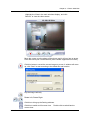
1
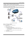
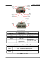
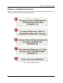
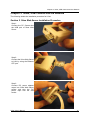
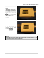
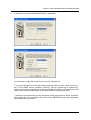
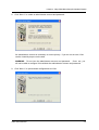
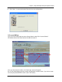
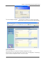
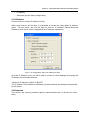
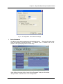
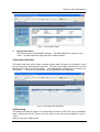
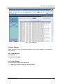
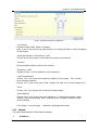
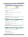
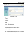
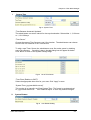
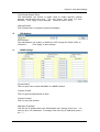
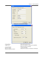
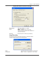
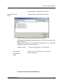
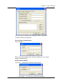
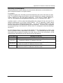
Remote Surveillance System
iView
User’s Manual
Model: LJ-738
Version 1.4
2005
CONTENTS
Chapter 1: Introduction
1
Section 1. Features
1
Section 2. iView as a Remote Surveillance System
1
Section 3. Package Contents
2
Chapter 2: Installation Procedure
4
Chapter 3: iView, USB Camera and the Network
5
Section 1. Installation Procedure
5
Chapter 4: Using iView Utility to Setup IP & Update Firmware
7
Section 1. Installing iView Utility
7
Section 2. Using iView Utility
8
2.1 Setup Wizard
9
2.2 Launch iView
13
2.3 IP Configuration
14
2.3.1 IP Address
15
2.3.2 Advanced
15
2.4 Upgrade Firmware
17
2.5 LAN Connection
19
2.6 Refresh
19
Chapter 5: iView Web Manager
20
Section 1. Introduction
20
Section 2. iView Web Manager Interface
20
2.1 Web-Camera Selection
22
2.2 Information
23
2.2.1 System Status
23
2.2.2 Current Connections
24
2.2.3 Event Log
24
2.3 Basic Settings
25
2.3.1 Camera Settings
25
2.3.2 Network
26
2.3.3 Account Settings
29
2.4 Advanced Settings
31
2.4.1 Event Notification
31
2.4.2 Motion Detection
34
2.4.3 Image Recording
37
i
2.4.4 E-mail / FTP
39
2.4.5 System Settings
41
2.4.6 Language
44
2.4.7 About
44
Chapter 6: IP2cam Multview
46
Section 1. Installing IP2cam MultiView
46
Section 2. Using IP2cam MultiView
46
2.1 Device
47
2.2 View
54
2.3 System
54
2.4 Drag-and-Drop Feature
55
Appendix A: Router Configuration
56
Appendix B: IP Address, Subnet and Gateway
74
Appendix C: Glossary
76
Chapter 1: Introduction
Chapter 1: Introduction
Section 1. Features
iView is a unique remote video surveillance system which consists of a compact
stand-alone web-server and a PAN & TILT USB PC Camera. It can be accessed from
anywhere in the world via a standard browser (IE/Netscape) by entering the IP, account and
password. Each system can simultaneously support any two combinations of USB PC
cameras be it regular or pan-tilt. With its built-in web-server, iView can stream video images
directly to the Internet without a computer. iView features a Windows-based software that
allows the user to archive streaming video directly into the hard-drive. The same software
also allows the user to monitor multiple cameras on one screen.
Web Server Features:
•
•
•
•
•
•
•
•
•
•
•
•
•
•
•
•
•
•
•
•
•
10/100Mbps fast Ethernet network access
Support any Java-Enabled Web Browser (IE/Netscape)
LCD display shows the IP address, Subnet Mask and Gateway
32-Bit RISC CPU
1MB Flash Memory
8MB Dynamic Memory
Support Up to 30 simultaneous remote viewers for each camera
Allow Up to 8 User Accounts and Passwords with different access levels
5.3V DC 1A Maximum
Operating Temperature: 0°C ~ 60°C
Operating Humidity: 10% ~ 90%
Dimensions: 48mm x 63mm x 21m
Weight: 75g
For Indoor Use. Protective housing required for Outdoor Use
Network Protocol: HTTP, TCP/IP, UDP, SMTP, PPPoE, Dynamic DNS, DNS Client,
SNTP, BOOTP, DHCP, FTP, SNMP
Support All USB PC Camera with VIMICRO ZC0301 Plus processor built-in
Resolution: 640 x 480, 320 x 240, 160 x 120.
Frame Rate: Up to 20fps in 320 x 240
MJPEG Compression
2 USB Ports for PC Cameras
USB 1.1 & 2.0 compliant
Can combine with 2 different PC Cameras
USB PC Camera (Model: LJ-738) Features
Color CMOS VGA Sensor with 380,000 pixels
PAN range 320°, TILT range 60°, Speed 90° per second
Resolution: 640x480, 320x240, 160x120
320x240 MJPEG Compression
Up to 25 frames per second
Focus Distance: 5cm to infinity, Adjustable Focus Lens
View Angle: 56∘
Auto Control: White Balance, Exposure, Color/Brightness
USB 1.1 Interface
iView User’s Manual
-1-
Chapter 1: Introduction
Section 2. iView as a Remote Surveillance System
Once iView is installed, the user can check any of the connected PC cameras using a
standard web browser. The user can monitor and control these cameras simply by entering
the IP address (set-up required with iView Utility) of the iView from anywhere in the world as
long as there is an Internet connection available.
For instance, the user can be in Paris but is able to monitor his factory production in China
and if he likes checks on his branch office located in Singapore, all this simultaneously.
Fig.1 iView Network Diagram
Section 3. Package Contents
Your iView package should contain the following items:
1.
iView Web Server,
2. PAN & TILT USB PC Camera
3. iView Application CD, which contains;
a. iView Utility: to configure IP address, update the firmware, etc.
b. IP2Cam MultiView Utility : Windows platform to monitor multiple iView.
c. User’s Manual (pdf)
d. USB PC Camera Driver (install only use as a standalone webcam)
4.
5.
5.3V DC Adapter
1 meter Ethernet Cable (RJ45)
iView User’s Manual
-2-
Chapter 1: Introduction
Fig.2 iView Front View
Fig.3 iView Back View
LED Status Indicators on iView
Light color
Signal definition
Green
Power state
On: Normal power
Error Condition
On: Error condition occurred
Red
Orange
Logon state
Yellow
USB data activity
Fig.4
Condition description
On: When there is user logon
receive the image
Flash when there is data
transmit/receive on the USB
iView Status LED Indicators
Light indicators on iView LAN Port LED
Light color
Condition description
Green
On:
lnternet correspond speed is 100M
Flash: Data transmitting/receiving
Yellow
On:
lnternet correspond speed is 10M
Flash: Data transmitting/receiving
Fig.5
iView User’s Manual
iView LAN LED Indicators
-3-
Chapter 2: Installation Procedure
Chapter 2: Installation Procedure
Before you start using iView, you will need to set-up both the hardware and software. The
following is a flow chart on the installation procedure:
Fig.6 iView installation flowchart
iView User’s Manual
-4-
Chapter 3: iView, USB Camera and the Network
Chapter 3: iView, USB Camera and the Network
The following details the installation procedure for iView.
Section 2. iView Web Server Installation Procedure
Step 1:
Connect the PC Camera into
the USB port of iView Web
Server.
Step 2:
Connect the iView Web Server
to LAN by using the Ethernet
UTP port.
Step 3:
Connect DC power adapter
output into iView Web Server
socket, and plug the DC
power input into the wall
socket
IView User’s Manual
-5-
Chapter 3: iView, USB Camera and the Network
Step 4:
The LCD will display the IP,
Subnet Mask and Gateway IP.
Use a WEB browser to login
into the iView IP address. The
icon on the LCD shows
that a USB camera is
connected.
If two USB cameras are
connected, the LCD display
will show
Warning:
Please make sure the input Voltage and Frequency of the DC power adaptor (DC 5.3V)
is correct before plugging into the power outlet!
iView User Manual
-6-
Chapter 4: Using iView Utility to Setup IP & Update Firmware
Chapter 4: Using iView Utility to Setup IP & Update Firmware
Section 1. Installing iView Utility
1.
2.
3.
Insert the enclosed iView Ap p lica tio n CD into the CD-ROM drive.
Select and open the “iView Utility” folder
Run “iViewVUT-install.exe”
a.
b.
c.
d.
iView Utility - This is a program that helps the user perform quick installation. It
will detect the current configuration and take the user thru the necessary network
setup.
Click the button to commence installation.
After installation is completed, iView Utility group will appear in Windows ’Start’
‘Program Group’
A iView Utility icon will also appear on your Window desktop
Click this to start the program
Fig.7 iView Utility Group
IP2cam MultiView - This is a window-based program designed to allow user to control a
large number of iView located either in a LAN or on a WAN.
User’s Manual - Click to read iView's User’s Manual. You will need Adobe Acrobat Reader
v5.0 or higher.
iView User’s Manual
-7-
Chapter 4: Using iView Utility to Setup IP & Update Firmware
Section 2. Using iView Utility
When you start up iView Utility, the iView Utility main menu is shown below. The selection
menu is located on the left. The Serial Number, current Firmware and IP Address of every
iView connected to the LAN will be displayed on the table to the right.
Fig.9 iView Utility Main Menu
iView User’s Manual
-8-
Chapter 4: Using iView Utility to Setup IP & Update Firmware
2.1 Setup Wizard
Use “Setup Wizard” to take you thru the basic configurations necessary to start using iView.
1.
Click to highlight the iView on the right that you want to configure.
2.
Click on “Setup Wizard”.
3.
iMView Setup Wizard will initiate to take you thru the installation.
4.
Enter the necessary camera configurations.
Choose the appropriate frequency
(Indoor 60 Hz, Indoor 50 Hz or Outdoor) to prevent flickering on the video feed. Enter a
name for the camera in the “Location” box to easily identify it.
5. Click “Next >” to configure the Network Connection.
iView User’s Manual
-9-
Chapter 4: Using iView Utility to Setup IP & Update Firmware
“Use the following IP Address”
Enter an appropriate internal IP Address, Subnet Mask and Gateway for iView (Refer to
Appendix B for an explanation of IP Addresses)
“Obtain an IP address by DHCP”
Choose this if you do not know your basic Network Configurations
“Obtain an IP address by Bootp”
Allow iView to obtain an IP address using Bootp protocol.
6.
Click “Next >” to proceed to xDSL/Cable modem setup.
This section has to be configured to allow iView to access the Internet through an
xDSL.
Select “Enable PPPoE connection” and enter your account and password details as
provided by your ISP.
Otherwise, leave it at the default “Disable PPPoE connection”
iView User’s Manual
-10-
Chapter 4: Using iView Utility to Setup IP & Update Firmware
7.
Click “Next >” to proceed with DDNS setup or registration
You will need to setup this section if you are using a Dynamic IP
If you do not already have a Domain Name registered with your ISP, select from one of
the 4 Free DDNS service providers (3322.org, dhs.org, dyndns.org or myddns.org).
Follow the link to the respective free service providers to register a Domain Name and
obtain a User Name and Password. Enter these details in the boxes provided
***However, we recommend you skip this setup at this stage and use “None” as default
Service Provider. You can always come back to this DDNS setup later after registration
with DDNS service providers.
iView User’s Manual
-11-
Chapter 4: Using iView Utility to Setup IP & Update Firmware
8. Click “Next >” to create an administrator account and password.
An administrator account is necessary to ensure privacy. If you do not set one, iView
can be viewed by anyone on the web.
WARNING: Do not lose the administrator account and password. Once set, you
will not be able to configure iView without the administrator account and password.
9. Click “Next >” to upload these configurations to iView.
iView User’s Manual
-12-
Chapter 4: Using iView Utility to Setup IP & Update Firmware
10. Click “Next >” to save and restart iView with the new configurations.
2.2 Launch iMView
Once you have finished with the above Setup Wizard, either Click “Launch iMView”
OR double click on the iView listed on the table to launch it.
Click either to Launch iView.
Once you have done the above, the iView login screen will appear.
Key in the administrator account number and password entered earlier (if you did not input
one, then just press ENTER or click on the “OK” button).
iView User’s Manual
-13-
Chapter 4: Using iView Utility to Setup IP & Update Firmware
The iView webpage will appear.
Click ActiveX for Camera A to view the video images.
(Please make sure your PC has ActiveX installed already)
2.3 IP Configuration
This section allows you to determine IP address configuration for iView.
Select the iView on the right display screen, and then click “IP Configuration”. This will bring
up the IP Address Configuration window. There are two tabs:
iView User’s Manual
-14-
Chapter 4: Using iView Utility to Setup IP & Update Firmware
•
•
IP Address
Advanced (for port setting configuration)
2.3.1 IP Address
Use this section to set the IP Address of iView.
When using iView for the first time, it is advisable to choose the “Using Static IP Address”
option. For this option, the user will have to enter an IP Address, Subnet Mask and
Gateway of their choice (refer to Appendix B for IP address explanation).
Fig.10 IP Configuration: Set an IP Address for iView
Once the IP Address is set, you will be able to connect to iView Webpage by entering this
IP Address into a standard browser.
“Obtain an IP address by DHCP or BOOTP”
The IP address, Subnet Mask and Gateway is acquired directly and assigned automatically
by the system.
2.3.2 Advanced
This section sets security password against unauthorized access to devices thru iView
Utility.
iView User’a Manual
-15-
Chapter 4: Using iView Utility to Setup IP & Update Firmware
Fig.11 IP Configuration: iView Advanced settings
i.
Device Password
Use this to set an access password to the individual device.
Once set, the user must
enter the password to access the device. In addition, the IP Address will not be
shown on the right display panel of iView Utility.
iView Utility will request for the “Input Device Password” when you click either
“Setup Wizard”, “Launch iView” or “IP Configuration”
iView User’s Manual
-16-
Chapter 4: Using iView Utility to Setup IP & Update Firmware
WARNING:
Do not lose this password. lf the password is lost, you can not access the device
To make changes.
To remove the password, you must first enter a valid “Input Device Password”, go to
“Device Password” and delete the entries, click “OK”.
ii.
Management Protocol
The administrator can determine the parameter settings when providing access via
HTTP (web) to iView. For security reasons, the administrator can choose to use
either an open or advanced port setting to control these accesses.
The default values are set to port number 80 for HTTP.
Once the HTTP port number is set to another port (other than 80), the full IP Address
must be entered in order to access the Website.
For example:
* If a value of 61 is set as the HTTP port number, then http://192.168.0.177:61
must be entered as the IP address in order to access iView website.
Uncheck to disable this function.
2.4 Upgrade Firmware
iView Utility offers a convenient method to upgrade iView firmware.
1.
Click “Upgrade Firmware” to bring up the Wizard.
Fig.12 Upgrade Firmware: Updates iView firmware
iView User’s Manual
-17-
Chapter 4: Using iView Utility to Setup IP & Update Firmware
If you have downloaded the latest firmware to your local hard drive, check
“Upgrade the iView firmware with file saved on the local hard drive” and browse to
the file location.
2.
Click “Next >” to check for the latest available firmware.
3.
Select new firmware file (*.bin) and,
4.
Click “Start”.
The iView red and yellow LED will flash alternately to indicate that firmware upgrading is
in progress. Once completed, iView will reboot.
NOTE:
If the downloading / upgrade process is interrupted or the data is corrupted,
iView will keep its default firmware to avoid complete data loss. If this happens,
repeat the above firmware upgrade procedure.
iView User’s Manual
-18-
Chapter 4: Using iView Utility to Setup IP & Update Firmware
2.5 LAN Connection
To switch to another Network Adaptor, click on “LAN Connection”.
Fig.13 Network Adaptor examined
2.6 Refresh
iView Utility automatically searches for any iView connected to the LAN. However, the
user can do a manual search by click the “Refresh” icon located at the bottom right of the
menu.
iView User’s Manual
-19-
Chapter 5: iView Web Manager
Chapter 5: iView Web Manager
Section 1. Introduction
After you have setup the hardware and set an IP address for iView, you will then be able to
go to iView web site to monitor and control the PC cameras. All you have to do is enter the
new IP address into any web browser.
1.
Start the Web Brower (Netscape or Internet Explorer)
2.
Enter the iView IP Address that was set earlier using “Setup Wizard” (e.g.
211.21.67.51), and press ENTER
3.
A login screen will appear. Enter the Administrator User Name and Password if you
have set these in the “Setup Wizard”. Otherwise, just press ENTER.
Fig.15 iView Login screen
Section 2. iView Web Manager Interface
The iView webpage main menu is divided into two sections. The selection menu on the left
and display menu on the right. The selection menu consists of the following options:
2.1 Web-Camera Selection
2.2 Information
2.3 Basic Settings
2.4 Advanced Settings
iView User’s Manual
-20-
Chapter 5: iView Web Manager
Fig.16 iView Main Menu
When using iView for the first time, you must set the following to ensure that iView works
smoothly;
a.
Set the necessary parameters in the “Configuration” menu. In particular, the
“Anti Flicker” under “Camera settings should be set to 50Hz or 60Hz
(change this to 60Hz or 50Hz /Outdoor if video output continues to flicker)
b.
Set the Light Compensation to YES
c.
Click “Apply” to confirm the setting every time you change it
d.
The USB PC Camera lens is adjusted for best results.
By default the above Camera Settings page is displayed when you login.
iView User’s Manual
-21-
Chapter 5: iView Web Manager
2.1 Web-Camera Selection
Click on either “ActiveX” or “Sun Java” from Camera
A or B to view the camera images.
By default the first USB camera connected to iView will
be denote as “Camera A”
Click “Camera B” to view camera B.
Note:
ActiveX can only function on Windows
platform and a plug-in has to be installed on the client's
computer. If this is prohibited for safety reasons you
will have to use Sun Java to view the video feed. Sun
Java also allows users who are not using Windows
based Operating System to view the video feed.
Once you click on “Camera A” the
following image will appear.
Make sure to adjust the USB camera
lens for best picture results.
Click on the controls along the Window
to control the camera.
Note:
The pan and tilt controls will only work
with cameras which have this function
built-in.
Click
to record the current image to the selected directory.
To change the saved location and filename, click
and the “Save As” window will pop up.
Choose an alternate location and filename. Click the “Save” button to confirm changes.
iView User’s Manual
-22-
Chapter 5: iView Web Manager
To change Video Codec, click
Note: The availability of Codec depends on weather the individual user has it installed on the
PC or not. Download and install Windows MediaPlayer9 to enable MPEG4 codec.
Digital Zoom In, Digital Zoom Out
Rotate Left, Rotate Right
Flip the image vertically.
Auto Pan the camera
Pan Left by 5 deg / Pan Left by 1 deg.
Pan Right by 1 deg / Pan Right by 5 deg.
Tilt Up by 5 deg / Tilt Up by 1 deg.
Tilt Down by 1 deg / Tilt Down by 5 deg.
2.2 Information
The “Information” tab contains the following subsections;
2.2.1 System Status,
2.2.2 Current Connections and
2.2.3 Event Log.
2.2.1 System Status
This section displays all the information relating to iView.
i.
System Information
This section shows iView System Information such as the Hardware and Firmware
Version, the serial number, current / local System Time, the system name, contact,
location and uptime. These values are either provided by iView or set by user.
iView User’s M anual
-23-
Chapter 5: iView Web Manager
Fig.17 iView System Status
ii.
System Information
This section shows iView Network settings. The MAC Address is unique to every
iView. All other values are set by the user in Setup Wizard.
2.2.2 Current Connections
This section will show all the users currently viewing either Camera A or Camera B. It also
lists, the login time, and total bytes received. The user has an option to block the IP or even
disable the account of any errant viewer. The administrator privilege will be required for
this feature. A total of 10 connections can be displayed at the same time.
Fig.18 iView Current Connections
2.2.3 Event Log
This section will keep a record of all events that occurred in iView. The user can Refresh,
Clear or Save the log file. There is also an option to sort the logs according to “Level” or
“Type”
iView can log up to 2,000 events
iView User’s Manual
-24-
Chapter 5: iView Web Manager
Fig.19 iView Event Log
2.3 Basic Settings
Please ensure that each of the following option is set correctly. Otherwise, iView may not
work properly.
2.3.1 Camera Settings
2.3.2 Network
2.3.3 Account Settings
2.3.1 Camera Settings
Use this section to set up the USB camera.
i.
Setting up Camera A (Similar with Camera B)
IView User’s Manual
-25-
Chapter 5: iView Web Manager
Fig.20 Individual Camera Configuration
“ Anti Flicker”
Choose between 50Hz, 60Hz or Outdoors.
Note: If you do not choose the right frequency, the image will flicker or lines will appear
on the images
“Maximum Number of Connections (1-30)”
Use this to limit the number of users that can connect to this camera.
“Location”
Enter a suitable location / name for the camera.
“Exposure (1-100)”
Set this to “Auto”, or Click “Manual” to fix the exposure.
“Light Compensation”
Choose “Yes” and iView will increase the lighting of the image. This is useful
when monitoring indoors.
Choose “No” if you do not want iView to adjust the light and view the images as is.
“Color”
Choose “Yes” for color and “No” for black and white display.
“White Balance”
Choose “Auto” to let iView make auto adjustment. To adjust this manually, select
“Manual” from the drop down menu, and then enter a suitable number for Red,
Green and Blue.
Click “Apply” to save changes.
2.3.2
Otherwise, all changes will be lost.
Network
This option determines the iView Network settings.
i.
IP Address
iView User’s Manual
-26-
Chapter 5: iView Web Manager
These items were all setup earlier in Setup Wizard.
click “Apply” to change.
Enter new addresses and
Fig.21 iView IP Address Settings
“IP Address”
This item determines iView IP Address.
“Subnet Mask”
This item sets iView Subnet Mask. The value is normally 255.255.255.0
“Gateway”
This item is to set iView Gateway.
“Obtain an IP address”
This allows the user to choose either to set iView IP Address manually or via DHCP.
iView will reboot after the above settings have been changed.
ii.
DNS Server IP
Fig.22 iView IP DNS Server IP
“Primary DNS Server IP”
This item sets iView primary DNS Server IP address.
“Secondary DNS Server IP”
This item sets iView secondary DNS Server IP address. iView will use the secondary
DNS Server IP address if the Primary DNS Server IP address is not working.
iii.
Port Number
Fig.23 iView Port Settings
“HTTP Port Number”
By default the port number is 80
“Communication to Camera Port Number” By
default the port number is 9001
iView User’s Manual
-27-
Chapter 5: iView Web Manager
iv.
Ethernet
Fig.24 iView Ethernet Settings
“Connection Type”
This item sets the communication speed between iView and the Network. iView will
reboot after “Connection Type” is changed.
v.
Dynamic DNS
Fig.25 iView Dynamic DNS Settings
“Service Provider”
The iView can be configured to register the current IP to a dynamic DNS provider.
This will enable you to locate iView’s IP every time the IP changed due to an ADSL
connection redial. Before you use this function, you will have to register with either
one of these four service providers:
•
•
•
•
•
None (Select this to disable the DDNS function)
3322.org
dhs.org
dyndns.org
myddns.com
“Domain Name”
Enter the Domain Name you have created from one of the four websites.
“Login Name”
Enter your login name for the above domain name. You only have to configure once.
“Login Password”
Enter your password. You only have to configure once.
vi.
PPPoE
Use this option to allow iView to directly dial-up using your xDSL modem and
connect to the Internet. Once set-up, iView will be able to stream the video images
directly to the Internet without going thru a IP router.
Fig.26 iView PPPoE setting
iView User’s Manual
-28-
Chapter 5: iView Web Manager
“When Connection should be made”
The user has a choice of:
Disabled
Connect always
:
:
Default setting. iView does not dial in
iView will automatically dial in.
“Login Name”
Enter your login name
“Login Password” Enter
your password
2.3.3 Account Settings
This section allows you to set up to eight (8) user accounts with different permissions for
iView.
i.
User Account
“User Name”
Determine the username of visitors who can log in. The administrator can set up to 32
case-sensitive character names.
“Password”
Set a password for the visitor’s account.
case-sensitive passwords.
The administrator can set up to 32
“Permission”
Determine the permission level to one of “Administrator”, “Operator”, “Viewer” or
“No Access”
Administrator:
Operator:
Viewer:
No Access:
This permission allows the user full access including write
permission to all the sections.
This permission level allows the user access to iView menus,
but without the permission to amend them. The administrator
can also set “Permit Hours” here for seeing camera.
This permission level allows the user to access iView at
specific time as set in “Permit Hours” for seeing camera. The
user does not have write permission and only access the
“Web Cam” and “Information” section.
This is to revoke either of the above two permission levels
given to a user and make the user account disable.
WARNING:
If you did not setup the Administrator account in Setup Wizard; you MUST now set an
Administrator permission level BEFORE setting either “Operator”, “Viewer” or “No
Access”. Failure to do so will result in you being locked out of iView Web Manager!
iView User’s Manual
-29-
Chapter 5: iView Web Manager
“IP Filter”
Visitor can only login from the IP address specified here for security consideration.
You can restrict a user access only from 192.168.1.0/24 by setting up
“192.168.1.* ”.
Otherwise, leave it as “*.*.*.*” to allow the user to login from
any place.
Fig.27 iView User Account Settings
“Max FPS”
This allows the administrator to determine the frames per second (“FPS”)
allocated to each type of account. By limiting the FPS, the administrator can
manage the limited bandwidth available. The administrator can set a figure
between 1 to 20 and unlimited FPS.
“Permit Hours”
When the Permission level is set to either “Operator” or “Viewer”, the
Administrator can configure and determine the time to which either permission
level can access the camera.
Click “Configure” to bring up the following window. You can set up to 4 different
Permit Hours (in 24hr format). Click “Apply” to save and “Close” to exit.
Fig.28 iView Permit Hours Configuration
iView User’s Manual
-30-
Chapter 5: iView Web Manager
2.4 Advanced Settings
Please ensure that each of the following option is set correctly. Otherwise, iView may not
work properly.
2.4.1 Event Notification
2.4.2 Motion Detection
2.4.3 Image Recording
2.4.4 Email / FTP
2.4.5 System Settings
2.4.6 Language
2.4.7 About
2.4.1 Event Notification
This section determines the type of event an email is sent by iView. iView can send
notifications to up to 8 email recipients. Note: You must have Administrator privilege to edit
this section.
Fig.29 iView Event Notification Page
i.
Event Notification
“Send Email”
To activate Event Notification, you will need to set “Send Email” to “Yes”. Select
“No” if you do not wish to send out any notification.
“Email Server”
A valid “Email Server” with username and password (if authentication is required) must
be made available for this feature to work. If you do not have this setup, or wish to
change the settings, click on “Edit”.
“Email Address Book”
iView User’s Manual
-31-
Chapter 5: iView Web Manager
There must be at least one valid email address in the address book. The default
email is just a sample. If you wish to add or delete entries in your address book, click
“Edit”.
“Recipients”
iView can send email notification to up to 8 valid email accounts. To add an email to
the recipient list, click
.
To remove, click
.
“Events”
This section determines the events that the selected recipients will be notified of by
email.
There are three types of events, Information, Warning and Error. Click
to select from the list of events you wish these recipients to be notified of.
Fig.30 iView Event Selection List
iView User’s Manual
-32-
Chapter 5: iView Web Manager
By default, all the events are selected; you must click “Apply” to activate them. Close
the window to return to the Event Notification Page. Click “Apply” to save your
settings.
iView will send you the following email notification depending on which event you
have selected.
Note: The image recording and motion detection notification function here will send an
email notification WITHOUT any pictures attached. For email notification with images,
the administrator has to setup the Image Recording Page and Motion Detection Page
under Advanced Settings.
Samples:
Fig.31 iView Event : Start Up
Fig.32 iView Event : User Login Details (Date, Time, Camera & IP)
iView User’s Manual
-33-
Chapter 5: iView Web Manager
Fig.33 iView Event : PPPoE Connect Successful
Fig.34 iView Event : Camera A or B Motion Detected
2.4.2 Motion Detection
This page allows the administrator to set motion detection functions for the cameras.
i.
Camera A (or Camera B)
“Enable”
To activate motion detect, the administrator has two options;
a. “Always On” or
b. “On Schedule”, the administrator can set up to 4 different time slots for motion
detection.
“Detection Sensitivity”
This will determines level of change before motion capture is triggered.
iView User’s Manual
-34-
Chapter 5: iView Web Manager
“Send image every”
Select a value between 1 to 5 seconds.
“Stop sending emails after ## email(s) or image idle for ## second(s)”
iView will stop sending on the lower of the two conditions.
You can set between
1, 3, 5, 7 and 10 seconds. Emails can be set from 1 to 99999 pieces, or 0 for stop
sending email only when image idle occurred.
“Schedule”
If set to “On Schedule” in the above section, the administrator can then input the four
preferred schedule time slots for motion detection. Time must be entered in 24hr
format.
Fig.35 iView Motion Detection Page
“Send to FTP Server”
This option allows the administrator to send and store the motion- detected images
on a FTP site. This is useful for future reference and recording purpose. Click “Yes” to
activate.
“ftp://<empty>/<folder>”
This box allows the administrator to determine the file location within the FTP
site. If you have not entered a FTP server, the above will be left <empty>.
iView User’s Manual
-35-
Chapter 5: iView Web Manager
To setup the FTP server, click “Edit” to go to the Email / FTP Page. Once you have
entered the FTP server, login name and password, click “Apply” and then Click on
“Motion Detect” to return here.
Enter a directory or folder name in <folder>.
Click “Apply” when done.
“System Defined / User Defined”
The administrator can also determine to either have the system automatically assign
the filenames for the pictures saved. Or assign these filenames.
“Filename”
Give the motion detected JPG images a standard filename prefix, to be followed by
looping number suffix.
“Loop from ## to ##”
This will determine the number of suffixes preceding the above filename. Once the
last number is reached, the first file will be replaced by the most current image.
“Digits”
This will determine the number of digits assignable for the above number suffix. The
administrator can choose to assign between 1 to 6 digits.
Click
for an example.
“Send Email”
To send an email notification of Motion Detection with image, choose “Yes”,
otherwise, choose “No”
iView User’s Manual
-36-
Chapter 5: iView Web Manager
Fig.36 iView Motion Detect Email Notification
“Email Server”
The administrator will have to set this up. Otherwise, click “Edit” to go to the Email
/ FTP Page to make the necessary configuration. Click on Motion Detection to return
here.
“Recipient” & “Email Address Book”
The administrator can determine who shall receive email notification. To add to the
recipient list, either double click on the email in the address book or click
. To add all the email address at once, click
, or
Click
.To remove an entry click
to remove all entries from the recipient list.
to confirm and save the above settings.
2.4.3 Image Recording
Image recording allows the user to receive an image to either their email account or to a FTP
server.
The images will be sent over a predetermined interval and a certain period.
iView User’s Manual
-37-
Chapter 5: iView Web Manager
Fig.37 iView Image Recording Page
i.
Camera A (or Camera B)
“Begin – End (hh:mm)”
The administrator can determine up to 2 time slots when Image Recording is active.
The time is in 24hrs format.
“Send image every ## minute(s)”
The administrator can determine the exact interval at which iView capture and send an
image. Choose among 1, 3, 5, 7 and 10 minutes.
“Send to FTP Server” & “Send Email”
This is similar to the function available in Motion Detection Page. Please refer to section
2.4.2 for details.
iView User’s Manual
-38-
Chapter 5: iView Web Manager
Fig.38 iView Email of Image Recorded
2.4.4
E-mail / FTP
This section sets up the necessary Email and FTP server information. The administrator will
have to enter a valid Account Name and Password to the Email server and/or FTP server.
This information is necessary to allow email notification and ftp file sending features in
Advanced Settings.
iView User’s Manual
-39-
Chapter 5: iView Web Manager
Fig.39 iView Email / FTP Page
i.
FTP Settings
“FTP Server”
The administrator will have to enter the FTP server address here.
“Account Name”
Enter the FTP account name here
“Password”
Enter the corresponding password.
Click “Apply” to save the above settings.
ii.
Email Settings
“E-mail Server”
The administrator will have to enter the Email server address here.
“Sender’s Email Address”
This will determines iView’s Email address.
“Email Server Requires Authentication”
If set to “YES”, the administrator will have to provide the account name and password
in order to access the Email server. Otherwise, enter “NO”.
iView User’s Manual
-40-
Chapter 5: iView Web Manager
“Account Name”
Enter the account name or login name to the Email server.
“Password”
Enter the password for the above account name.
Click “Apply” to save the above changes.
iii.
Email Address Book
Fig.40 iView E-mail Address Book Entry
Enter an Email address in the box provided and click “Add Email Address”. The
new email address will be added to the list.
The administrator can store up to 20
email addresses here.
To delete an Email address, just press “Delete”.
2.4.5 System Settings
This page allows the administrator to set iView SNMP settings so it can be used by a NMS
(Network Management System) like IP2cam MultiView.
iView User’s Manual
-41-
Chapter 5: iView Web Manager
i.
System Time
Fig.41 System Time
“Time Between Automatic Updates”
The administrator can set an interval for time synchronization. Select either 1, 3,12 hours
or 1, 10 & 30 days.
“Time Server”
Choose the nearest Time Server to your iView location. The administrator can choose
from the list of a maximum of 30 Time Servers.
To add a new Timer Server the administrator must first make space by deleting
some Time Servers. Once this is done, the add dialog box will appear as below.
Click “Back” to return to the System Settings Page.
Fig.42 List of Time Server
“Time Zone (Relative to GMT)”
Select the appropriate time zone for your area. Click “Apply” to save.
“System Time (yyyy/mm/dd hh:mm:ss)”
This section is to manually set iView System Time. The format is pre-determined
to: yyyy/mm/dd hh:mm:ss. Click “Manual Adjust” to save any manual changes.
ii.
System Restart
Fig.43 Auto Restart Setting
iView User’s Manual
-42-
Chapter 5: iView Web Manager
“Auto Restart System Every”
The administrator can choose to restart iView at certain intervals (choose
between minutes and hours only). This will ensure that iView will work
smoothly. Click “Apply” to save changes. Default is set as 5 hours.
“Manual Restart”
Click “Restart Now” to restart the system immediately.
iii.
LED Settings
“LED function”
The administrator can enable or disable the LED (except the Power LED) on
iView here.
Click “Apply” to save settings.
iv.
SNMP Settings
”System Name”
This is to give iView a name identifiable in a SNMP network.
“System Contact”
This is to give the administrator a name.
“System Location”
This is to set iView location.
“Manager IP Address”
This set the IP address where the administrator can manage iView from. It is
valid for up to 8 IP addresses. To manage iView from any IP addresses leave it
as *.*.*.*.
iView User’s Manual
-43-
Chapter 5: iView Web Manager
“Community”
This is to set a Community name for NMS. The community name has to be the same as
that set in NMS.
“Permission”
This is to set the administrator’s authority. Options are Read, Read/Write, and
No Access.
“Description”
This is for an administrator to make notes.
2.4.6 Language
Use this section is to set iView Interface language.
i.
Interface Language
At the moment, the administrator can only choose between; English, Chinese
(Traditional) and Chinese (Simplified).
ii.
Email Preference
Click “Yes” to apply language interface to Email notification.
2.4.7 About
The administrator can use this section to check firmware information, save/restore settings,
upgrade firmware and see manufacturer’s details.
i.
About
This section gives crucial information about iView’s Firmware Version, Hardware
Version and Serial Number. These are required information for service calls.
iView User’s Manual
-44-
Chapter 5: iView Web Manager
ii.
Save / Restore Settings
“Save current Configuration”
Click “Save” to save the current settings and configuration to your PC. The text file will
have a default format of YYYY_MMDD_####.cfg. The administrator can change
this, if necessary.
“Restore previous configuration”
This function is only available if a setting has been saved initially. Browse to the
location where the file is saved and click “Restore”
“Reset to factory default”
This function will reset all settings to its default value.
Fig.44 iView About Page
“Upgrade Firmware”
Click to check for the latest firmware.
install the latest firmware
iView will automatically download and
Fig.45 iView checking for latest firmware to upgrade
iView User’s Manual
-45-
Chapter 6: IP2cam MultiView
Chapter 6: IP2cam MultiView
IP2cam MultiView is a program to manage multiple iViews in a network. It is able to
detect the IP’s of all the iViews Web Servers installed, and display them in a list form for
easy management.
Section 1. Installing IP2cam MultiView
1. Select and open the “IP2cam Multview” folder on the CD-ROM
2. Run “IP2cam Multview utility.exe” and follow the installation wizard
3. After installation, there will be a “IP2cam” group in the Windows Start group and a IP2cam
Multiview
icon on your desktop
4. Click “IP2cam Multview” to start using the program.
Section 2. Using IP2cam MultiView
After the IP2cam MultiView program start up the following main windows will be displayed.
iView User’s Manual
-46-
Chapter 6: IP2cam MultiView
2.1 Device
:
:
Start iMultiView and press the “Enumerate” button, iMultiView will
start a search for all the iView on network and list them in the main
window.
Manually adds the iView to be monitored. Enter the assigned iView
IP Address. Port Number by default is 9001. You will have to
enter the account and password if one has been set earlier.
Otherwise just press “OK”.
Once detected, the following will show in the main window:
This shows that the camera is online and active.
This shows that the camera is off-line
:
Highlight the iView to be deleted from iMultiView’s list. Click
“Yes” to confirm deletion of selected iView.
:
Display the General iView settings. Key in a Host Name and
Location for the camera.
iView User’s Manual
-47-
Chapter 6: IP2cam MultiView
Display the current Camera settings.
Camera Select:
Image Zoom:
Select either camera A or B
Resize the window to between 25% and 200%
Camera Rotation:
Mirror the Image:
Maximum frame per second:
Rotate the image if necessary
To mirror the image.
Select from 0.01 fps to a maximum of 30.00 fps
iView User’s Manual
-48-
Chapter 6: IP2cam MultiView
Display the Motion Detection Settings.
Click the checkbox to enable
Motion Detection.
Note:
This function requires the
Camera Window be active. Click “Monitor” to
activate the Window.
Enable Motion
Detect:
Sensitivity:
Choose from 0% to 100% (very sensitive)
Image Recording
Click Start Recording when Motion Detected to enable the feature.
Click the “Details” button for the following option;
Image
Compression:
iView User’s Manual
Choose from the list of available compressions.
Note: This list is dependent on the Codec
-49-
Chapter 6: IP2cam MultiView
that is available / installed on the local PC.
Recording AVI File
Path
Location where the file will be recorded to.
Recorded files are save using the following file extension;
CMV[year][month][date][hour][minute][seconds]. The time here denote the
record start time.
Note: Use the “Detail View” to check the record stop time. You can change
the display view or add a new folder here.
Stop after idle for:
Send AVI file
Notification by
Email:
Set the value between 1 to 100 seconds
Send an AVI file via email in the event any
motion is detected.
Configure Settings for Email Notification
iView User’s Manual
-50-
Chapter 6: IP2cam MultiView
You will need to configure the “Message Sender Information”
in order for iView to send emails.
Server Require Authentication
Click “settings…”
Enter your Account Name and Account Password if your Server
Requires Authentication.
Notified Email Address
Click “Add…” and enter a new Email address below
Click “Modify…” to modify the entered Email Address
iView User’s Manual
-51-
Chapter 6: IP2cam MultiView
Click “Delete” to remove an email address from the notification list.
:Highlight the iView in the main windows display, and click
“Monitor” to view the video stream.
Move the curser over the edges of the picture and it will turn into an arrow.
Click and hold to pan / tilt the camera (if the camera supports this function)
Click this button to record the current image on screen. A window will come
up, click “Start” to start recording to the default file and location.
Flip the image vertically
Rotate Left, Rotate Right
,
Click this to bring up the Setting windows.
Click this to switch to full screen view.
current view.
iView User’s Manual
Double click to switch back to
-52-
Chapter 6: IP2cam MultiView
Click and drag to resize the window and it’s contents.
Click the left side of the viewing window to bring out more control
features.
Clicking once will cause the camera to pan left by 1 deg.
Click and hold and the camera will pan increasingly faster to the left.
Clicking once will cause the camera to pan right by 1 deg.
Click and hold and the camera will pan increasingly faster to the left.
Click once to tilt the camera up by 1 deg.
Click and hold and the camera will tilt increasingly faster upwards.
Click once to tilt the camera down by 1 deg.
Click and hold and the camera will tilt increasingly faster downwards.
Auto Pan (if camera which support this function)
iView User’s Manual
-53-
Chapter 6: IP2cam MultiView
2.2 View
:
Switch between Large or Small icon view
Large icon display
Small icon display
2.3 System
: Display the Event Log (IP address, Port, date, Time, description of
event) of the selected iView.
:
iView User’s Manual
Set the SNMP Parameter.
-54-
Chapter 6: IP2cam MultiView
2.4 Drag-and-Drop Feature
IP2cam MultiView also feature a “Drag-and-Drop to Desktop” feature. Double click
the icon on your desktop to view the images immediately. Useful if you are
monitoring multiple cameras at a time.
Step 1:
Select the camera
location of your choice.
Step 2:
Left click, hold and drag
it onto the desktop.
Step 3:
Release the mouse
button anywhere on
the desktop and a
new desktop icon is
created there.
Step 4:
Double click on the icon
on the desktop, to view
the images.
iView User’s Manual
-55-
Appendix A: Router Configuration
Appendix A: Router Configuration
The following section describes the initial configuration of the router and port forwarding for
your router.
If your router is not listed here, please refer to the manufacturer’s website
for assistance with configuring your router to work with iView.
Port Forwarding for iView
iView requires certain ports to be open on your router to allow other computers on the
Internet to “see” it on your internal network. Normally, your router will have the less common
ports disabled or blocked by the router’s built-in firewall. In order for the iView applications to
work properly and not be blocked, the firewall settings need to be configured. In each
instance there will be a trigger port and incoming port(s), where traffic on the trigger port
tells the Firewall to open the incoming ports. The iView require that TCP Port 80 and UDP
9001 (default settings) be opened to the Internet. TCP Port 80 is used for accessing the
camera’s homepage and UDP Port, where 9001 is used for authentication and video
streaming.
If your Internet service Provider blocks port 80/9001, you’ll need to reconfigure your camera
and router to other ports such as 81/9002, 82/9003, etc. To change the port settings on the
camera, you’ll need to use iView Utility.
Follow the steps below to configure your router, depending on the router manufacturer and
model. If your particular router manufacturer or model is not listed below, please contact your
router manufacturer for further assistance in configuring the router.
The Following Router manufacturers and models are included in this document:
Description
Brand
Model
3Com
3C857-US
3CRWE52196
OfficeConnect Cable/DSL Gateway
OfficeConnect Wireless Cable/DSL Gateway
Belkin
F5D6230-3
F5D7230-4– 54g
DI-604/DI–614+/DI-624
DI-704/704P
DI714
DI-714P+
TrueMobile 2300
Wireless BroadbandRouter
Wireless Cable/DSL Gateway Router
Wireless DSL/Cable gateway Router
BEFSR41
BEFSX41
EtherFast Cable/DSL Router
Instant Broadband EtherFast
Cable/DSL Firewall Router with 4-Port
Switch/VPN EndPoint
Wireless Access Point Router with 4-Port
Switch – Version 2
D-Link
Dell
Linksys
BEFW11S4
Microsoft
MN-100
MN-500
iView User’s Manual
-
Wired Base Station
Wireless Base Station
-56-
Appendix A: Router Configuration
NETGEAR
Proxim
Siemens
SMC
RP614
MR814
MR314
FVS318
ORiNOCO BG-2000
Broadband Gateway
SpeedStream 2602
SpeedStream 2623
SpeedStream 2604
SpeedStream 2624
Web Safe Router
Wireless Router
Cable/DSL Wireless Router
ProSafe VPN Firewall
-
SMC2404WBR
Barricada Turbo 11/22Mbps Wireless
Cable/DSL Broadband Router
Barricada Cable/DSL Broadband Router
Barricada Wireless Cable/DSL Broadband
Router
Barricade 4-port 11Mbps Wireless
Broadband Router
SMC7004VBR
SMC7004CWBR
MC7004AWBR
iView User’s Manual
2-Port DSL/Cable Router
Wireless DSL/Cable Router
4-port DSL/Cable Router
Wireless DSL/Cable Router
-57-
Appendix A: Router Configuration
3Com (http://www.3com.com)
3C857-US – OfficeConnect Cable/DSL Gateway
3CRWE52196 – OfficeConnect Wireless Cable/DSL Gateway
1. Log into your router.
2. On the main page, select Firewalls on the left side of the page.
3. Select the Virtual Servers tab at the top of the page.
4. Click New on the right side of the page to open the Virtual Server Settings dialog box.
5. Type in the camera’s IP address in the Server IP address text box. (Look on the iView IP
address LCD display for the last 3 digits of the camera’s IP address.)
6. Under Local Service, select Custom.
7. Under Custom Service Name, type in: iView.
8. Under Specify Custom Service Ports, type in: 80, 9001.
9. Click Add to save the settings. The iView should now be configured to work with your
router and be accessible from the Internet.
iView User’s Manual
-58-
Appendix A: Router Configuration
Belkin (http://www.belkin.com)
F5D6230-3 – Wireless Cable/DSL Gateway Router
1. Log into your router.
2. On the main page, select Virtual Server on the left side of the page under the
Security section.
3. Enter the following information on the page:
Line #1:
Private IP:
Type in the camera’s IP address (Look on the iView IP
Address LCD display for the last 3 digits of the camera’s IP
address)
Private Port:
80
Type:
TCP
80
Public Port:
Line #2
Private IP:
Private Port:
Type:
Public Port:
Type in the camera’s IP address (Look on the iView IP
Address LCD display for the last 3 digits of the camera’s IP
address)
9001
UDP
9001
4. Click Enter to save the settings. The iView should now be configured to work with your
router and be accessible from the Internet.
F5D7230-4 – 54g Wireless DSL/Cable gateway Router
1. Log into your router.
2. On the main page, select Firewall on the left side of the page.
3. Under Firewall, select Virtual Servers.
4. Enter the following information on the page:
Line #1
Enable:
Checked in
Description:
iView – Webpage
Internet Port:
80 to 80
Type:
Private IP address:
iView User’s Manual
TCP
Type in the camera’s IP address. (Look on the iView Address LCD
display for the last 3 digits of the camera’s IP address)
-59-
Appendix A: Router Configuration
Private Port
80 to 80
Line #2
Enable:
Description:
Internet Port:
Checked in
iView – Camera
9001 to 9001
Type:
Private IP address:
Private Port
UDP
Type in the camera’s IP address (Look on the iView Address LCD
display for the last 3 digits of the camera’s IP address)
9001 to 9001
5. Click Apply Changes to save the settings. The iView should now be configured o
work with your router and be accessible from the Internet.
iView User’s Manual
-60-
Appendix A: Router Configuration
D-Link (http://www.dlink.com)
DI-604/DI – 614+/DI-624
1. Log into your router
2. On the main page, click on Advanced at the top of the page.
3. On the left side of the page, click on Virtual Server. Note: Make sure DMZ host is
disabled. If DMZ is enabled, it will disable all Virtual Server entries.
4. Enter the following information on the page:
Enable/Disable:
Enabled
Name:
Private IP:
Protocol Type:
Private Port:
iView - Webpage
Type in the camera’s IP address, for example: 192.168.0.5
TCP
80
Public Port:
Schedule:
80
Always
5. Click Apply to save the settings.
6. Enter the following information on the page:
Enable/Disable:
Enabled
Name:
Private IP:
Protocol Type:
Private Port:
iView - Webpage
Type in the camera’s IP address, for example: 192.168.0.5
UDP
9001
Public Port:
Schedule:
9001
Always
7. Click Apply o save the settings. iView should now be configured to work with your router
and be accessible from the Internet.
DI-704/704P
1. Log into your router
2. On the main page, click on Advanced at the top of the page.
3. On the Virtual Server page, enter the following information; For
ID#1:
Service Port:
Service IP:
iView User’s Manual
80
Type in the camera’s IP address, for example: 192.168.0.5
-61-
Appendix A: Router Configuration
Enabled/Disabled:
Enabled
For ID#2
Service Port:
Service IP:
Enabled/Disabled:
9001
Type in the camera’s IP address, for example: 192.168.0.5
Enabled
4. Save your settings. iView should now be configured to work with your router and
be accessible from the internet.
DI714
1. Log into your router
2. On the main page, click on Advanced at the top of the page.
3. Click on Virtual Server Settings on the left side of the page.
4. Enter the camera’s IP address into the Internal IP field. Under Service, select All and then
click Submit to save your settings. iView should now be configured to work with your router
and be accessible from the internet.
DI-714P+
1. Log into your router
2. On the main page, click on Advanced at the top of the page.
3. On the left side of the page, click Virtual Server.
4. Enter the following information on the page:
For ID#1:
Service Port:
Service IP:
Enabled/Disabled:
80
Type in the camera’s IP address, for example: 192.168.0.5
Enabled
For ID#2
Service Port:
Service IP:
Enabled/Disabled:
9001
Type in the camera’s IP address, for example: 192.168.0.5
Enabled
5. Click Apply to save your settings. iView should now be configured to work with your
router and be accessible from the internet.
iView User’s Manual
-62-
Appendix A: Router Configuration
Dell (http://www.dell.com)
TrueMobile 2300 Wireless Broadband Router
1. Log into your router
2. On the main page, click on Advanced Settings at the top of the page.
3. Go to the Port Forwarding section and select Custom Port Forwarding Settings.
4. Check the Enable box.
5.
Enter the desired name or description in the Service Name field such as iView Web.
6. In the Incoming Ports field, specify port 80 in both boxes.
7. In the Destination IP Address field, enter the IP address of iView
8. In the Destination MAC Address field, enter the MAC address of iView. You can find the
camera’s MAC address by either looking at the MAC address sticker on the bottom of the
camera or by utilizing iView setup utility to display the MAC address.
iView User’s Manual
-63-
Appendix A: Router Configuration
Linksys (http://www.linksys.com)
BEFSR41 – EtherFast Cable/DSL Router
BEFSX41 – Instant Broadband EtherFast Cable/DSL Firewall Router with 4-Port
Switch/VPN EndPoint
BEFW11S4 – Wireless Access Point Router with 4-Port Switch – Version 2
1. Log into your router
2. On the router’s main page, click on Advanced at the top of the page.
3. On the next page, click on Forwarding.
4. Enter the following information on the page:
Line #1:
Customized Applications:
Ext. Port:
Protocol:
IP Address:
Enable:
Line #2:
Customized Applications:
Ext. Port:
Protocol:
IP Address:
Enable:
iView – Webpage
80 to 80
TCP
Type in the camera’s IP address, for example:
192.168.0.5
Checked in
iView – Camera
9001 to 9001
UDP
Type in the camera’s IP address, for example:
192.168.0.5
Checked in
5. Click on Apply to save the settings. iView should now be configured to work with your
router and be accessible from the Internet.
iView User’s Manual
-64-
Appendix A: Router Configuration
Microsoft (http://www.microsoft.com/hardware/broadbandnetworking)
MN-100 – Wired Base Station
MN-500 – Wireless Base Station
1. Log into your router
2. Open the Bass Station Management Tool, and then click Security.
3. On the Security menu, click Port Forwarding, and then click Set up persistent port
forwarding.
4. In the Enable checkbox, check in the checkbox.
5. In the Description box, type a description of the server field such as: iView Web.
6. In the Inbound port boxes, type in: 80 – 80. (i.e. from Port 80 to Port 80)
7. In the Type box, select the protocol as TCP.
8. In the Private IP address box, type in the IP Address of the iView network camera. For
example, type in: 192.168.0.5.
9. In the Private port boxes, these values are automatically filled in from Step 6 and should
already show 80 – 80.
10. On the next empty line, repeat steps 4-9, except this time the Description should be iView
Cam and the Inbound/Private port boxes should be 9001 – 9001 (UDP). The protocol and
private IP address should be the same.
11. Click Apply to save the changes you have made. iView should now be configured to
work with your router and be accessible from the Internet.
iView User’s Manual
-65-
Appendix A: Router Configuration
NETGEAR (http://www.netgear.com)
RP614 – Web Safe Router
MR814 – Wireless Router
1. Log into your router.
2. Click Advanced -> Port Forwarding on the left side of the page.
3. Click Add Customer Service.
4. Enter the following information on the page:
Service Name:
iView – Web
Starting Port:
80
Ending Port:
Server IP Address :
80
Type in the camera’s IP address, for example:
192. 168. 0. 5
5. Click Apply to save the settings.
1. Enter the following information on the page:
Service Name:
iView – Cam
Starting Port:
9001
Ending Port:
Server IP Address:
9001
Type in the camera’s IP address, for example:
192.168.0.5
7. Click Apply to save the settings. iView should now be configured to work with your router
and be accessible from the internet.
MR314 – Cable/DSL Wireless Router
1. Log into your router.
2. Click Advanced on the left side of the page.
3. Click Ports.
4. Enter the following information on the page:
Line #1:
Starting Port:
Ending Port:
Server IP Address:
iView User’s Manual
80
80
Type in the camera’s IP address, for example:
192.168.0.5
-66-
Appendix A: Router Configuration
Line #2:
Starting Port:
Ending Port:
Server IP Address:
9001
9001
Type in the camera’s IP address, for example:
192.168.0.5
5. Click Apply to save the settings. iView should now be configured to work with your router
and be accessible from the internet.
FVS318 – ProSafe VPN Firewall
1. Log into your router.
2. On the main page, click on Add Service on the left side of the screen.
3. Click Add Customer Service.
4. In the Name field enter a name for the camera, for example:
iView Web:
Type:
TCP
Start Port:
Finish Port:
81
81
5. Click Apply to save the settings.
6. There is a bug in the NETGEAR FVS318 1.4 firmware that does not record any entry that
uses port 80. If you intend to use port 80, you will initially need to enter 81 for the Start and
Finish port, and then edit the entry to port back to 80. Click on Add Service on the left side
of the screen.
7. In the Service Table window select iView Web and click Edit Service.
8. Change the Start and Finish port to 80. Click Apply.
9. On the main page, click on Add Service on the left side of the screen and then click Add
Custom Service. In the Name field enter a name for the camera, for example: iView Cam.
Type:
UDP Start
Port:
9001
Finish Port:
9001
10. Click Apply to save the settings.
11. On the main page, click on Ports at the side of the screen.
A. Click Add.
B. For Service Name select: iView Web
C. Action: ALLOW always
iView User’s Manual
-67-
Appendix A: Router Configuration
D. Local Server Address: Enter the IP address of the camera
E. WAN Users Address: Any
F. Click Apply.
12. Click Add again.
A. For Service name select: iView Cam
B. Action: ALLOW always
C. Local Server Address: Enter the IP address of the camera
D. WAN Users Address: Any
E. Click Apply.
13. Exit the router setup program. iView should now be configured to work with your router
and be accessible from the internet.
iView User’s Manual
-68-
Appendix A: Router Configuration
Proxim (http://www.proxim.com)
ORiNOCO BG-2000 Broadband Gateway
1. Log into your router.
2. On the router’s main page, click on Setup at the top of the page.
3. On the left side of the page, click on Advanced settings -> Port Forwarding.
4. Check in the checkbox for Enable Port Forwarding.
5. Click New on the right side of the page.
6. Enter the following information on the page:
Global Port:
80
Local Address:
Local Port:
Type:
Type in the camera’s IP address, for example:
192.168.0.5
80
TCP
7. Click Save to save the settings.
8. Click New on the right side of the page.
9. Enter the following information on the page.
Global Port:
9001
Local Address:
Local Port:
Type:
Type in the camera’s IP address, for example:
192.168.0.5
9001
UDP
10. Click Save to save the settings.
11. Click Restart on the left side of the page to restart your router. iView should now be
configured to work with your router and be accessible from the internet.
iView User’s Manual
-69-
Appendix A: Router Configuration
Siemens (http://www.speedstream.com) SpeedStream
2602 – 2-Port DSL/Cable Router SpeedStream 2623 –
Wireless DSL/Cable Router SpeedStream 2624 –
Wireless DSL/Cable Router
1. Log into your router.
2. After you have logged in, click on Advanced Setup -> Virtual Servers.
3. Enter the following information on the page:
Line #1:
Private IP:
Type:
Public Port:
Line #2
Private IP:
Type:
Public Port:
Type in the camera’s IP address, for example:
192.168.0.5 (Look at iView’s IP Address LCD display for
the last 3 digits of the camera’s IP address) Private Port: 80
TCP
80
Type in the camera’s IP address, for example:
192.168.0.5 (Look at iView’s IP Address LCD display for the
last 3 digits of the camera’s IP address) Private Port: 9001
UDP
9001
4. Click Enter to save the settings. iView should now be configured to work with your router
and be accessible from the Internet.
SpeedStream 2604 – 4-port DSL/Cable Router
1. Log into your router.
2. After you are logged in, click on Advanced Setup -> Virtual Servers.
3. Under the Properties section, there are a few entries you’ll need to add. Check in the
checkbox for Enable.
4. Under the first box, next to the Enable checkbox, type in: iView Web.
5. Under PC (Server), select your camera or the camera’s IP address from the list. If the
camera is not listed, select the link titled “My PC is not listed.”
6. Leave Protocol as TCP.
iView User’s Manual
-70-
Appendix A: Router Configuration
7. Under Internal Port No type in: 80
8. Under External Port No type in: 80
9. Click on Add to save these settings.
10. Under the first box, next to the Enable checkbox, type in: iView Cam.
11. Under PC (Server), select your camera or the camera’s IP address from the list. If the
camera is not listed, select the link titled “My PC is not listed.”
12. Leave Protocol as TCP.
13. Under Internal Port No type in: 9001
14. Under External Port No type in: 9001
15. Click on Add to save these settings. iView should now be configured to work with your
router and be accessible from the Internet.
iView User’s Manual
-71-
Appendix A: Router Configuration
SMC (http://www.smc.com)
SMC2404WBR – Barricada Turbo 11/22Mbps Wireless Cable/DSL Broadband
Router
SMC7004VBR – Barricada Cable/DSL Broadband Router
SMC7004CWBR – Barricada Wireless Cable/DSL Broadband Router
1. Log into your router.
2. After you are logged in, click NAT on the left side of the page.
3. Click on Virtual Server on the left side of the page.
4. Enter the following information on the page:
Line #1:
Private IP:
Type:
Public Port:
Line #2
Private IP:
Type:
Public Port:
Type in the camera’s IP address, for example:
192.168.0.5 (Look at iView’s IP Address LCD display for
the last 3 digits of the camera’s IP address) Private Port: 80
TCP
80
Type in the camera’s IP address, for example:
192.168.0.5 (Look at iView’s IP Address LCD display for the
last 3 digits of the camera’s IP address) Private Port: 9001
UDP
9001
5. Click Apply to save the settings. iView should now be configured to work with your router
and be accessible from the Internet.
SMC7004AWBR – Barricade 4-port 11Mbps Wireless Broadband Router
1. Log into your router.
2. Click on Virtual Server on the left side of the page.
3. Enter the following information on the page:
For ID #1:
Service Port:
Private IP:
iView User’s Manual
80
Type in the camera’s IP address, for example:
192.168.0.5 (Look at iView’s IP Address LCD display for the
last 3 digits of the camera’s IP address) Enable: Checked in
-72-
Appendix A: Router Configuration
For ID #2:
Service Port:
Private IP:
9001
Type in the camera’s IP address, for example:
192.168.0.5 (Look at iView’s IP Address LCD display for the
last 3 digits of the camera’s IP address) Enable: Checked in
4. Click Save to save the settings. iView should now be configured to work with your router
and be accessible from the Internet.
iView User’s Manual
-73-
Appendix B: IP Address, Subnet and Gateway
Appendix B: IP Address, Subnet and Gateway
This section discusses Communities, Gateways, IP Addresses and Subnet masking
Communities
A community is a string of printable ASCII characters that identifies a user group with the
same access privileges. For example, a common community name is “public.” For
security purposes, the SNMP agent validates requests before responding.
The agent
can be configured so that only trap managers that are members of a community can send
requests and receive responses from a particular community. This prevents unauthorized
managers from viewing or changing the configuration of a device.
Gateways
Gateway, also referred to as a router, is any computer with two or more network adapters
connecting to different physical networks. Gateways allow for transmission of IP packets
among networks on an Internet.
IP Addresses
Every device on an Internet must be assigned a unique IP (Internet Protocol) address. An
IP address is a 32-bit value comprised of a network ID and a host ID. The network ID
identifies the logical network to which a particular device belongs. The host ID identifies
the particular device within the logical network. IP addresses distinguish devices on an
Internet from one another so that IP packets are properly transmitted.
IP addresses appear in dotted decimal (rather than in binary) notation. Dotted decimal
notation divides the 32-bit value into four 8-bit groups, or octets, and separates each
octet with a period. For example, 199.217.132.1 is an IP address in dotted decimal
notation.
To accommodate networks of different sizes, the IP address has three divisions –
Classes A for large, B for medium and C for small. The difference among the network
classes is the number of octets reserved for the network ID and the number of octets
reserved for the host ID.
Class
A
B
C
1-126
128-191
192-223
Network lD
First octet
First two octets
First tree octets
Host lD
Last three octets
Last two octets
Last octet
Number of Hosts
16,387,064
64,516
254
Any value between 0 and 255 is valid as a host ID octet except for those values the InterNIC
reserves for other purposes
Value
0.255
127
224-254
iView User’s Manual
Purpose
Subnet masking
Loopback testing and interprocess communication on local devices
IGMP multicast and other special protocols.
-74-
Appendix B: IP Address, Subnet and Gateway
Subnetting and Subnet Masks
Subnetting divides a network address into sub-network addresses to accommodate more
than on physical network on a logical network.
For example:
A Class B company has 100 LANs (Local Area Networks) with 100 to 200 nodes on each
LAN. To classify the nodes by its LANs on one main network, this company segments the
network address into 100 sub-network addresses. If the Class B network address is
150.1.x.x, the address can be segmented further from 150.1.1.x through 150.1.100.x
A subnet mask is a 32-bit value that distinguishes the network ID from the host ID for
different sub-networks on the same logical network. Like IP addresses, subnet masks
consist of four octets in dotted decimal notation. You can use subnet masks to route and
filter the transmission of IP packets among your sub-networks. The value “255” is assigned
to octets that belong to the network ID, and the value “0” is assigned to octets that belong to
the host ID.
For the example above, if you want all the devices on the sub-networks to receive each
other’s IP packets, set the subnet mask to 255.255.0.0.
If you want the devices on a single
sub-network only to receive IP packets from other devices on its own sub-network, set the
subnet mask to 255.255.255.0 for the devices on the sub-network.
Subnet Mask
0.0.0.0
255.0.0.0
255.255.0.0
255.255.255.0
iView User’s Manual
Routing and Filtering
IP packets are transmitted to all devices.
IP packets are only transmitted to devices that are IP that’s first octet
matches the sender’s IP address’s first octet.
IP packets are only transmitted to devices that are IP that’s first two octets
match the sender’s IP address’s first two octets.
IP packets are only transmitted to devices that are IP that’s first three octets
match the sender’s IP address’s first three octets.
-75-
Appendix C: Glossary
Appendix C: Glossary
The Glossary section defines the terms used in this User’s Manual
Term
Definition
Local Area Network technology, originally developed by Xerox
Corporation, can link up to 1,024 nodes in a bus network. Ethernet
provides raw data transfer in a rate of 10 megabits/sec. with actual
throughputs in 2 to 3 megabits/sec. using a baseband (single-channel)
Ethernet communication technique. Ethernet uses carrier sense multiple access
collision detection (CSMA/CD) that prevents network failures when two
devices attempt to access the network at the same time LAN hardware
manufacturers use Ethernet protocol; their products may not be
compatible.
A computer that attaches to a number of networks and routes packets
Gateway between them. The packets can be different protocols at the higher
levels.
Internet Protocol – The TCP/IP standard protocol defines the IP
IP
datagram as the unit of information passed across a network.
Internet Protocol Address – A 32-bit address assigned to hosts
participating in a TCP/IP network. The IP address consists of network
IP Address
and host portions. It is assigned to an interconnection of a host to a
physical network.
Medium Access Control - The network layer between the physical and the
data link layers. Specifically, the physical (hardware) address exists in
MAC
this layer.
Management Information Base – The database, i.e. set of variables
MIB
maintained by a gateway running SNMP.
NMS
Network Management Station
OID
Object Identifier – The variables defined in a MIB
A computer that manages traffic between different network segments or
It directs the destination IP address. The
different network topologies.
Router
network media can be different, but the higher-level protocols must be the
same.
Simple Network Management Protocol – A standard protocol used to
monitor IP hosts, networks, and gateways. SNMP defines a set of simple
SNMP
operations that can be performed on the OIDs of the MIBs managed by
It employs the UDP/IP transport layer to move
the monitored Agents.
its object between the Agents and the NMS.
Transmission Control Protocol/ Internet Protocol – A protocol suite used
by more than 15 million users with a UNIX association and widely used to
TCP/IP
link computers of different kinds.
____
iView User’s Manual
-76-