1
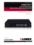
LOREX Video Module
User Manual
Version 1.0
Lorex Module User Manual
-1-
Table of Contents
1. Introduction ......................................................................................................................................... 3
1.1 Features ....................................................................................................................................... 3
1.2 The Lorex module as a Web-based Remote Surveillance System .............................................. 4
1.3 Package Contents ........................................................................................................................ 4
2. Install Lorex module, USB Camera and Network ............................................................................... 6
2.1 Installation Procedure................................................................................................................... 6
3. Installation and Configuration ............................................................................................................. 8
3.1 Installing the Lorex Utility ............................................................................................................. 8
3.2 Using the Lorex Utility .................................................................................................................. 9
3.3 Using the Setup Wizard.............................................................................................................. 10
3.4 Launching the Lorex Module Browser........................................................................................ 12
3.5 IP Configuration.......................................................................................................................... 12
3.6 Upgrading the Lorex Module Firmware ...................................................................................... 13
3.7 Installing the Lorex ActiveX control ............................................................................................ 13
3.8 Installing Java............................................................................................................................. 13
4. Lorex Web-based Viewer.................................................................................................................. 14
4.1 Viewing Live Images .................................................................................................................. 14
4.2 Module Information..................................................................................................................... 15
4.3 Basic Settings............................................................................................................................. 16
4.4 Advanced Settings ..................................................................................................................... 18
Lorex Module User Manual
-2-
1. Introduction
1.1 Features
The Lorex Video module is a compact stand-alone web-server capable of remote video surveillance. It
can be accessed from anywhere in the world via a standard browser by entering the IP, account and
password. Each system can simultaneously support any two combinations of USB PC cameras
(regular, infrared or pan-tilt).
With its built-in web-server, the Lorex module can stream video images directly to the Internet without
have to go through a computer. The Lorex module software allows the computer user to monitor
multiple cameras on one screen and to archive streaming video directly to the hard-drive.
Features:
• Built-in Web Server
• 10/100Mbps Fast Ethernet Network Access
• LCD display shows the IP address, Subnet Mask and Gateway
• 32-Bit RISC CPU
• 1MB Flash Memory
• 8MB Dynamic Memory
• Support Up to 30 Remote Viewers for each camera
• Allow Up to 8 User Accounts and Passwords
• 5.3VDC 1A Maximum
• Operating Temperature: 0°C ~ 60°C
• Operating Humidity: 10% ~ 90%
• Dimensions: 48mm x 63mm x 21m
• Weight: 75g
• For Indoor Use. Protective housing required for use
• Network Protocols: HTTP, TCP/IP, UDP, SMTP, Dynamic DNS, DNS Client, SNTP, BOOTP,
DHCP, FTP, SNMP
• Supports all USB PC Cameras with VIMICRO ZC0301 Plus processor
• Resolution: 640 x 480, 320 x 240, 160 x 120.
• Frame Rate: Up to 20fps in 320 x 240
• MJPEG Compression
• 2 USB Ports for PC Cameras
• USB 1.1 & 2.0 compliant
• Can be used with two different PC cameras
• Supports Pan/Tilt and Infrared USB PC Cameras
Lorex Module User Manual
-3-
1.2 The Lorex module as a Web-based Remote Surveillance System
Once the Lorex module is installed, the user can check any of the connected PC cameras using a
standard web browser. The user can monitor and control these cameras by entering the IP address of
the Lorex module (as set up with Lorex Utility) from anywhere in the world as long as there is an
Internet connection available.
The Lorex module Network Diagram
1.3 Package Contents
Your Lorex module package should contain the following items;
1. Lorex module,
2. Lorex USB camera,
3. Lorex module CD, which contains;
• Lorex Utility: to configure IP address, update the firmware, etc.
•
Lorex Player: Windows video monitoring and recording application.
•
Adobe Acrobat 5.0 Reader.
• Lorex user manuals, and
• Web-support components
4. 5.3V DC Adapter
5. CAT5 Network cable
Lorex Module User Manual
-4-
The Lorex module Front View
The Lorex module Back View
LED Status Indicators on the Lorex module
Light color
Signal definition
Condition description
Green
Power state
On: Normal power
Red
Error Condition
On: Error condition occurred
On: When a user is logged in and
Orange
Logon state
receiving image data.
Flashing: Receiving data via
Yellow
USB data activity
USB.
Light indicators on the Lorex module LAN Port LED
Light color
Condition description
On: Internet speed is 100Mbits/s
Green
Flashing: Data transmitting/receiving
On: Internet speed is 10Mbits/s
Yellow
Flashing: Data transmitting/receiving
Lorex Module User Manual
-5-
2. Install Lorex module, USB Camera and Network
The following details the installation procedure for the Lorex module.
2.1 Installation Procedure
Step 1:
Plug the PC camera into
the USB port of the
Lorex module.
Step 2:
Connect the Lorex
module to LAN by using
the Ethernet network
port.
Step 3:
Plug the DC power
adapter output into the
Lorex module socket,
and plug the DC power
supply into the wall
socket
Lorex Module User Manual
-6-
Step 4:
The LCD will display the IP,
Subnet Mask and Gateway IP.
The icon on the LCD shows
that a USB camera is
connected.
The LCD display shows that
two USB cameras are
attached to the Lorex
module.
Lorex Module User Manual
-7-
3. Installation and Configuration
3.1 Installing the Lorex Utility
Insert the Lorex CD into the CD-ROM drive. The Lorex setup will run automatically. The following
menu will be displayed.
¾ Lorex Utility - This is a program that helps the user configure the hardware. It will detect
the current configuration and take the user through the necessary network setup.
¾ Lorex Player - This is a Windows based program designed to allow the user to view and
record video from multiple Lorex modules.
¾ User Manuals - Click to read the Lorex User Manuals. You will need to have Adobe
Acrobat Reader v5.0 or higher installed.
¾ Acrobat Reader - This will install Adobe Acrobat Reader v5.0 on your local hard drive.
¾ Other - Install Java (J2SE 1.4) and Lorex ActiveX components for viewing video from a
Web browser.
Click on Lorex Utility button and follow the on-screen instructions to install the utility program.
Lorex Module User Manual
-8-
3.2 Using the Lorex Utility
When you start up the Lorex Utility, it will search and list all available network cards on your system. If
more than one is installed, select the network adaptor that you are currently using and click “OK”.
The Lorex Utility Network Adaptor Selection on Start-up
The Lorex Utility main menu is shown below. The selection menu is located on the left. The Serial
Number, current Firmware and IP Address of every Lorex module connected to the LAN will be
displayed on the table to the right.
The Lorex Utility Main Menu
Lorex Module User Manual
-9-
3.3 Using the Setup Wizard
Use “Setup Wizard” to take you through the basic configuration necessary to start using the Lorex
module.
Click to highlight the Lorex module on the right that you want to configure.
Click on “Setup Wizard”.
The Setup Wizard will launch to take you through the configuration below;
Camera Setup
Choose the appropriate frequency (Indoor 60 Hz,
Indoor 50 Hz or Outdoor) to prevent flickering on
the video feed.
Enter a name for the camera in the “Location” box
to identify it.
Click on “Next >”
Network Setup
Choose “Obtain an IP address by DHCP” if
a) you are not sure what the network
address should be and
b) your network supports DHCP
otherwise choose “Use the following IP Address”
and enter an appropriate internal IP Address,
Subnet Mask and Gateway for the Lorex module.
Click on “Next >”
Lorex Module User Manual
- 10 -
Dynamic DNS Setup
You will need to set up this feature only if you are
using a Dynamic IP address (go to
http://ddns.stratgicvista.net for details).
Click on “Next >”
Administrator Account Setup
An administrator account is necessary to ensure
privacy. If you do not set one, the Lorex module
can be viewed by anyone on the web.
NOTE: Make a note of the administrator name
and password and save it in a safe place.
Click on “Next >”
Upload and Save Changes
Click on “Next >” to save and restart the Lorex
module with the new configuration.
Lorex Module User Manual
- 11 -
3.4 Launching the Lorex Module Browser
Once you have finished with the above Setup Wizard, either click “Launch Viewer” or double click on
the Lorex module item in the list to launch the web browser.
3.5 IP Configuration
This section allows you to change the IP address of the Lorex module.
Select the Lorex module on the right display screen, and then click “IP Configuration”. This will bring
up the IP Address Configuration window. There are two tabs;
• IP Address
• Advanced (for port setting configuration)
IP Address
Use this section to set the IP Address of the Lorex module.
Once the IP Address is set, you will be able to connect to the Lorex module by entering this IP
Address into a browser.
Advanced
This section sets a security password for access to devices through the Lorex Utility.
Device Password: Use this to set an access password. Once set, the user must enter the password to
access the device. In addition, the IP Address will not be shown on the right display panel of the Lorex
Utility.
The Lorex Utility will request the “Input Device Password” when you click either “Setup Wizard”,
“Launch the Lorex module” or “IP Configuration”
WARNING: Do not lose this password. If the password is lost, you cannot access the device to make
changes.
To remove the password, you must first enter a valid “Input Device Password”, go to “Device
Password” and delete the entries, click “OK”.
Management Protocol: The administrator can determine the port setting when providing access via
HTTP (web) to the Lorex module. The default port number is 80. Uncheck to disable this function.
Lorex Module User Manual
- 12 -
3.6 Upgrading the Lorex Module Firmware
The Lorex Utility offers a convenient method to upgrade the Lorex module firmware.
1. Click “Upgrade Firmware” to bring up the Wizard.
If you have downloaded the latest firmware to your local hard drive, check “Upgrade the Lorex
module firmware with file saved on the local hard drive” and browse to the file location.
2. Click on “Next >” to check for the latest available firmware.
3. Select new firmware file (*.bin)
4. Click on “Start”.
The Lorex module red and yellow LED will flash alternately to indicate that firmware upgrading is in
progress. Once completed, the Lorex module will reboot.
NOTE:
If the downloading / upgrade process is interrupted or the data is corrupted, the Lorex module will
keep its default firmware to avoid complete data loss. If this happens, repeat the above firmware
upgrade procedure.
Please check http://www.lorexcctv.com/ for the latest firmware.
3.7 Installing the Lorex ActiveX control
The Lorex ActiveX control is required to view video images using Microsoft’s Internet Explorer web
browser.
From the Install CD, click on ‘Other’ and select “Install ActiveX control” from the menu and follow the
on-screen instructions.
3.8 Installing Java
Java is required to view video images from a web browser other than Microsoft’s Internet Explorer.
From the Install CD, click on ‘Other’ and select “Install Java” from the menu and follow the on-screen
instructions.
Lorex Module User Manual
- 13 -
4. Lorex Web-based Viewer
After you have set up the hardware and set an IP address for the Lorex module, you will then be able
to go to the Lorex module web site to monitor and control the PC cameras. All you have to do is enter
the Lorex module’s new IP address into the web browser.
Once you have done the above, the Lorex module login screen will appear. Key in the administrator
account name and password entered earlier (if you did not input one, then just press ENTER or click
on the “OK” button). The Lorex module web page will appear.
4.1 Viewing Live Images
In order to view live images with the Lorex ActiveX control you must use Microsoft’s Internet Explorer
6.0 or higher. You may need to pre-load the control (see Lorex Utility) to allow this to work.
Alternatively, you can use Sun’s Java with your choice of browser, provided this has been installed on
your computer.
Click 'ActiveX' or 'Sun Java' for Camera A or Camera B to view the video images.
Note: The first USB camera connected to the Lorex module will be denote as “Camera A”, and the
second camera connected will be “Camera B”. If there is only one camera, it will always be “Camera
A”.
Make sure to adjust the USB camera lens
for best picture results.
Click on the controls along the Window to
control the camera.
Functions are:
•
•
•
•
•
•
•
•
•
•
Record the current image to the
local hard drive
Digital zoom in, digital zoom out
Rotate left, rotate right
Flip image vertically
Flip image horizontally
Auto-pan
Pan left 5 deg/1 deg
Pan right 1 deg/5 deg
Tilt up 5 deg/1 deg
Tilt down 1 deg/5 deg
Note that the pan and tilt controls will only
work with cameras that have this function
built in.
Lorex Module User Manual
- 14 -
4.2 Module Information
Click on the ‘Information’ link in the left hand navigation pane to expand the list of options. Select one
of the options under ‘Information’
System Status
This provides a summary of the module and
network status.
Take note of the unique MAC address, which is
needed to register for product software,
services and support.
Current Connections
This section will show all the users currently
viewing either Camera A or Camera B. It also
lists the login time and total bytes received.
A total of 10 connections can be displayed at
the same time.
The administrator has an option to block the IP
or disable the account of any viewer.
Event Log
This section will keep a record of all events that
occurred in the Lorex module. The user can
Refresh, Clear or Save the log file. There is also
an option to sort the logs according to “Level” or
“Type”.
The Lorex module can log up to 2,000 events.
Note: Set the internal clock to ensure that the
logs are correctly time-stamped.
Lorex Module User Manual
- 15 -
4.3 Basic Settings
Camera Settings
By default the Camera Settings page is
displayed when you log in.
Anti Flicker: Choose between 50Hz, 60Hz or
Outdoors. Note: If you do not choose the right
frequency, the image will flicker or lines will
appear on the images.
Maximum Number of Connections (1-30): Limit
the number of users that can connect to this
camera.
Location: Enter a location/name for the camera.
Exposure (1-100): Set this to “Auto”, or click
“Manual” to fix the exposure.
Light Compensation: Choose “Yes” and the
Lorex module will increase the lighting of the
image. This is useful when monitoring indoors.
Choose “No” if you do not want the Lorex
module to adjust the light.
Color: Choose “Yes” for color and “No” for black
and white display.
White Balance: Choose “Auto” to let the Lorex
module make auto adjustment. To adjust this
manually, select “Manual” from the drop down
menu, and then enter a suitable number for
Red, Green and Blue.
Click “Apply” to save changes.
Lorex Module User Manual
- 16 -
Network
This option determines the Lorex module
Network settings. Note that there is more than
one way to update network settings.
Obtain an IP address: This allows the user to
choose either to set the Lorex module IP
Address manually or via DHCP. The Lorex
module will reboot after the above settings have
been changed.
Manual address determination requires IP
Address, Subnet Mask, Gateway and DNS
servers to be explicitly set.
Two ports are required for web and video image
access.
By default the HTTP Port Number is 80
By default the Communication to Camera Port
Number is 9001
Ethernet “Connection Type” sets the
communication speed between the Lorex
module and the Network. The Lorex module will
reboot after “Connection Type” is changed.
Dynamic DNS
The Lorex module can be configured to register
the current IP to a Dynamic DNS provider. This
will enable you to locate the Lorex module’s IP
every time the IP changes due to an ADSL
connection redial. Before you use this function,
you will have to register with a service provider.
For more information and to sign up visit
http://ddns.strategicvista.net
Account Settings
This section allows you to set up to eight user
accounts with different permissions for the
Lorex module.
“User Name”
Determine the user names of visitors who can
log in. The administrator can set up to 32 casesensitive names.
“Password”
Set a password for each visitor’s account.
“Permission”
Determine the permission level to one of
“Administrator”, “Operator”, “Viewer” or “No
Access”
Lorex Module User Manual
- 17 -
4.4 Advanced Settings
Event Notification
The Lorex module can send email notifications
in response to certain events.
Note: You must have Administrator privilege to
edit this section.
To activate Event Notification, set “Send Email”
to “Yes”. Select “No” if you do not wish to send
out any notifications.
A valid “Email Server” with username and
password (if authentication is required) must be
available for this feature to work. To change the
settings, click on “Edit”.
There must be at least one valid email address
in the address book. To add or delete entries,
click “Edit”.
The Lorex module can send to up to 8 valid
email accounts. To add an email to the recipient
list click on “<” to remove click on “>”.
Click on “Events” to select from the list of
events to be notified. There are three types of
events, Information, Warning and Error.
By default, all the events are selected; Click
“Apply” to activate them. Close the window to
return to the Event Notification Page. Click
“Apply” to save your settings.
Note: The image recording and motion
detection notification function here will send an
email notification WITHOUT any pictures
attached. For email notification with images, the
set up the Image Recording and Motion
Detection under Advanced Settings.
Lorex Module User Manual
- 18 -
Motion Detection
To activate motion detect, the administrator has
two options;
•
“Always On” or
•
“On Schedule” (up to 4 time slots)
“Detection Sensitivity” will determines level of
change before motion capture is triggered.
“Send image every” : Select a value between 1
to 5 seconds.
“Stop sending emails after ## email(s) or image
idle for ## second(s)” : The Lorex module will
stop sending on the lower of the two conditions.
You can set seconds as 1, 3, 5, 7 or 10. Emails
can be set from 1 to 99999 messages, or 0 to
stop sending emails only when image idle
occurs.
“Schedule” : If “On Schedule” is set (see above), then define the four preferred schedule time slots for
motion detection. Time must be entered in 24hr format.
“Send to FTP Server” enables sending motion- detected images to an FTP site. Click “Yes” to activate.
The ftp:// field determines the file location within the FTP site. If you have not entered a FTP server,
the above will be <Empty>
To setup the FTP server, click “Edit” to go to the Email / FTP Page. Once you have entered the FTP
server, login name and password, click “Apply” and then Click on “Motion Detect” to return here.
Enter a directory or folder name in the edit field following the ftp:// site. Click “Apply” when done.
“System Defined / User Defined” determines filenames for the images.
“Filename” gives the motion detected JPG images a standard filename prefix, to be followed by
looping number suffix.
“Loop from ## to ##” determines the number of suffixes preceding the above filename. Once the last
number is reached, the first file will be replaced by the most current image.
“Digits”
This will determine the number of digits assignable for the above number suffix. The administrator can
choose to assign between 1 and 6 digits.
Set “Send Email” to “Yes” to send email notifications of Motion Detection with images.
“Email Server”
If not set up click “Edit” to go to the Email / FTP Page. Click on “Motion Detection” to return.
“Recipient” & “Email Address Book” determines who shall receive email notification. To add to the
recipient list, either double click on the email in the address book or click “<”. To add all the email
address at once, click “<<”. To remove an entry click “>”, or “>>” to remove all entries from the
recipient list.
Click “Apply” to confirm and save the settings.
Lorex Module User Manual
- 19 -
Image Recording
Image recording causes the module to send an
image to either an email account or to an FTP
server. The images will be sent at
predetermined intervals over a period of time.
For Camera A (or Camera B)
Begin – End (hh:mm):
Set up to 2 time slots when Image Recording is
active. The time is in 24hr format.
“Send image every ## minute(s)”
Set the interval at which the Lorex module
captures and sends an image. ( 1, 3, 5, 7 and
10 mins.)
Send to FTP Server & Send Email:
Refer to the Motion Detection Page.
Email/FTP
This section sets up the necessary Email and
FTP server information to allow email
notification and ftp file sending features. The
administrator must enter a valid Account Name
and Password for the Email server and/or FTP
server.
FTP Settings
Enter the FTP server address, account name
and the corresponding password. Click “Apply”
to save the settings.
Email Settings
Enter the Email server address and Lorex
module’s Email address.
If “Email Server Requires Authentication” is set
to “YES”, provide the account name and
password in order to access the Email server.
Click “Apply” to save the settings.
Email Address Book
Enter an Email address in the box provided and
click “Add Email Address”. The new email
address will be added to the list. The module
can store up to 20 email addresses.
Lorex Module User Manual
- 20 -
System Settings
System Time
The administrator can set an interval for
Automatic Time Synchronization. Select either
1, 3, 12 hours or 1, 10 & 30 days. Choose the
nearest Time Server to your location from the
list of 30 Time Servers. (Add a new Timer
Server by deleting deleting an existing entry).
Select the appropriate time zone for your area
and click “Apply” to save.
Manually set the Lorex module System Time by
entering the time in the format: yyyy/mm/dd
hh:mm:ss and click “Manual Adjust”.
System Restart
If necessary, restart the Lorex module manually by clicking “Restart Now” or at regular intervals.
Choose between minutes and hours only and click “Apply”.
LED Settings
The administrator can enable or disable the LED (except the Power LED) on the Lorex module here.
Click “Apply” to save the setting.
SNMP Settings
Set the Lorex module SNMP settings so it can be used by an NMS (Network Management System).
System Name: Lorex module name identifiable in an SNMP network.
System Contact: administrator’s name.
System Location: Lorex module location.
Manager IP Address: IP address from where the administrator can manage the Lorex module. It is
valid for up to 8 IP addresses. To manage the Lorex module from any IP addresses leave it as *.*.*.*.
Community: The community name has to be the same as that set in the NMS.
Permission: Options are Read, Read/Write, and No Access.
Description: For administrator’s notes.
Lorex Module User Manual
- 21 -
About
This screen provides module version
information.
Use “Save” and “Restore” to respectively save
and restore module settings to a file on your
computer. The text file will have a default name
format of YYYY_MMDD_xxxx.cfg.
Use “Reset” to overwrite all settings with the
factory defaults. (Use with caution, as all
settings will be lost).
Click “Upgrade Firmware” to check for the latest
firmware. The Lorex module will automatically
download and install the latest firmware
Lorex Module User Manual
- 22 -