1
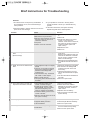
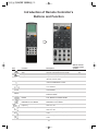
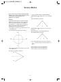
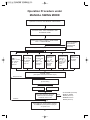
SMARTPONG
SMARTest ping PONG robot in the world
USER'S MANUAL
Warranty
We provides a full one year warranty on any manufacturing defects with our
robots. Any returned robots found to be abused,mishandled, modified, or
altered will void the warranty.
During the first 90 days, we will cover costs required to fix the problem. All
products, after the warranty period, may be repaired with a reasonable
service charge, provided that the product is repairable with the owner
covering the initial shipping cost.
We guarantees to always have a 3 year supply of spare parts available to
our customers.
Important!
If you want to use your own 40 mm table tennis balls, please make sure that
your balls easily pass through the hole shown in the picture. If they don’t
pass through easily, they may get stuck, and cause the robot to not work
smoothly.
2
Table of Contents
Functions and Features ............................................................... 4
Important Safeguards and Cautions for Installation ................ 5
Contents and Specifications ........................................................ 6
Table Tennis Robot Assembly and Disassembly .......................... 7
Brief Instructions for Troubleshooting ............................................. 9
Remote Controller’s Panel and LCD Display
Introduction of Remote Controller's Buttons and Function ............10
Service Modes ...............................................................................12
1. AUTO MODE ..............................................................................13
2. MANUAL FIXED MODE and MANUAL SWING MODE..........14
3. MEMORY/CYCLE MODE ..........................................................16
LCD Display, Button’s Function and Operation
under Each Mode
1.AUTO MODE ..............................................................................17
2.MANUAL FIXED MODE ..............................................................19
3.MANUAL SWING MODE ............................................................22
4.MEMORY/CYCLE MODE ...........................................................24
Operation Procedure under Each Mode
1.AUTO MODE ..............................................................................28
2.MANUAL FIXED MODE ..............................................................29
3.MANUAL SWING MODE ............................................................30
4.MEMORY/CYCLE MODE .................................................................31
3
Functions and Features
Automatic Table Tennis Robots
Functions and Features
•The robot is equipped with the state-of-the-art
microcomputer to provide stable performance and
powerful function.
• Infrared remote controller with LCD display,
comprehensive user’s manual and vcd demo
program to facilitate user’s
installation and operation.
• Automatic ball collector
• AUTO MODE: 9 default service modes with
different difficulties. The operation is easy and it is
suitable for general exercise and entertainment.
• MANUAL FIXED MODE: Allowing players to
manually coordinate 3 axes (spinning, elevation
and swinging from left to right), parameters
(service frequency, speed and run time) and single
or multiple services at a fixed point
• MANUAL SWING MODE: The operation is similar
to the above, but this mode allows players to
configure the range of swinging from the left to the
right, so players may have single or multiple
services of balls in swing mode.
• MEMORY/CYCLE MODE: With the function of
memory saving/clearing under MANUAL FIXED
MODE, players are allowed to arrange their own
service mode. This increases the challenge and
fun, and also satisfies the demand of professional
players.
• This is the only automatic table tennis robot with
infrared remote controller and has patents granted
in the USA, Japan, Germany and other countries.
Patent
Patent
Patent
Patent
Patent
No.: USA 6,186,132
No.: Japan 3063534
No.: Germany 29907698.9
No.: China 378739
No.: Taiwan 159508
4
Important Safeguards and Cautions for Installation
Thank you for purchasing this table tennis robot (For
convenience, We use ”robot” or ”device” intead of
”table tennis robot” subsequently). Before using it,
you should read this user’s manual carefully and
keep it for future reference. Please be sure to follow
the following safety guidelines.
Cautions for Installation
Make sure this device is installed in a well
ventilated place of good ventilation and is kept away
from high temperatures or humidity.
Please do not install this device near direct sunlight
or a heater. Excessive heat may damage the shell
of this device and its internal components.
Malfunction might be caused if this device is
installed in a humid dusty place, or smoky
atmosphere
Important Safeguards
1.Do not insert your fingers into this device.
2.Do not allow any object or liquid to come into
contact with this device through its vent.
Should the following situations occur, please contact
the dealer.
3.AC power.
– When unplugging the AC power cord, pull the plug
itself and not the power cord.
– AC power cord or plug is damaged.
– Never touch the AC power plug with wet hands.
– This device has been exposed to rain or high
humidity. abnormal operation occurs.
– Other objects or liquid enters this device.
– The power cord should be free from bending or
twisted
– There is significant change in the performance of
this device.
– When plugged into an outlet, do not overload or
use an extended AC power cord to avoid fire or
electric shock.
– This device has been dropped or the shell is
damaged.
Never try to disassemble or repair this device by
yourself.
4.Important, table tennis balls meeting with the
international standard (40 mm) are accepted for
this device – Nonconforming table tennis balls
may cause malfunction or damage to the robot.
5
Contents and Specifications
Contents:
Specifications
1. Side Nets ............................................................. 2
Power: AC 88V~240V
Service per minute: (Slowest) 30~(Fastest) 90 balls
Angle of elevation: 1~28 (Around 50°)
Range of swinging: 1~9 (Around 60°)
Spinning: 360°
Weight: 9 kgs
Power Consumption: (220V) 1.2A~(110V) 2.3A
Battery for the Remote Controller: AAA x 3
2. Brackets ............................................................... 2
3. Pads (No. 1, No. 3/4, No. 1/2) ............................. 1
4. Remote Controller ............................................... 1
5. Remote Controller’s Pouch + Velcro ................... 1
6. Battery (AAA x 3) ................................................. 1
When the remote controller’s buttons are left
untouched for 30 seconds, the power saving
function will turn off the display. Once a button is
touched, the display will resume to the default
settings
7. AC Power Cord .................................................... 1
8. 40mm Ping Pong Balls (100 pcs) ......................... 1
9. USER’S MANUAL ................................................ 1
Please note:
• If any of the contents is missing or there is any
damage to the robot, contact the dealer.
• All specifications are subject to change without
prior notice.
• If necessary, retain the external packing carton.
• There may be some variation between the
illustrations and the actual products.
6
Table Tennis Robot Assembly and Disassembly
(1) Left/Right Pipe
(2) Transparent Cap
(3) Ball Separator
(4) Base (Undercarriage or ball service tray)
(5) Right Pipe
(6) Left Pipe
(7) Left/Right Ball collecting tray (ball track)
(8) Server Head
(9) Infrared Sensor
(10) Middle Pipe
(A) The system (robot server)
Assembly
5.Based on the thickness of the table, attach the
appropriate pads to the left and the right pipes in
the front. When the table thickness is 25mm use
the No. 1 pad, when the table thickness is 21mm
use the No. 3/4 pad, when the table thickness is
17mm use the No. 1/2 pad.
To optimize the performance of this
robot, make sure to follow the
assembly instructions as below:
The assembly of this robot is very
easy. No special tools are required. If
you follow the following steps you can
complete the assembly within 5
minutes.
6.Load motor on the center trough of Base put 2
screws on the hole, then fasten them.
1.When you take the robot from the
packing carton, please hold the iron
pipe with one hand and the base
with the other. The back of the robot
server should be face towards the
user and be placed on the table.
7.Place your both hands at the sides of the base to
lift the whole system and insert the front tubes
under the table at 45° while aiming the tip of the
triangle clamp to the middle line of the table.
2.Withdraw the pipes from both sides
of the base and insert them into the
straight iron tube.
9.The system is now ready to operate with the
control of the remote controller (See P10-P11).
3.Lift the left and the right ball
collecting tray then put them down
carefully.
Please Note:
8.Plug one end of the power cord to the robot AC
power input and the other to the AC outlet.
If a ball or any object becomes obstruct somewhere,
the buzzer will beep for 2 to 3 minutes then the
system will start repositioning. Please turn off the
power until the problem is solved.
4.Pull out the triangle bracket in front
of the robot (supporting bracket at
the bottom), then open the left and
the right pipes.
7
Disassembly
Cleaning and Maintenance
It takes only 2 minutes to disassemble this system.
How to Clean the Shell
1.Unplug the AC power cord.
A soft piece of cloth is sufficient for moderate
soiling. If the system becomes dirty, please prepare
a 1:6 solution of soap and water and clean with a
soft piece of cloth, then dry with another dry cloth.
Never use strong solvents, such as alcohol, benzene
or other volatile cleansers.
2.Place your hands beside the base, lift the whole
system slightly and pull it back. Then you may
place the whole system on the table.
3.Gather the balls from the left and right ball
collecting trays in the base, then place the ball
separators from the sides to stop the balls from
falling.
To avoid accidents, always unplug the power cord
of the system while cleaning this device.
4.Draw in the left and right pipes and gather them in
the base.
How to Maintain the System
5.Return the ball collecting trays upwards to their
original positions (both sides).
Please wash the table tennis balls regularly to
remove dusts and hairs because these can cause a
malfunction of the system.
6.Draw out the pipes of both sides from the iron
tubes and insert them to the holes at the left and
right sides of the supporting bracket.
If the balls are distorted, squished or wrongly size,
stop using them to prevent further damage to system.
A switching power supply is built into the system, to
accommodate all international voltages (AC 88V~
240V).
• After plugging, the robot server head will rotate to
its ready position. When the remote controller is
turned off (while aiming at the infrared sensor at
the system), the system will also return to its
original position.
• Please unplug the AC power cord if the system is
not to be in use for a period of time.
• If the left or the right ball collecting tray is taller
than the tabletop, the balls will not fall on the table,
so the pads should be changed to decrease the
angle of elevation.
• Before putting the balls into the machine, please
make sure their sizes are standard to avoid
possible breakdown of the system. Never use balls
other than 40 mm.
8
Brief Instructions for Troubleshooting
Remarks:
1.This device does not require any modification. If
any breakdown occurs, check the following to
solve problems.
3.If your problem is not found in the list, please
contact the dealer. Never try to reassemble it by
yourself.
2.Until the problem is solved, make sure to turn the
power off to avoid damage.
4.If the ball is obstructed, the system will keep
repositioning itself to the default position.
Problem
Cause
1.Power is not turned on.
2.Ball Service tray is blocked.
3.Remote control distance is too far
from the system or there is an
obstacle in between.
4.No power.
5.Failure of remote controller.
Solution
1.Check if the power cord is plugged
in.
2.Refer to B.
3.Shorten the distance of remote
control or move away the
obstacle. If this does not work out,
the system or remote controller
could have failed. (Send it to
repair center)
4.Replace the fuse.
5.Refer to D.
1.Blocked with balls or other objects
1.blocked with balls – turn off the
power first!
Remove the transparent cap and
measure the diameter of the ball.
Do not use any oversized or flat
balls to avoid blockage.
2.Blocked with unspecified objects
or conflicted with the ball service
gear.
C. Weak, abnormal or failed service
balls
1.The transparent cap is not tightly
sealed
2.There is not any ball on the ball
service tray because the ball is
blocked in the left/right ball
collecting tray.
3.The ball service tray is blocked
with a ball or other objects.
4.Ball too small (38 mm)
5.The spring of the ball service tube
is broken.
1.Reseal the transparent cap tightly
2.Put the ball in the left/right ball
collecting tray back to the ball
service tray.
3.Check the ball service tray and
remove the blocked ball or object,
if any.
4.Use the international standard 40
mm balls.
5.Send it to repair center
D. The system works, but does not
respond to the remote controller
1.The conductive plastic of the
remote controller is aging.
2.Invalid service modes. under
AUTO MODE, only the runtime,
ball service frequency and
memory modules are available.
3.Insufficient battery power for the
remote controller.
4.Remote controller does not aim at
the system correctly.
1.Send it to repair center.
2.Please refer to the USER’S
MANUAL of the remote controller.
If problem still exists, send it to
repair center.
3.Replace with new battery.
4.Aim the remote controller at the
system directly.
E. No display on LCD
1.Insufficient battery power.
2.Opposite battery direction.
3.LCD breakdown.
1.Replace with new battery.
2.Check the pole direction of battery.
3.Send it to repair center.
F. Memory function does not work
1.Incorrect memory settings.
2.PCB failure.
1.Please refer to the USER’S MANUAL
P19~21 to restart memory setting.
2.Send it to the repair center.
A. System fails to start.
Remote controller
System
B. Ball service tray is blocked with
balls.
(Buzzer beeps)
9
Introduction of Remote Controller’s
Buttons and Function
Icon
START
STOP
AUTO
MANU
Aim the remote
controller at the
system?
Function
Description
Power
Remote controller power switch
No
Start
Start the (continual) service of balls
Yes
Single service
Single service (only one ball)
Yes
Stop/End
Stop the service of balls
/End the current mode
Yes
Increase/Decrease module number
Select (Designate) the modules 1 to 9
under AUTO/MANUAL modes
No
Increase/Decrease the runtime
Set the runtime of current mode from 01
to 15 minutes
No
AUTO MODE
Start the LCD display under
AUTO MODE
No
MANUAL MODE
Start the LCD display under
MANUAL MODE
No
Switch between FIXP/SWING
MODE
Switch between the LCD displays under
FIXP MODE and SWING MODE
No
Set the LCD display to
MEMORY/CYCLE MODE
No
MEMORY/CYCLE MODE
Increase/Decrease the service
frequency
Set the service frequency (BALL FREQ)
from 01 to 40
No
Increase/Decrease speed of service
Set the speed of service (BALL SPEED)
from 01 to 99
No
Increase/Decrease Ball spin
Set the spinning of balls (CIRA) from 01
to 59
Yes
Increase/Decrease of elevation
Set the angle of elevation (UDA) from 01
to 28
Yes
10
Icon
Function
Description
Increase/Decrease left/right limits
under FIXED/SWING MODE
• Under FIXED MODE, it is used to set
the fixed left/right position (LRA) from
1 to 9.
Aim the remote
controller at the
system?
Yes
• Under SWING MODE, it is used to set
the left limit (LFLIM) and the right limit
(RTLIM).
- is for the left limit from1 to 9
+ is for the right limit from 1 to 9
* Remark: LFLIM<RTLIM.
M
Memory set/save
Under FIXED MODE, aim the remote
controller at the system and press
F2+M for 3 seconds until the system
beeps. The system then saves the
current settings to the designated
memory modules (1 to 9).
Yes
* Remark:
1: F2+M for memory saving is only valid
under MANUAL FIXED MODE.
2: Memory always remains even after
the power is turned off.
CLR
Memory clear
Under FIXED MODE, aim the remote
controller at the system and press
F2+CLR for 3 seconds until the system
beeps. The system then clears the
current parameters from the designated
memory modules (1 to 9)
* Remark: F2+CLR for memory clearing
is only valid under MANUAL FIXED
MODE.
11
Yes
Service Modes
There are four service modes provided by this
system: AUTO MODE, MANUAL MODE (Including
FIXED MODE and SWING MODE) and
MEMORY/CYCLE MODE.
3.(
) has FIXED MODE and SWING MODE.
FIXED MODE (
is 5.
5
) ranges from 1 to 9. The default
The FIXED MODE is as below:
Remarks:
In MANUAL FIXED MODE or MANUAL SWING
MODE, the angle of elevation, left or right limits,
service speed and frequency are available for
reconfiguration. If a player does not modify the
settings, the default setting will be elevation 15,
left/right limits 5 and service speed 15.
1.The degree of spinning (
The default is 01.
1
) ranges from 01 to 59.
5
9
SWING MODE (
) ranges from 1 to 9 from the
46
left to right.
The coordinate axis of spinning is as below:
The left default is 4 and the right default is 6.
01
The SWING MODE is as below:
46
16
1
4
6
9
4.The relationship between the service frequency
(
) and the number of balls per minute is as
below:
31
2.The angle of elevation (
The default is 15.
Service frequency at 01: 30 balls/minute
Service frequency at 20: 60 balls/minute
Service frequency at 40: 90 balls/minute
) ranges from 01 to 28.
The angle of elevation is as below:
28
15
01
12
AUTO MODE
AUTO MODE has 9 default service modes with
different difficulties. A player may select his own
service mode to practice according to his skill and
requirements.
Remarks:
Under AUTO MODE, the coordinate axes or
parameters not shown on LCD are default settings,
so no setting is required. AUTO MODE is thus the
easiest one to use during the 4 modes available.
Under AUTO MODE, a player is only required to
select a ball route memory module (1 to 9), service
frequency (01 to 40) and runtime (01 to 15 minutes),
then aim the remote controller at the system and
press START. The system then responds to your
demand and starts servicing balls for your practice.
The service of balls will not stop until the designated
runtime is out or the player presses STOP.
There are two ways to start AUTO MODE:
1.Press (power on-off) button to turn on the
remote controller
(LCD displays a self-test program and start AUTO
MODE.
2.Under other modes, aim the remote controller at
the system, then press STOP to stop the current
mode.
Press AUTO to enter AUTO MODE and the LCD
display is shown as below:
Button Indicator
On: Button is available
Battery/Power
On: Sufficient power
Off: Button is not available
Blinking: Power is insufficient,
please replace with new
batteries.
Runtime
(01 to 15 minutes)
AUTO MODE
Ball Route Memory
Module (1 to 9)
Service Frequency
(01 to 40)
13
MANUAL FIXED MODE and
MANUAL SWING MODE
MANUAL MODE includes FIXED MODE and
SWING MODE. Both mode allow users to configure
each coordinate axis (such as spinning, elevation
and left/right limits) and parameters (such as the
frequency of service, speed and runtime) based on
their specific requirements (for professional players).
After the manual settings of each coordinate axis
and parameters, MANUAL MODE allows users to
Remark:
Under FIXED MODE, when users execute the
function of memory setting, the system will
automatically record the current coordinate axes
and settings in the memory modules from 1 to 9.
3 Pressing
ball single shot button leads to
different single-ball services:
press
ball single shot button to demand the
system to serve one ball only to check if the settings
meet with user’s demand.
(a) Under FIXED MODE, the service of single ball is
practiced at a fixed direction within the range
from the left to the right (LRA).
Users may then press START to ask the system to
start the continual service of balls until the runtime is
over or STOP is pressed.
(b) Under SWING MODE, the service of single ball
is practiced at alternating directions. After the
service of a ball within the left limit (LFLIM), the
system then switches to the right limit (RTLIM)
automatically and vice versa.
The above operations are similar for both MANUAL
FIXED MODE and MANUAL SWING MODE, but
there are four major differences:
4 Pressing START leads to different practices of
continual supply of balls:
1 Left/Right positions:
(a) FIXED MODE defines 9 fixed positions (LRA from 1
to 9) of service within the range from left to right.
During the service of balls, the direction is always
fixed.
(a) Under FIXED MODE, the direction of continual
service of balls is fixed within both sides (LRA)
and the service of balls does not stop until the
runtime is over or users press STOP.
(b) SWING MODE defines the left limit (LFLIM) from
1 to 9 and the right limit (RTLIM) from 1 to 9.
During the service of balls, the direction is
constantly alternating.
(b) Under SWING MODE, the direction of continual
service of balls alternates within the range from
the left limit (LFLIM) to the right limit (RTLIM)
and the service of balls does not stop until the
runtime is over or users press STOP.
Remark:
The left limit should be smaller than the right one.
Remark:
1.MANUAL FIXED MODE allows users to practice
with single or continual service at a fixed
direction. Besides, it also provides memory
saving/clearing function to preset the
MEMORY/CYCLE MODE to control the settings of
memory module from 1 to 9. Namely, users may
arrange their own service patterns (ball routes)
based on their ability and demand.
2 Memory saving/clearing function of module 1 to 9:
(a) FIXED MODE allows users to save the settings
of designated memory modules (1 to 9) by
pressing F2 and M buttons for 3 seconds until
the system beeps. It also allows users to clear
the settings by pressing F2 and CLR for 3
seconds until the system beeps.
2.MANUAL SWING MODE allows the service of a
single ball or multiple balls within the range of two
positions.
Remark:
The memory saving and clearing function under
FIXED MODE is mainly for users to arrange his own
settings under MEMOR/CYCLE MODE. So the
user may request the supply of balls based on his
demand. This unique feature is one of the
advantages other companies in the world fail to
achieve.
(b) SWING MODE does not provide the function of
memory saving and clearing.
14
LCD Display under MANUAL FIXED and
MANUAL SWING MODE
(a) LCD Display under MANUAL FIXED MODE
Runtime (01 to 15 minutes)
Memory
module
(1 to 9)
Fixed left/right
position under
Fixd mode
(1 to 9)
Service
frequency
(01 to 40)
Elevation
(01 to 28)
Spinning
(01 to 59)
Speed
(01 to 99)
(b) LCD Display under MANUAL SWING MODE
Runtime (01 to 15 minutes)
Memory
modules are
not available in
SWING mode
Left limit
(1 to 9)
Right limit
(1 to 9)
Service
frequency
(01 to 40)
Elevation
(01 to 28)
Spinning
(01 to 59)
15
Speed
(01 to 99)
MEMORY/CYCLE MODE
In any mode, aim the remote controller at the
(b) LCD Display under MEMORY/CYCLE MODE
with modified settings (the memory module is 2
and the setting is modified (not empty)).
system and press STOP and
memory/cycle
button to start the MEMORY/CYCLE MODE. In this
mode, system will automatically combine the
memory modules from 1 to 9 which are configured
by MEMORY SET/SAVE (press F2 and M) and
MEMORY CLEAR (press F2 and CLR) under
Memory
module
(1 to 9)
MANUAL FIXED MODE. When users press
ball single shot button, system will start serve one
ball only or continual service of balls when START is
pressed until the runtime is over or STOP is
pressed.
*Left/right
limit
(1 to 9)
*Service
frequency
(01 to 40)
From the above explanation, we know that we may
program the service mode with the memory saving
and clearing functions for the memory module 1 to 9
in MANUAL FIXED MODE, then start the
MEMORY/CYCLE MODE to start single or continual
service of balls.
*Elevation
(01 to 28)
*Spinning
(01 to 59)
*Speed
(01 to 99)
Remarks:
Under MEMORY/CYCLE MODE, the LCD of the
remote controller will have different displays
according to the existing memory module (1 to 9)
and whether or not the memory is set or cleared
(empty). The following assumes that the memory
module is 1, but the LCD display could vary based
on the settings or clearing of the memory:
Remarks:
The * stands for the value of the designated
memory module (The content can be controlled by
MEMORY SET or MEMORY CLEAR under
MANUAL FIXED MODE. These configurable values
with * include spinning, elevation angle, left/right
range, control settings,: service frequency and
speed).
(a) LCD Display under MEMCYL MODE without any
setting (The memory module is 1 and the setting
is not done (empty).
16
LCD Display, button’s function and operation
under AUTO MODE
• LCD Display under AUTO MODE:
Button
Indicator
On: Available
Off: Unavailable
Runtime:
(01 to 15 minutes)
Battery/Power
Indicator
On: Sufficient power.
Blinking: Power is
out, please prepare
to replace with new
battery.
AUTO MODE
Modules (1 to 9)
Service Frequency
(01 to 40)
• Button function under AUTO MODE:
Icon
Button
Does the remote
controller need to
aim at the system?
Function
Increase/Decrease runtime from 1 to
15 minutes. The default is 1 minute.
Select module numbers under AUTO
MODE from 1 to 9. The default is 1.
AUTO
START
No
No
Increase/decrease service frequency
from 01 to 40. The default is 20.
No
Press AUTO to start the LCD display
under AUTO MODE.
Press START to enable the system to
start the service of balls according to
the designated module number (1 to
9), service frequency and runtime until
time is over or STOP is pressed.
No
Yes
17
The memory modules from
1 to 9 under AUTO MODE
include the default
coordinate settings and
parameters (service
patterns).
01: 30 balls/minute
20: 60 balls/minute
40: 90 balls/minute
Yes
Press STOP to stop the current
operation and reset the 3 coordinate
axes for new command and new job.
STOP
Remarks
To switch to other modes
(such as MANUAL MODE
and MEMORY/CYCLE
MODE) or execute AUTO
MODE, make sure to press
STOP to stop the current
job first.
• Button function under AUTO MODE:
Icon
Button
MANU
Does the remote
controller need to
aim at the system?
Function
Press MANU to start MANUAL MODE.
The LCD will display the settings of
MANUAL FIXED MODE (default).
No
Press this button to start MEMORY/
CYCLE MODE. The LCD will display the
settings of MEMORY/CYCLE MODE.
No
The power button of the remote controller.
Press the first time to turn on, the
second time to turn off.
No
Remarks
Under AUTO MODE, press
STOP before pressing
MANU.Under AUTO MODE,
press STOP before
pressing
button.
To turn off the system
power, unplug the AC power
cord of the system.
Remark:
Aim the remote controller at the system. System beeps when the command is received through infrared
receiver, then the command is executed and the pressed buttons may be released.
Suggestions under AUTO MODE
Suggestion (B)
How to switch from AUTO MODE to MANUAL MODE.
Suggestion (A)
(B1)Aim the remote controller at the system and
press STOP. When the system beeps, release
the button. System now stops its current action
and prepares to receive new commands.
How to practice module 3 under AUTO MODE (1 to 9)
for 2 minutes at service frequency 20 (default).
When the LCD displays AUTO MODE on the remote
controller, do the following:
(A1)Press
(B2)Press MANU to switch to the LCD display
under MANUAL MODE (The default is
MANUAL FIXED MODE).
button to select the module number 3.
(A2)Press
minutes.
buttons to select the runtime as 02
Suggestion (C)
How to switch from AUTO MODE to MEMORY/CYCLE
MODE.
(A3)Press
buttons to select the service
frequency as 20. (This procedure can be
omitted because the default is 20.)
(C1)Aim the remote controller at the system and
press STOP. When the system beeps, release
the button.
(A4)Aim the remote controller at the system and
press START. When the command is received,
the system beeps and starts serving balls.
(C2)Press
button to switch to the LCD display
under MEMORY/CYCLE MODE.
Remarks:
The continual service of balls will not stop until the
2-minute runtime is over. If this operation is to be
stopped in advance, please aim the remote
controller at the system and press STOP. When the
system beeps, the service of balls is stopped and
the three coordinate axes are reset to origin
position.
18
LCD Display, button’s function and operation
under MANUAL FIXED MODE
• LCD Display under MANUAL FIXED MODE
Tips for Setting
For the configuration of a higher range, the remote
controller does not need to aim at the system until
the range of configuration gets smaller. This way
saves time and prolongs the life of the robot.
Runtime (01 to 15 minutes)
Memory
module
(1 to 9)
Fixed
left/right
position
(1 to 9)
For example: When the value of spinning is to be
increased from 01 to 31, the remote controller does
not need to aim at the infrared sensor of the system
until the value approaches 30, then aim the remote
controller at the system and press the + button.
Service
frequency
(01 to 40)
Elevation
(01 to 28)
Spinning
(01 to 59)
Speed
(01 to 99)
• Button function under MANUAL FIXED MODE:
Icon
Button
Does the remote
controller need to
aim at the system?
Function
Increase/Decrease runtime from 1 to 15
minutes. The default is 1 minute.
No
Select module numbers under AUTO
MODE from 1 to 9. The default is 1.
No
Increase/decrease service frequency from
01 to 40. The default is 20.
MANU
Press MANU to start MANUAL MODE.
The LCD will display the settings of
MANUAL FIXED MODE (default).
Press
button to switch the LCD
displays between MANUAL FIXED MODE
and MANUAL SWING MODE.
No
01: 30 balls/minute
20: 60 balls/minute
40: 90 balls/minute
No
Under AUTO MODE or
MEMORY/CYCLE MODE,
make sure to press STOP
to stop the current job first
in order to secure stable
operation.
No
– Under FIXED MODE, pressing this
button will switch to SWING MODE.
Ditto
– Under SWING MODE, pressing this
button will switch to FIXED MODE.
Increase/Decrease the value of
coordinate axis within the left/right range
from 1 to 9. The default is 5.
Yes
Increase/Decrease the degree of spinning
from 01 to 59. The default is 01.
Yes
Increase/Decrease the angle of elevation
from 01 to 28. The default is 15.
Yes
19
Remarks
• Button function under MANUAL FIXED MODE:
Icon
Button
Does the remote
controller need to
aim at the system?
Function
Increase/Decrease the speed of service
from 01 to 99. The default is 15.
Press this button to ask the system to
stop after the service of one ball.
Press START to ask system to start the
continual service of balls until runtime is
over or STOP is pressed.
START
and
F2+M
and
F2+CLR
AUTO
Yes
To make sure if the settings
of each coordinate axis and
parameter are correct.
Yes
Yes
Yes
– System will beep once after
the settings are saved into a
memory module, so users
may release the button.
– This command is valid only
under MANUAL FIXED
MODE.
Yes
Ditto
Press AUTO to start the LCD display
under AUTO MODE.
No
Before pressing AUTO, make
sure to press STOP first to
end this mode.
Press this button to start
MEMORY/CYCLE MODE.
No
Ditto
Press F2+M buttons and hold for 3
seconds for the system to save the
current parameters (such as spinning,
elevation, left/right fixed positions,
service frequency and speed) to the
designated memory module from 1 to 9.
Press F2+CLR buttons and hold for 3
seconds for the system to clear the
settings of designated memory module
from 1 to 9.
Suggestions for MANUAL FIXED MODE:
(A6): Aim the remote controller at the system and
press
button to ask the system to stop
after serving just one ball.
Suggestion (A)
How to start the service of a single ball. The
assumption of each coordinate axis and parameter
is as below:
Spinning 01, elevation 20, fixed left/right position 5,
service frequency 28 and speed 31.
Under the LCD display of MANUAL FIXED MODE,
do the following:
(A1):Aim the remote controller at the system and
Suggestion (B)
How to start the service of continuous balls? The
assumption of each coordinate axis and parameter
is the same as suggestion (A), but the runtime is 02
minutes. Under the LCD display of MANUAL FIXP
MODE, do the following with the remote controller:
(B1)–(B5): Same as (A1)–(A5).
press
buttons to set the spinning as 01.
(A2):Aim the remote controller at the system and
(B6):Press
buttons to set the runtime as 02
minutes.
(B7):Aim the remote controller at the system and
press START to ask the system to start
continuous service of balls until the runtime is
over (02 minutes in this case) or users press
STOP.
(B8):Aim the remote controller at the system and
press STOP to ask the system to stop serving
balls.
press
buttons to set he elevation as 20.
(A3):Aim the remote controller at the system and
press
buttons to set he fixed left/right
position as 5.
(A4): Press
button to set the service
frequency as 28.
(A5): Press
No
Under MANUAL MODE,
system only stops the service
of balls instead of resetting
the 3 coordinate axes to zero.
Stop the current service of balls.
STOP
Remarks
buttons to set the speed as 31.
20
Suggestion (C)
Remarks:
Memory set/save: Suppose the following values are
to be saved in module 1 and module 2. The detailed
coordinate axes and parameters are shown as
below:
Memory saving of module 1 to 9 is achieved by
pressing F2+M buttons and memory clearing is
achieved by pressing F2+CLR buttons as
mentioned above.
Memory
Module CIRA
1
01
2
31
UOA
LRA
20
3
28
31
17
7
18
9
Suggestion (D)
BFREQ BSPEED
How to switch MANUAL FIXED MODE to MANUAL
SWING MODE.
(D1):Aim the remote controller at the system and
keep holding STOP until the system beeps.
(C1)–(C5): Same as (A1)–(A5).
(D2):Press
button to switch the LCD display
under MANUAL FIXED MODE to MANUAL
SWING MODE.
(C6):Aim the remote controller at the system and
press
button to ask the system to serve
only one ball in order to check if the settings
are correct. If not, repeat (C1)–(C6); if so,
move to (C7).
Suggestion (E)
How to switch MANUAL FIXED MODE to
MEMORY/CYCLE MODE?
(C7):Press button to designate the module
number as 1.
(E1):Same as (D1).
(C8):Aim the remote controller at the system and
press F2+M buttons and hold them until the
system beeps. Now, you can release the
buttons because the system has saved the 3
coordinate axes and parameters (service
frequency and speed) to the designated
memory module 1.
(E2):Press
button to switch to the LCD display
under MEMORY/CYCLE MODE.
Suggestion (F)
How to switch MANUAL FIXED MODE to
AUTO MODE?
(C9):Reference (C1)–(C8) to save the settings to
memory module 2.
(F1):Same as (D1).
(F2):Press AUTO to switch to the LCD display
under AUTO MODE.
(C10):After finishing the setting/saving of the
settings in memory module 1 and 2, these
modules may thus be applicable in
MEMORY/CYLE MODE. See the suggestions
for MEMORY/CYLE MODE for more details.
21
LCD Display, button’s function and operation
under MANUAL SWING MODE
• LCD Display under MANUAL SWING MODE:
Runtime (01 to 15 minutes)
Left/Right Limits:
Left from 1 to 9
Memory modules
are not valid under
SWING MODE
Left/Right Limits:
Right from 1 to 9
Service
frequency
(01 to 40)
Elevation
(01 to 28)
Spinning
(01 to 59)
Speed
(01 to 99)
• Button function under MANUAL SWING MODE. (Because the operation of most buttons is identical
to the MANUAL FIXED MODE, please refer to the previous explanations about the same buttons.
Following are the explanations about the unique buttons under the MANUAL SWING MODE that
are different from the MANUAL FIXED MODE).
Icon
Button
Press
1 to 9
Press
1 to 9
START
Does the remote
controller need to
aim at the system?
Function
the – button to set the left limit from
(Default: 4).
the + button to set the right limit from
(Default: 6).
Remarks
Left limit – Right limit
Yes
Left limit – Right limit
Press this button to ask the system to stop
serving after one ball.
– If the server stops at the left side, it will
move to the right after servicing one ball.
– If the server stops at the right side, it will
move to the left after servicing one ball.
Yes
Press this button to ask the system to
serve balls continuously until the time of
action ends or the user presses STOP.
Remarks: SWING MODE enables the
service of balls to continuously swing
between the left and right limit. So, users
may have more changes and challenges.
Yes
Remarks
Remember to aim the remote controller at the system, then press the buttons. The system beeps after
receiving the signal through infrared receiver and starts the demanded action. Then the user may release
the pressed button.
22
Suggestions for MANUAL SWING MODE:
(B8): Aim the remote controller at the system and
press STOP to ask the system to stop swing
and serve balls.
Suggestion (A)
Single service: Suppose the coordinate axes and
settings are as below: Spinning 01, Elevation 20,
Left/Right swinging (Left 3, Right 7), Service
frequency 28 and Speed 31.
Suggestion (C)
How to switch the MANUAL SWING MODE to
MANUAL FIXED MODE
Under the LCD display of MANUAL SWING MODE,
do the following with the remote controller:
(C1):Aim the remote controller at the system and
press STOP. When you hear the system beep,
release the button because it has stopped its
current action and is ready to take new
command.
(A1): Aim the remote controller at the system and
press
buttons to set the spinning as 01.
(A2):Aim the remote controller at the system and
press
as 20.
(C2):Press
button to switch the LCD display
of MANUAL SWING MODE to MANUAL
FIXED MODE.
buttons to set the angle of elevation
(A3):Aim the remote controller at the system and
press
buttons. Press the – key to set
the left limit as 3; press the + key to set the
right limit as 7.
(A4):Press
as 28.
key to set the frequency of service
(A5):Press
as 31.
buttons to set the speed of service
Suggestion (D)
How to switch from the MANUAL SWING MODE to
MEMORY/CYCLE MODE.
(D1):Same as (C1).
(D2):Press
button to switch to the LCD display of
MEMORY/CYCLE MODE.
Suggestion (E)
(A6):Aim the remote controller at the system and
press
to ask the system to serve one ball
then stop.
How to switch from MANUAL SWING MODE to
AUTO MODE?
(E1):Same as (C1).
Remarks:
(E2):Press AUTO to switch to the LCD display of
AUTO MODE.
If the current position is at the left limit 3, system will
move to the right limit 7 and serves one ball; if the
current position is at right limit 7, system will also
move to left limit 3 and serves one ball, and so on.
Suggestion (B)
Multiple service: All related coordinate axes and
parameters are as Suggestion (A), but the time of
action is set as 02 minutes.
Under the LCD display of MANUAL SWING MODE,
do the following with the remote control:
(B1)–(B5): Same as (A1)–(A5).
(B6):Press
buttons to set the time of action as
02 minutes.
(B7):Aim the remote controller at the system and
press START to demand the system to swing
among the left limit (3) and the right limit (7) for
continuous service of balls before the time of
action ends (this example is 02 minutes) or the
user presses STOP.
23
LCD Display, button’s function and operation
under MEMORY/CYCLE MODE
• LCD Display under MEMORY/CYCLE MODE:
Runtime (01 to 15 minutes)
* Fixed Lift/Right
Position
(1 to 9)
Memory
Modules
(1 to 9)
* Service
Frequency
(01 to 40)
* Elevation * Spinning
(01 to 28)
(01 to 59)
* Speed
(01 to 99)
• Button function under MEMORY/CYCLE MODE:
Icon
Button
Function
Does the remote
controller need to
aim at the system?
Increase/Decrease the runtime from 01
to 15 minutes. The default is 01 minute.
Yes
Increase/Decrease the module number
from 1 to 9. The default is 1.
Press button to start MEMORY/CYCLE
MODE. The LCD will display the
settings of MEMORY/CYCLE MODE.
Press this button to ask the system to
decide the service of balls based on the
availability of settings of the designated
memory module.
If the setting is available, the system will
serve on ball; if not, no service of balls.
START
Press STOP to ask the system to stop its
current action and reset the 3 coordinate
axes to zero ready for new commands
for new actions.
24
No
No
Yes
Yes
Remarks
The settings of memory
modules (1 to 9) have to be
preset or cleared with the
memory setting buttons
F2+M or memory clearing
buttons F2+CLR under
MANUAL FIXP MODE.
IN MEMORY/CYCLE MODE,
LCD will display the current
memory module and its
settings. If the settings are
not configured yet (blank),
the corresponding items will
be blank (no display of
values) and vice versa.
Make sure to press STOP to
end the current job
operation.
• Button function under MEMORY/CYCLE MODE:
Icon
Does the remote
controller need to
aim at the system?
Function
Button
Press START, then the system will automatically start checking if the memory
modules from 1 to 9 are blank (no settings
saved) or not to decide its service of balls.
Under FIXED MODE, if the memory
modules 1 and 2 have been configured
with the memory saving buttons (F2+M),
the system will fix the position, frequency
and speed of balls according to the
settings of each module. Each memory
module will be automatically moved to
next module after the service of one ball.
For example, Module 1– Module 2 –
Module 1 – Module 2... until the runtime
timer is time out or STOP is pressed.
Yes
AUTO
Press AUTO to start the LCD display of
AUTO MODE.
No
MANU
Press MANU to start the LCD display of
MANUAL FIXED (or SWING) MODE.
START
Remarks
During the service of one
ball or multiple balls under
MEMORY/CYCLE MODE,
the memory module without
pre-configured settings will
be bypassed(omitted).
No
Under MEMORY/CYCLE
MODE, first press STOP
then AUTO.
Under MEMORY/CYCLE
MODE, first press STOP,
then AUTO and MANU.
Remarks:
It is of no use to press
MANU directly.
Suggestions under MEMORY/CYLE MODE:
Please refer to the Suggestion (C) Memory
Set/Save function in “Suggestions under MANUAL
FIXEDMODE”. Suppose the settings of memory
module 1 and 2 have been set and saved as below:
Memory
UOA
LRA BFREQ BSPEED
Module CIRA
1
01
20
3
28
31
2
31
17
7
18
9
Suggestion (A)
How to start MEMORY/CYCLE MODE
(A1):Aim the remote controller at the system and
press STOP until the system beeps. The
system then stops its current action.
(A2):Press
button to start the LCD display of
MEMCYCLE MODE.
(A3):Press
button to select the memory module
from 1 to 9.
If the settings of memory modules 1 and 2 have
been set and saved, the LCD display will be like (a)
and (b). Because the memory modules 3 to 9 do not
have settings configured yet (blank), the LCD
display is as (c).
25
(a)The LCD Display of memory module 1 with
configured settings:
(c)The LCD Display of memory module 3 to 9
without configured settings (Example: Module 3):
Suggestion (B)
How to start single service of balls.
Under the LCD display of MEMORY/CYCLE MODE,
use the remote controller for the following:
(b)The LCD Display of memory module 2 with
configured settings:
(B1):See suggestions (A1)–(A3).
(B2):Aim the remote controller at the system and
press
button to ask the system to start the
service of one ball only. It will then take
different actions based on the availability of
memory settings as below:
Because the memory settings have been set
and saved, system will serve one ball then
stop automatically.
Because the memory settings are not
configured yet (blank), system will not start the
service of balls.
Suggestion (C)
How to start continual service of balls
Under the LCD display of MEMORY/CYCLE MODE,
do the following with the remote control:
(C1):Same as (A1) and (A2).
(C2):Press
and
02 minutes.
buttons to set the runtime as
(C3):Aim the remote controller at the system and
press START to select continual service of
balls until the runtime is over (02 minutes in
this case) or users press STOP.
26
Remarks:
As Suggestion (A), suppose only modules 1 and 2
have configured settings of coordinate axes and
parameters (service frequency and speed), but
modules 3 to 9 are empty (not configured yet).
During the continual service of balls, the system will
follow the settings of module 1 to 9, but passes the
empty modules. Each module takes turns after the
service of one ball.
Suggestion (D):
How to switch MEMORY/CYCLE MODE to
AUTO MODE.
(D1):Same as (A1).
(D2):Press AUTO to start the LCD display under
AUTO MODE.
The order of service in this case:
Suggestion (E):
How to switch MEMORY/CYCLE MODE to
MANUAL FIXP (SWING) MODE.
Module 1 – Module 2
(E1):Same as (A1).
(E2):Press AUTO to start the LCD display under
AUTO MODE.
(C4):Aim the remote controller at the system and
press STOP to end the current operation and
automatically reset the 3 coordinate axes to
zero.
(E3):Press MANU to start the LCD display under
MANUAL FIXED MODE.
(E4):Press
button to switch the LCD display
between MANUAL FIXED and SWING MODE.
Remarks:
MEMORY/CYCLE MODE can be directly switched
to AUTO MODE, but not MANUAL FIXED
(or SWING) MODE.
27
Operation Procedure under AUTO MODE
Operation Procedure under AUTO MODE
(Case I) Power is off: Press button to turn on the remote controller (LCD displays a self-test
program and start AUTO MODE
(Case II) Under other modes: Aim the remote controller at the system and press STOP, then AUTO
The LCD displays the settings under AUTO MODE
Press
buttons to set
the runtime from 01 to15
minutes
Press
buttons to
set the service frequency from
01 to 40
Press button to select the
memory module under AUTO
MODE from 1 to 9
Aim the remote controller at the system and press START.
(System starts the service of balls as per the selected memory
module under AUTO MODE.)
Aim the remote controller at
the system and press STOP
Runtime ends
The system stops the service of balls
and reset the 3 coordinate axes to zero
Continue
End
Aim the remote controller at the system
and press
to turn off the remote
controller. To turn off the system please
unplug its AC power cord
28
Switch
– MANUAL FIXED MODE
(See P29)
– MANUAL SWING
MODE (See P30)
– MEMORY/CYCLE MODE
(See P31)
Operation Procedure under MANUAL FIXED MODE
Operation Procedures under MANUAL FIXED MODE / Setting of Memory Modules
Aim the remote controller at the system and press
STOP, AUTO and MANU to start the MANUAL MODE
Press
button to switch to the FIXED MODE or
SWING MODE
The LCD
display under
MANUAL
SWING MODE
(See P30)
The LCD displays the settings under MANUAL FIXED MODE
Press
Press
buttons to set
the runtime:
01 to 15
minutes
buttons to set
the service
frequency:
01 to 40
Aim the remote
controller at the
system and
Aim the remote
controller at the
system and
press
buttons to set
the spinning
(01 to 59)
press
buttons to set
the angle of
elevation:
01 to 28
Aim the remote controller at the system and press
Aim the remote
controller at the
system and
press
buttons to set
the left /right
position:
1 to 9
Press
buttons to set
the speed:
01 to 99)
button
(The system serves one ball then stops.)
Bad placement
Aim the remote controller at the system and
press START to start the service of balls
Press
button to set the
memory module (1 to 9)
Clear memory
Save the memory
Aim the remote
controller at the system
and press STOP
Runtime ends
End (Stop the service of balls)
Continue
Switch
End
Aim the remote controller
at the system and press
F2+M for around 3
seconds (system beeps
once) to save the settings
in the memory
Aim the remote controller at
the system and press
F2+CLR for around 3
seconds (system beeps
once) to clear the selected
module
– AUTO MODE (See P28)
– MANUAL SWING MODE (See P30)
– MEMORY/CYCLE MODE (See P31)
Aim the remote controller at the system and
press to turn off the remote controller. To turn
off the system please unplug its AC power cord
29
Operation Procedure under
MANUAL SWING MODE
Operation Procedures under MANUAL SWING MODE
Pressress STOP, AUTO and MANU to start
the MANUAL MODE
Press
button to switch to FIXED MODE
or SWING MODE
The LCD displays
the MANUAL
FIXED MODE
(See P29)
The LCD displays the settings under MANUAL SWING MODE
Press
buttons to set
the runtime:
01 to 15
minutes
Press
buttons to set
the service
frequency:
01 to 40
Aim the remote
controller at
the system and
Aim the remote
controller at the
system and
press
buttons to set
the spinning
(01 to 59)
press
buttons to set
the angle of
elevation:
01 to 28
Aim the remote
controller at the
system and
press
buttons to set
the left /right
position:
1 to 9
Press
buttons to set
the speed:
01 to 99)
Press
button
(The system serves one ball then stops.)
Bad placement
Press START to start the service of balls
per the setting
Runtime ends
Press STOP
– AUTO MODE (See P28)
The system stops the service of
balls and reset the left/right
coordinate axes to zero
Switch
Continue
End
Press
to turn off the remote controller.
To turn off the system please unplug its
AC power cord
30
– MANUAL SWING
MODE (See P30)
– MEMORY/CYCLE
MODE (See P31)
Operation Procedure under
MEMORY/CYCLE MODE
Operation Procedures under MEMORY/CYCLE MODE
Aim the remote controller at the system and press
STOP, then
button
The LCD displays the settings under MEMORY/CYCLE MODE
Press button to set the module of
MEMORY/CYCLE MODE (1 to 9)
Press
. The system serves one ball then stops
Press
buttons to set the runtime
(01 to 15 minutes)
Press START for the system to combine all
memory modules and start the service of balls
Aim the remote
controller at the system
and press STOP
Runtime ends
– AUTO MODE (See P28)
The system stops the service of
balls and reset the 3 coordinate
axes to zero
Switch
Continue
End
Aim the remote controller at the system and
press
to turn off the remote controller. To turn
off the system please unplug its AC power cord
31
– MANUAL FIXED
MODE (See P29)
– MANUAL SWING
MODE (See P30)