1
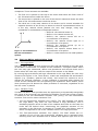
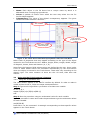
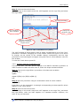
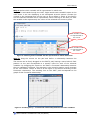
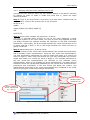
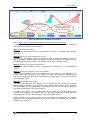
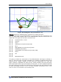
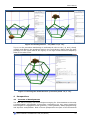
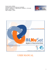
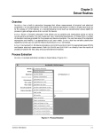
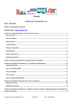
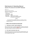
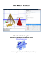
The MaLT manual Educational Technology Lab National and Kapodistrian University of Athens http://etl.ppp.uoa.gr Authors: Kynigos Chr., Moustaki Fot., Psycharis Giorgos MaLT Manual 1 Introduction MaLT is a programmable constructionist environment that allows the creation, exploration and dynamic manipulation of 3d geometrical objects. It is designed integrate the symbolic notation –in the form of Logo programs– with the dynamic manipulation of 3d geometrical objects that are graphically represented a 3d Turtle Scene. The geometrical objects visualised in the environment’s Turtle Scene are either constructed by the user when running logo procedures and commands or inserted by the user after selecting them from a library that offers numerous ready–made stereometric objects, such as cylinders and cones. Employing multiple linked representations, MaLT allows any actions performed on one of its representations to generate immediate changes to another one or the rest of its representations, providing meaningful feedback to its users. 2 Last evolutions of the DDA The MaLT environment is now using jMonkey a java based game engine that renders complex 3d scenes significantly fast, which results in boosting substantially the Turtle Scene’s performance. Therefore, any object manipulations in the Turtle Scene (direct or indirect) now provoke the environment’s immediate graphical response in speeds comparable to other 2d dynamic geometry tools. A second change made was the inclusion of a set of ready made stereometric objects and a special GUI to dynamically manipulate important features and measure areas, volumes, segments and locations. A third change was the development of a GUI to make the environment more useable and a final change was the inclusion of dynamic controllers for camera movement. The elements modified since the last deliverable and the elements introduced in the new MaLT are presented below in detail. 3 Description of the final form of the DDA The new MaLT environment consists of two main areas, the left and the right one. The left area –the larger one– constitutes the environment’s “Turtle Scene”, where user–constructed or ready–made 3d figures are graphically visualized. The component that appears on the right area, however, is of the user’s choice. By clicking on the corresponding tab on the top of the right area, the user may select between two different components to display: the Logo Editor (including the Variation Tool) and the Property Editor. 3.1 The Turtle Scene 3.1.1 Description The Scene is a 3d grid–like interface where 3d geometrical objects are graphically represented. The 3d geometrical objects that appear in the Scene are either constructed by the user when running logo procedures or inserted by the user after selecting them from a library that offers numerous ready made stereometric objects, such as cylinders, spheres and cones. The 3d turtle doesn’t appear in the Scene by default. The user must type and run, at the Logo Editor, at least one command that produces a graphical result in the Scene so as to make the turtle visible. The trace the turtle leaves when moving inside the Scene –a thin 3D cylindrical line– is selectable. Clicking on this trace causes the 1dVT tool to activate and appear on the right part of the interface, right below the Logo area. 3.1.2 Scene camera manipulation The user may look at her/his constructions inside the Scene from different EDUCATIONAL TECHNOLOGY LAB (ETL/NKUA) 2 MaLT Manual viewpoints. Three cameras are available: The first one is placed on the top of the Scene and shows the Floor View of the 3d constructions inside the Scene. The second one is placed on the one of the Scene’s sides and shows the Side View of the 3d constructions inside the Scene. The third one is the main camera of the Scene and is turned towards the negative direction of the Z axis, as shown to the XYZ representation below. It is the only camera whose position the user may change, using logo commands or combinations of keyboard buttons. Y X Z Figure 1: The semantics of the XYZ coordination system. 3.2 o Shift+W: the camera zooms in, o Shift+S: the camera zooms out, o Shift+A: the camera moves left on a circumference of a sphere, o Shift+D: the camera moves right on a circumference of a sphere o Shift+Q: the camera moves up on a circumference of a sphere o Shift+E: the camera moves down on a circumference of a sphere o Shift+X: resets camera to its initial position The Logo Editor and Variation Tools 3.2.1 The Logo Editor The Logo Editor opens up when clicking on the Logo tab situated on the right area of the MaLT environment. It consists of two interfaces: a Program Editor where the user may type commands, define new procedures and execute them and a Parser where the user may view the output of his actions on the Editor. By running logo procedures and logo commands in the Logo Editor the user may construct 3d figures in the Turtle Scene, create and manipulate 3d stereometric objects (e.g. cylinders, spheres and cones), and control the camera so as to change the selected viewpoint. A logo command is executed when placing the cursor at the command’s line and pressing the keyboard’s Insert button, while when pressing the F6 button the whole procedure is executed, regardless of the line the cursor is placed. 3.2.2 Variation Tools The MaLT Variation Tools provide users the opportunity to dynamically manipulate the values of an executed Logo procedure’s variables. In the final version of MaLT it consists of the Uni–dimensional Variation Tool (1dVT), the Two–dimensional Variation Tool and the Vector Variation Tool. The Uni–dimensional Variation Tool (1dVT): The 1dVT appears just below the Logo Editor, only after the user defines a Logo procedure, runs it attributing specific values to each of its variables and clicks on the trace the turtle has left behind when constructing the graphical outcome of the procedure in the 3d Scene. It consists of “number line”–like sliders, each of which corresponds to one of the variables used in the Logo procedure. The Two–dimensional Variation Tool (2dVT): The 2dVT allows the co– variation of two of the Logo procedure’s variables and is activated when selecting those two variables from a window that appears right next to the EDUCATIONAL TECHNOLOGY LAB (ETL/NKUA) 3 MaLT Manual 1dVT. The user decides which variable will correspond to which axis (the X or the Y) on the 2dVT’s orthogonal pad and drags the mouse on the pad’s interface to co–vary of the two variables’ values. The Vector Variation Tool (VVT): The VVT allows the co–variation of three variables by using two 2d representations of a vector defined by these variables according to an (r, φ, θ) polar semantic in the 3d space.The VVT requires a Logo procedure of at least three variables and is activated when clicking on the icon next to the 1dVT. A pop–up menu appears so as for the user to select which variable will to correlate to r, φ and θ (r stands for length, θ for the angle between the vector’s projection on the xz plane and the z–axis and φ for the angle between the vector and the xz plane). The three variables’ values can be manipulated by dragging and rotating vectors in the VVT window that appears. Figure 2: The Turtle Scene and Logo Editor in the final version of MaLT. 3.3 The Property Editor Just like the Logo tab, the Property Editor tab is situated on the right part of the new MaLT interface. It is designed to provide the user a library of ready made objects which she/he may insert in the Scene and manipulate them by editing its properties. It consists of the Toolbar, the Palette and the main area of the Property Editor. 3.3.1 The Toolbar In order to insert and manipulate ready–made objects, the user has at his disposal several features in the form of icons at the Editor’s Toolbar. These are: New Object: Clicking on the New Object icon, the Object Palette opens up and the object inserting procedure begins. Deselecting the icon the New Object procedure is aborted. Insert Object: It consummates the object insertion procedure. After the object is inserted the insert Object procedure deactivates. Delete Object: It removes the selected object off the Scene. A pop up window asks the user whether the wants to proceed or not. Unfold Object: It causes the generation of a 2d object that has the same EDUCATIONAL TECHNOLOGY LAB (ETL/NKUA) 4 MaLT Manual area as the selected object. The button is active only if there is a selected object and if the selected object can be unfolded. New Activity: It deletes any ready–made object in the Scene and begins a new activity for the user. Save: It saves the activity in an already existing file or a new file if the activity is not saved before. Save as: It saves the activity in a new file. Camera button 1 (Floor view): The floor view camera is activated or deactivated. Camera button 2 (Side view): The side view camera is activated or deactivated. Camera button 3 (Main view): The main view camera is activated or deactivated. Reset main view: Resets camera 3. Light: By clicking on this button a manipulable light source appears in the Scene. Deselecting it the light source is removed. 3.3.2 The Object Palette The Object Palette contains ready–made objects which the user may insert in the Scene using the Insert Object button. The kinds of objects the user may insert are: Spheres Cylinders Cones Pyramids Orthogons Canonical Prismatics Canonical Polygons Lines Planes Line Segments Circles The Toolbar The Palette’s available types of objects Figure 3: The Toolbar and the Object Palette. 3.3.3 Property Editor The Property Editor is activated each time the user selects a ready–made object from the 3d Scene. The type of the selected object appears in the Palette while the Property Editor’s fields –just below the Object Palette– become available to the user so as to modify the attributed values. Changing a value in one of the Property Editor’s fields produces an immediate visual result to the object inserted in the Scene. The Property Editor is also activated each time the user begins an object inserting procedure by clicking on the New Object button. Since the properties to be defined in the Property Editor are not the same for all the available types of ready–made objects, the user has to choose first from the Palette the kind of object she/he wishes to insert. The default values for the selected type appear on the Editor. The user may modify these values so as to define the kind of properties her/his object wishes to hold. Although for each type different properties appear on the Property Editor, yet, there is a set of standard properties that appear for all the types of objects. These are: EDUCATIONAL TECHNOLOGY LAB (ETL/NKUA) 5 MaLT Manual Name: Each object in the 3d Scene has a unique name by which it is addressed when running logo procedures. Colour: A palette of colours from which the user may select the one for her/his object appears. Transparency: The value of the object’s transparency appears. The given values should be between 0 and 255. The Toolbar The Palette The object’s properties to be edited The ready–made inserted object Figure 4: The Turtle Scene and the Property Editor tab in the new MaLT. Other kinds of properties that may appear according to the type of the object inserted in the Turtle Scene are the: Radius, Height, Sides, Length, Width, Length of diagonal, Centre, Point and Position (X, Y, Z). Apart from the Property fields whose values are defined by the user, there is also a set of fields whose values are calculated automatically by the environment when the object is inserted in the Turtle Scene. These also vary according to the object’s type. The most common of them are the: All Area, Side Area and Volume. 3.4 Using the MaLT Environment’s features 3.4.1 Using the 1d Variation Tool The 1dVT doesn’t appear in the MaLT’s interface by default. In order to make it visible and work with it, follow the steps mentioned below: Step 1: Type at the Logo Editor a procedure of at least one variable. to rect :a :b :c repeat 2 [fd(:a) rt(:c) fd(:b) rt(180‐:c)] end Step 2: Run the procedure using an arithmetical value for each variable. Type the procedure’s name and inside the parentheses type the arithmetic values for each variable. rect(20 30 40) Press F6 to run the command. A rectangle corresponding to these specific values appears in the Turtle Scene. EDUCATIONAL TECHNOLOGY LAB (ETL/NKUA) 6 MaLT Manual Step 3: Click on the turtle’s trace. When clicking on the turtle’s trace the 1dVT appears on the Logo Tab just below the Logo Editor. The Logo procedure The procedure’s three variables Change the variation’s step Drag the pointers to change the variables’ original values Change the range of the variation Figure 5: The 1d Variation Tool (1dVT). The 1dVT consists of three sliders, each of which corresponds to one of the “rect” procedure’s variables. Dragging one of the sliders causes the figure in the Scene to change, as the values of the variable change consequently and the logo procedure is executed again and again using each time a new arithmetic value for the variable. To clear the Turtle Scene press F5. 3.4.2 Working with the 2d Variation Tool Just like the 1dVT, the 2dVT doesn’t appear in the MaLT’s interface by default. In order to make it visible and work with it, follow the steps mentioned below: Step 1: Type at the Logo Editor a procedure of at least two variables. to rect :a :b :c up(90) repeat 2 [fd(:a) rt(:c) fd(:b) rt(180‐:c)] end Step 2: Run the procedure using an arithmetical value for each variable. rect(7 3 55) Press F6 to run the command. A rectangle corresponding to these specific values appears in the Turtle Scene. Step 3: Click on the turtle’s trace. When clicking on the turtle’s trace the 1dVT appears on the Logo Tab, just below the Logo Editor, while the 2dVT appears in a separate window. However, the 2dVT is not yet activated. EDUCATIONAL TECHNOLOGY LAB (ETL/NKUA) 7 MaLT Manual Step 4: Select which variable will be represented in which axis. The 2dVT is activated through the 1dVT. Right beside each variable’s name in the 1dVT there is an icon displaying a red orthogonal bi–axial system. Choose the vertical or the horizontal axis on the icon so as to define in which of the 2dVT’s axis the selected variable will be represented. When clicking on the axis you wish the variable to be represented, the colour of the selected axis turns to green. The variable A will be represented in the X axis. The variable B will be represented in the Y axis. Figure 6: Defining which variable will be represented in which 2dVT axis. Step 5: Drag the mouse on the pad and define a relationship between the variables The mouse can be freely dragged on the 2dVT’s pad, leaving a trace behind. Each position on the pad corresponds to a specific value for each of the selected variables. By dragging the mouse on the 2dVT a functional relationship between the two variables is defined. The changes in the mouse’s position cause changes to the 1dVT sliders’ values as well as to the figure in the Scene according to this functional relationship. The resulting line on the 2dVT’ pad corresponds to the graph of this functional relationship. Figure 7: Creating the y = x functional relationship between the two variables. EDUCATIONAL TECHNOLOGY LAB (ETL/NKUA) 8 MaLT Manual 3.4.3 Working with the Vector Variation Tool (VVT) Just like the 1dVT and the 2dVT, the VVT doesn’t appear in the MaLT’s interface by default. In order to make it visible and work with it, follow the steps mentioned below: Step 1: Type at the Logo Editor a procedure of at least three variables and run the procedure. Click on the turtle’s trace in the 3d Scene. to rect :a :b :c up(90) repeat 2 [fd(:a) rt(:c) fd(:b) rt(180‐:c)] end rect(7 3 55) Step 2: Select which variable will represent r, θ and φ. The VVT is activated when clicking on one of the icons displaying a polar coordinate system on the 1dVT slider. The pop–up menu that appears will help you define whether the selected variable will represent in the polar coordinate system the r (the length), the θ (the angle between the vector’s projection on the xy plane and the x–axis) or the φ (the angle between the vector and the xy plane) coordinate. Step 3: Manipulating the r, θ and φ values. The VVT consists of two vector–like representations (the constituent projections) and a resultant vector representation. Using the first vector–like representation, you may dynamically manipulate the vector’s length and rotate it to control the value of angle θ, while using the second one you may manipulate the vector’s length and rotate it to control the value of angle φ. The changes performed on the two vector–like representations are reflected on the resultant vector representation, which is not available for direct manipulations. The polar and the Cartesian values are represented graphically by the vectors their selves and their projections and numerically in the text boxes just below the vectors. Any manipulations performed to the vector presentations are visualised in the Turtle Scene as the figure constructed changes dynamically. Click on the variable’s polar coordinate icon Choose whether A will be represented by r, θ or φ. Figure 8: Opening up the Vector Variation Tool. EDUCATIONAL TECHNOLOGY LAB (ETL/NKUA) 9 MaLT Manual The text boxes show the r, θ, φ, x, y and z values Drag and rotate the vectors to change the r, θ and φ coordinates Figure 9: The Vector Variation Tool (VVT). 3.4.4 Inserting and manipulating ready–made stereometric objects To insert ready made objects in the Turtle Scene, click on the Property Editor tab and follow the steps mentioned below. Step 1: Activate the Editor. Click on the New Object icon on the Editor’s Toolbar to initialise the inserting procedure. Step 2: Select the type of object to insert. Choose from the Palette’s pop–up menu the type of object you wish to insert in the Turtle Scene. Notice that the properties on the area below the Palette change according to the type of object you choose. Choose for example a cone Step 3: Define your object’s properties. Define your object’s Name, Colour, Transparency, Position (X, Y, Z), Radius and Height. Step 4: Insert your object in the Turtle Scene. Press the Insert Object icon on the Toolbar so as to make the cone appear in the Turtle Scene. After inserting the object, the MaLT environment calculates the object’s All Area, Side Area and Volume and provides their values on the Editor’s corresponding fields. Step 5: Manipulate your object. The little white spheres that appear on your object are its handles. By clicking and dragging a handle you may modify your object’s dimensions. These changes become visible not only graphically in the Scene but also on the Editor’s fields as the Radius and Height values also change. To move your object in the XY plane click at any point on its surface and drag it towards the direction you wish to move it. By using both the left and the right mouse button you may also drag your object along the Z axis. When clicking at any point of the Scene the object is deselected, its handles disappear and its surface appearance turns from grid–like to solid–like. To select it again, just click on it. EDUCATIONAL TECHNOLOGY LAB (ETL/NKUA) 10 MaLT Manual Edit the values to change the cone’s properties Click on the handles and drag them to change its dimensions Figure 10: A cone inserted in the Turtle Scene. The Property Editor’s objects can also be inserted through the Logo Editor using logo commands, specialised for each type of object. 3.4.5 Manipulating the camera viewpoints In the new MaLT environment the user has at his disposal three cameras. Each one offers a different viewpoint of the ready–made and logo–constructed geometrical objects in the environment’s Turtle Scene. The selection of the viewpoint from which you may observe your constructions is performed through the Property’s Editor Toolbar. Click on 1, 2 or 3 to select the viewpoint Figure 11: The third camera is currently activated in the Property Editor’s Toolbar. Camera 1 is placed on the top of the Scene and shows the Floor View of the constructions inside the Scene. Camera 2 is placed on the one of the Scene’s sides and shows the Side View of the constructions inside the Scene. Camera 3 is the main camera of the Scene and is turned towards the negative direction of the Z axis. It is the only camera whose position the user may change, using logo commands or combinations of keyboard buttons. EDUCATIONAL TECHNOLOGY LAB (ETL/NKUA) 11 MaLT Manual 1 2 3 Figure 12: The Camera 1, Camera 2 and Camera 3 viewpoint. 3.4.6 Creating logo–constructed 3d stereometric objects In the MaLT environment the user may also construct complex stereometric objects using simple logo commands and procedures. Follow the steps mentioned below to construct a dodecahedron. Step 1: Define the “Pentagon” procedure to create a pentagon The dodecahedron will consist of 12 facets each of which will have the shape of a pentagon. The following procedure describes the turtle moves to be performed so as to create a pentagon: (line 1) (line 2) (line 3) (line 4) to pentagone :a repeat 5 [ fd(:a) rt(72)] end (line 5) pentagone(3) The pentagon will be constructed as the turtle will repeat 5 times (line 2) the procedure: fd(:a) rt(72). The turtle will move forward maintaining its direction by a number of pixels that will be defined by the (:a) variable. As the pen is down, the turtle will draw a line whose length will be (:a) pixels. After moving for (:a) pixels, the turtle will turn clockwise by 72 degrees. As the fd(:a) rt(72) repeats 5 times a pentagon whose sides is (:a) pixels long will appear. Try to run the procedure attributing an arithmetical value to the (:a) variable (e.g. 3, line 5) and observe the graphical result in the Turtle Scene. EDUCATIONAL TECHNOLOGY LAB (ETL/NKUA) 12 MaLT Manual Figure 13: Running 5 times the fd(:a) rt(72) procedure (a = 3). Step 2: Define the “cup” procedure to create six adjacent pentagons For the construction of the bottom half of the dodecahedron six pentagons will be needed. The next procedure will help you create 6 adjacent pentagons forming a kind of “cup”. The dihedral angle between two adjacent pentagons for the formation of a dodecahedron equals to 2*arccos(0.5/sin(72)). (line 6) (line 7) (line 8) (line 9) (line 10) (line 11) (line 12) (line 13) to cup :a repeat 5 [ rr(2*arccos(0.5/sin(72))) pentagone(:a) lr(2*arccos(0.5/sin(72))) fd(:a) rt(72)] end cup(3) The bottom part of the dodecahedron will be constructed as the turtle will repeat 5 times (line 7) the procedure: (line 8) (line 9) (line 10) (line 11) rr(2*arccos(0.5/sin(72))) pentagone(:a) lr(2*arccos(0.5/sin(72))) fd(:a) rt(72) EDUCATIONAL TECHNOLOGY LAB (ETL/NKUA) 13 MaLT Manual Initially, the turtle will rotate to the right by 2*arccos(0.5/sin(72)) degrees (i.e the degrees of the dodecahedron’s dihedral angle) (line 8). The pentagon procedure will be executed and the first pentagon will appear. It’s side length will be defined by the (:a) variable (line 9). The turtle will then return to the position it held before the execution of the pentagon procedure. The turtle will rotate to the left by 2*arccos(0.5/sin(72)) degrees (i.e the degrees of the dodecahedron’s dihedral angle) (line 10). It will then move forward by a number of pixels that will be defined by the (:a) variable and turn clockwise by 72 degrees. Figure 14: Running lines 8 – 11. Try to run the procedure attributing an arithmetical value to the (:a) variable (e.g. 3, line 8) and observe the graphical result in the Turtle Scene. Notice that the sixth pentagon (the one on the base of the figure) is not logo–constructed but shaped by the other five ones. EDUCATIONAL TECHNOLOGY LAB (ETL/NKUA) 14 MaLT Manual Figure 15: Running the “cup” procedure (a = 3). Step 3: Define the “dodecahedron” procedure to create the figure For the construction of the dodecahedron you will need two “cup” procedures. The first one will create bottom half of the dodecahedron and the second one the upper half. The upper half will be a reversed “cup”. (line 14) (line 15) (line 16) (line 17) (line 18) (line 19) (line 20) (line 21) (line 22) (line 23) (line 24) (line 25) to dodecahedron :a :theta rt(:theta) cup(:a) rt(18) up(2*arccos(0.5/sin(72))) lt(18) fd(:a) lt(18) dp(180‐2*arccos(0.5/sin(72))) lt(18) rt(108) fd(:a) lt(72) fd(:a) rt(18) dp(180‐2*arccos(0.5/sin(72))) rt(18) rr(180) cup(:a) end dodecahedron(3 0) The point at which the construction of the dodecahedron will begin is defined in line 10. The turtle will turn right clockwise by a number of degrees that will be defined by the (:theta) variable. At that point the construction of a “cup” will begin. However, regardless the value of the (:theta) variable, the turtle will finish the construction of the cup at the bottom of the figure. To move upwards and find the right node so as to start the construction of the upper cup, the turtle will need to move according to lines 17–21. To avoid creating unnecessary lines, it will have to move on the bottom cup’s existing lines. EDUCATIONAL TECHNOLOGY LAB (ETL/NKUA) 15 MaLT Manual Figure 16: Running lines 17 – 21 (theta = 0, a = 3). Try to run the procedure attributing an arithmetical value to the (:a) and (:theta) variable and observe the graphical result in the Turtle Scene. Notice that the sixth pentagon on the upper base of the figure) is not logo–constructed but shaped by sides of the other ones. Figure 17: Running the “dodecahedron” procedure (theta = 0, a = 3). 4 4.1 Perspectives In terms of developments The idea was to employ new technologies emerging for 3d animations to develop a mathematical microworlds environment integrating the two most prominent technologies for engagement with geometry, turtle geometry based programming and dynamic manipulation. Both of these perspectives are part of the theoretical EDUCATIONAL TECHNOLOGY LAB (ETL/NKUA) 16 MaLT Manual perspective developed at ETL to engage in design research involving interventions in classrooms aiming to immerse students in constructionist mathematics including the use of formalism to generate mathematical meanings. The main problems met in the process of developing the software were due to the need to connect 3d engines to java based programming and develop a logo language with java to construct and manipulate models. The best available 3d engine originally was “3impact” which we had identified before the beginning of the project and ported a Delphi programming language to build custom 3d models. In ReMath we thus needed to change the language to java so as to have multiple windows and dynamic manipulation. The manipulation however was very slow due to fragmentation in the design of the different compartments of the software. We thus identified a recently available new 3d engine and ported the java–logo components on to that with highly improved results. We also created a better GUI to make the software more stable. The prospect is to use this in the future as a base for a larger variety of programmable mathematical and scientific models and expand to include games, hopefully playable by many on the web. 4.2 In terms of deployment In the time of the project we used MaLT as one of the main pieces of software taught in two regular master’s courses (titled Methodology and Didactics of Mathematics and Didactics of Special Subjects with new Technologies respectively). We also used MaLT in a large–scale initiative of the Ministry of Education targeting 4000 mathematics teachers to receive a 96 hour course in using digital media in the teaching of mathematics. We were part of a project within this initiative to train 100 mathematics teacher educators and carried out a 350 hour course to 20 of them and took part in the teaching of all the others. MaLT featured as the 3d version of Turtleworlds an ETL designed widely available software. We made MaLT available on the ETL website and advertised it as a resource in these courses. EDUCATIONAL TECHNOLOGY LAB (ETL/NKUA) 17