1
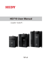
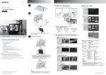
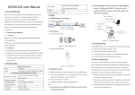
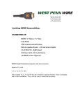
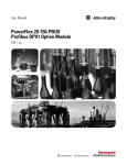
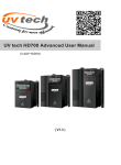
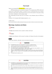
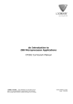
HDOM-Profibus-V0 User Manual (V1.0) HEDY Industry Automation Control Co., Ltd. Contents 1 Introduction .......................................................... 1 1.1 Product description .............................................1 1.2 HDOM-Profibus-V0 label ....................................1 1.3 Technical specifications ......................................1 2 Mechanical installation ......................................... 3 2.1 HD700 drive Extended Capabilities Port .............3 2.2 Dimensions .........................................................3 2.3 Installation ..........................................................3 3 Electrical installation ............................................. 4 3.1 HDOM-Profibus-V0 module ................................4 3.2 PROFIBUS-DP connectors ....................................5 3.3 PROFIBUS-DP cable .............................................6 3.4 PROFIBUS-DP network termination ....................6 3.5 PROFIBUS-DP cable shielding .............................6 4 Getting started ...................................................... 7 4.1 Parameter setting step .......................................7 4.2 Parameter descriptions .......................................8 5 Data format ........................................................ 16 5.1 Cyclic PPO data word ........................................17 5.2 Non-cyclic PPO data word ................................18 5.3 PPO format .......................................................18 6 Control and status words .................................... 22 6.1 Control word .....................................................22 6.2 Status word .......................................................24 6.3 HD700 drive fieldbus reference channel and frequency actual value ...........................................25 6.4 Scaling definition ..............................................26 7 GSD files ............................................................. 26 8 Parameter list ..................................................... 27 1 Introduction 1.1 Product description PROFIBUS-DP (Decentralized Peripherals) is used to operate sensors and actuators via a centralized controller in production (factory) automation applications. The HDOM-Profibus-V0 is a fieldbus Solutions Module that can be installed to the expansion slot(s) in HD700 drives to provide PROFIBUS-DP slave connectivity. The HDOM-Profibus-V0 module is suitable for HD700 drives that the control panel software version is V1.04 and above. The drives that the control panel software version is below V1.04, menu P19 parameters are not seen. If you have any questions, please contact your nearest representative or call the technical support hotline: +86-4007-000-885. 1.2 HDOM-Profibus-V0 label Module name Serial number Software version CE approval 1.3 Technical specifications 1) Data rate and range HDOM-Profibus-V0 automatically detects and adapts the data rate. Supported data rates (kbits/s) and range as follows: Rate (kbit/s) Range (m) 12000 6000 3000 1500 500 187.5 93.75 45.45 100 100 100 200 Table 1-1 400 1000 1000 Data rate and range 1 1000 19.2 9.6 1000 1000 2) Support five types of PPO (Parameter Process data Object PPO1-PPO5) data format. 3) Support Profibus DP V0 protocol. 4) The HDOM-Profibus-V0 is powered from the host drive’s internal power supply. The module output meets SELV safety level. 2 2 Mechanical installation 2.1 HD700 drive Extended Capabilities Port The HD 700 drive has an expansion slot to make the HDOM-Profibus-V0 module installed on the drive. The installation of HDOM-Profibus-V module is illustrated in Figure 2-1. CN2 slot Figure 2-1 The expansion slot CN2 2.2 Dimensions Model name H (mm) W (mm) D (mm) HDOM-Profibus-V0 70 45 23 2.3 Installation 1) Before installing the HDOM-Profibus-V0 module in any drive, ensure the AC supply has been disconnected for at least 10 minutes. 2) Check the module appearance. Please contact the supplier if there is any breakage. 3) Remove the drive terminal cover. 4) CN2 port has a plastic protective cover, please carefully cut it off. 5) Direct the back of the module to CN2. 6) Push this module into the CN2 slot located on the drive. 3 3 Electrical installation 3.1 HDOM-Profibus-V0 module The HDOM-Profibus-V0 has a standard 9-way female D-type connector for the PROFIBUS-DP network, as shown in the figure 3-1. Figure 3-1 HDOM-Profibus-V0 terminals Figure 3-2 HDOM-Profibus-V0 D-type connector pin out Descriptions of D-type connections are shown in the table 3-1. D-type terminal Function 1 PGND 2 NC 3 Positive data line (B) - Red 4 NC 5 GND isolated 6 +5V isolated 4 D-type terminal Function 7 NC 8 Negative data line (A) - Green 9 NC Table 3-1 D-type connections 3.2 PROFIBUS-DP connectors There are many manufacturers of PROFIBUS-DP connectors. Always ensure that any connectors used on the network are fully approved for use with PROFIBUS-DP. Some of the connector types available include built in termination that allows the network to be isolated, this can be very useful when fault finding. Note: Some connectors are incompatible with HDOM-Profibus-V0. Siemens connectors that part number are 6GK1500-0FC00 and 6GK1500-0EA00 can be used with HDOM-Profibus-V0 connection. 5 3.3 PROFIBUS-DP cable PROFIBUS-DP cable is a bulk shielding twisted-pair cable. PROFIBUS-DP networks can run at high data rates and require cable specifically designed to carry high frequency signals. Low quality cable will attenuate the signals, and may render the signal unreadable for the other nodes on the network. Cable specifications and a list of approved manufacturers of cable for use on PROFIBUS-DP networks are available on the PROFIBUS Nutzerorganization (PNO) web site at www.profibus.com. 3.4 PROFIBUS-DP network termination It is very important in high-speed communications networks that the network communications cable is installed with the specified termination resistor network at each end of each segment. This prevents signals from being reflected back down the cable and causing interference. Siemens connectors have the internal termination resistors and switch. The switch can enable or disable the internal resistors. 3.5 PROFIBUS-DP cable shielding Correct shielding of the PROFIBUS-DP cable is required for reliable operation at high data rates; this can be achieved by exposing the cable shield of each PROFIBUS-DP cable and ensuring that they are clamped to the drive grounding metalwork as close as possible to the drive termination. Good ground connection can enhance the noise immunity of the system. When laying the PROFIBUS-DP cables, we should pay attention to the following matters: Do not directly lay against or parallel the power cable. PROFIBUS-DP cable and power cable are laid in their respective cable trough. The cable shield of each PROFIBUS-DP cable should ground as large as possible contact surface. 6 4 Getting started 4.1 Parameter setting step 1) The drive power on, access menu P19. At this time only P19.01 can be seen. Set P19.01 to 101, and then other parameters can be seen. P19.01=101 means that the option module is HDOM-Profibus-V0 module. 2) Set node address. Set node address parameter P19.02 (the default value is 124). 3) Set endian format according to the master. Set P19.08: set P19.08 to 0, High byte first Low byte second (default). Set P19.08 to 1, Low byte first High byte second. 4) Set data format. Set P19.09: 1-5 respectively correspond to PPO1-5. The default value of P19.09 is 3, select PPO3. 5) Set the trip time at communication interruptions. Set P19.07: the default value is 200 and the unit is millisecond (if detected PROFIBUS-DP network interruptions, the drive will stop according to P03.10 setting). Set P19.07 to 0, the function is disabled. The communication interruptions will not force the drive to stop. 6) The drive power off. Install the HDOM-Profibus-V0 and the drive power on. 7) At the beginning, the module indicator light displays red. This means communication has not been set up. 8) When the indicator light turns on green, the communication has been set up. 9) If the indicator keep on red (about 1-5 minutes), please check P19.05 and P19.06. According to the P19.05 and P19.06 descriptions check relevant configuration and installation. 10) If the indicator light flash red and green alternately, it means that the PROFIBUS-DP network trips. Please check the network connections (fieldbus connector or fieldbus cables). 7 4.2 Parameter descriptions The following parameter description includes: Parameter ID: parameter code Parameter name: simple explanation of the parameter Parameter range: This gives the range of the parameter and the values it can be adjusted to. In 【 】 is the default value. Change mode: defines if the parameter can be modified and the parameter can be modified in what circumstances. Stop Only Write & Read can be done only at stopping. Actual Read only Parameter ID Parameter name Range【Default】 Change mode P19.01 Module ID code 0−255【0】 Stop Only The module ID code for HDOM-Profibus-V0 is 101. Parameter ID Parameter name Range【Default】 Change mode P19.02 Node address 0−125【124】 Stop Only Node address setting. Every node on a PROFIBUS-DP network must be given a unique network node address. Parameter ID Parameter name Range【Default】 Change mode P19.03 Network data rate 0−9,15 Actual The PROFIBUS-DP network data rate is controlled by the master controller. The HDOM-Profibus-V0 will automatically detect the PROFIBUS-DP network data rate and synchronize to it. P19.03 will indicate the data rate that has been detected by the HDOM-Profibus-V0. A value of 15 indicates that the HDOM-Profibus-V0 has not detected any activity on the PROFIBUS-DP network and is waiting for the master controller to start communicating. P19.03 Bit/s 15 Auto-detecting 0 12M 8 P19.03 Bit/s 1 6.0M 2 3.0M 3 1.5M 4 500k 5 187.5k 6 93.75k 7 45.45k 8 19.2k 9 9.6k Parameter ID Parameter name Range【Default】 Change mode Re-initializing P19.04 0−1【0】 Stop Only PROFIBUS-DP network Changes to the HDOM-Profibus-V0 configuration will not take effect until the PROFIBUS-DP network has been re-initialized. To re-initialize the PROFIBUS-DP network: Set P19.04 to 1. Pressing the PRG key, when the sequence has been completed, P19.04 will be reset to 0 automatically. Note: This sequence does NOT store the HDOM-Profibus-V0 configuration parameters in the HDOM-Profibus-V0 EEPROM. Parameter ID Parameter name Range【Default】 Change mode P19.05 Operating status 0−4【0】 Actual P19.05 Parameter Description Indicates that HDOM-Profibus-V0 is not installed 0 No module detected in the drive. Indicates that MCU has been initialized MCU has been 1 correctly, and is waiting for the PROFIBUS-DP initialized master to initialize communications. 9 P19.05 2 Parameter Description PROFIBUS-DP Indicates that PROFIBUS-DP master has been master has been initialized correctly, and is detecting baud rate. initialized Indicates that PROFIBUS-DP master has Baud rate has been 3 detected baud rate correctly, and is waiting for detected parameter message and configuration message. Indicates that the PROFIBUS-DP master has 4 Data transfer established communications with the HDOM-Profibus-V0. Parameter ID Parameter name Range【Default】 Change mode 0−8【0】 Actual HDOM-Profibus-V0 P19.06 error codes If the HDOM-Profibus-V0 detects an error during operation, it will force a trip on the drive and update the error code parameter, P19.06. The following table shows the possible HDOM-Profibus-V0 error codes. Error Fault Description code Indicates that the HDOM-Profibus-V0 module 0 No error detected is ok. It is possible to trip the drive externally via various communication channels. MCU out of memory Indicates that MCU of the HDOM-Profibus-V0 1 initialization sequence was not successful. 2 Memory check error Memory check error 3 Parameter overrun HDOM-Profibus-V0 parameter setting error 4 Configuration error 5 Configuration error 6 Network interruptions Node address P19.02 and node address of master configuration are different. PPO and P19.09 data format are different. When watchdog time-out has occurred, PROFIBUS-DP network is interrupted. 10 Error Fault Description code Internal The drive and HDOM-Profibus-V0 communication error communications stop. EEPROM read-write HDOM-Profibus-V0 module cannot load or error read data from EEPROM. 7 8 Note: These faults can only be looked up in this parameter. P19.04 can reset faults 2 to 6. P19.29 can reset all faults. Suggest that using P19.04 reset faults 2 to 6 at first. Parameter ID Parameter name Range【Default】 Change mode 0−3000ms【200】 Stop Only Trip time set at P19.07 communication interruptions When the drive detects the PROFIBUS-DP network interrupted or communicates with HDOM-Profibus-V0 stopping, communications fail to restore within setting time, and then the drive will stop. If P19.07 is set to 0, the function is disabled. The communication interruptions will not force the drive to stop. The unit is millisecond (ms). Parameter ID Parameter name Range【Default】 Change mode P19.08 Data endian select 0−1【0】 Stop Only The parameter is used to select data endian format. Most PROFIBUS-DP master controllers use big endian format (High byte first Low byte second) by default, many also support little endian (Low byte first High byte second), however some older PLCs do not offer the facility to select big endian format. Please contact the master controller supplier to know the data endian format that can be used. 0: High byte first Low byte second (default) 1: Low byte first High byte second 11 Parameter ID Parameter name Range【Default】 Change mode P19.09 PPO select 0−5【3】 Stop Only The parameter is used to select type of Parameter Process data Object (PPO). There are five types. The default PPO type is PPO3. Please set the parameter according to the PPO type of the master controller configuration. See Chapter 5 Data format for more information. Parameter ID Parameter name Range【Default】 Change mode 00.00−18.08 P19.10−P19.17 Cyclic data IN channel Stop Only 【00.00】 Cyclic data OUT 00.00−18.08 channel 【00.00】 P19.18−P19.25 Stop only Cyclic data IN and OUT channel According to the PPO type of configuration, these parameters are mapped to cyclic PPO data words 2 to 9. See Chapter 5 Data format for more details. Parameter ID Parameter name Range【Default】 Change mode P19.26 Restore defaults 0−1【0】 Stop Only If the host drive is defaulted it will also clear the current configuration for the slot HDOM-Profibus-V0 is installed to. Setting P19.26 to 1 additionally clears the backup copy of the HDOM-Profibus-V0 configuration stored in the module. This can be performed as follows: Stop the drive (if the motor is running). Set P19.26 to 1. Press PRG key, and the HDOM-Profibus-V0 will reset using the default values. P19.26 will be reset to 0 automatically. Set P19.04 to 1, and the PROFIBUS-DP network will re-initialise using the default value after pressing PRG key. P19.04 will be reset to 0 automatically. 12 Parameter ID Parameter name Range【Default】 Change mode Store P19 parameters to P19.27 HDOM-Profibus-V0 0−1【0】 Stop Only EEPROM P19 parameters are stored in the host drive EEPROM and HDOM-Profibus-V0 will always use these values during initialisation to configure itself. Using P19.27 (if P19.27 is set to 1) it is possible to store the parameter configuration as a backup copy in the HDOM-Profibus-V0 EEPROM. This allows the module to contain a backup copy of its configuration that may be restored using P19.28 (for details please refer to the description for P19.28). This is of particular use when setting up a module to send to site as a replacement or as a method of keeping a backup copy of the HDOM-Profibus-V0 settings that may be used in the event of a drive failure. Storing the parameter configuration to HDOM-Profibus-V0 module may affect PROFIBUS-DP network communications, but the impact time is usually very short and then the communications will automatically return to normal. To store HDOM-Profibus-V0 parameters in the HDOM-Profibus-V0 EEPROM: Stop the drive (if the motor is running). Set P19.27 to 1. After pressing PRG key, P19 parameters store to the HDOM-Profibus-V0 module from the drive EEPROM. P19.27 will be reset to 0 automatically. The drive will perform a drive save and copy the settings from the slot menu associated with the HDOM-Profibus-V0 into the HDOM-Profibus-V0 EEPROM. 13 Parameter ID Change Range【Default】 Parameter name mode Restore the previous parameter configuration from P19.28 0−1【0】 Stop Only HDOM-Profibus-V0 EEPROM When P19.28 is set to 1 (ON), the HDOM-Profibus-V0 will transfer the configuration parameters from its EEPROM to the host drive over-writing the existing values in the host drive. Then set P19.04 to 1 and PROFIBUS-DP network will re-initialize. The full sequence of events for restoring values from a HDOM-Profibus-V0 is as follows: Stop the drive (if the motor is running). Set P19.28 to 1. Press PRG key and the HDOM-Profibus-V0 will overwrite all P19 parameters with the values stored in its EEPROM. P19.28 will be reset to 0 automatically. Set P19.04 to 1 or restart the drive, and re-initialize PROFIBUS-DP network. P19.04 will be reset to 0 automatically. Parameter ID Parameter name Range【default】 Change mode Re-initializing the P19.29 0−1【0】 Stop Only HDOM-Profibus-V0 When there is an error between HDOM-Profibus-V0 and the drive communications (P19.06=7), using P19.29 can re-initialize HDOM-Profibus-V0 without having to make the drive to power on. To re-initialize HDOM-Profibus-V0: Set P19.29 to 1. When the sequence has been completed, P19.29 will be reset to 0. The HDOM-Profibus-V0 will re-initialise using the updated configuration. Note: Using this function will make PROFIBUS-DP network re-initialized. 14 Using this function will reset the faults P19.06 displaying. See the description for P19.06. Parameter ID Parameter name Range【default】 Change mode HDOM-Profibus-V0 00.00−02.99 software version 【00.00】 P19.30 Actual 00XX: indicates that the Profibus module supports Profibus DP V0. 01XX: indicates that the Profibus module supports Profibus DP V0, V1. 02XX: indicates that the Profibus module supports Profibus DP V0, V1, V2. XX: indicates Profibus software version. Parameter ID Parameter name Range【default】 Change mode HDOM-Profibus-V0 00.00−99.99 firmware version 【00.00】 P19.31 15 Actual 5 Data format Note: The term OUT data refers to data that is transmitted out of the master to the slave. The term IN data refers to data that is returned from a slave into the master. HDOM-Profibus-V0 supports Profibus DP V0 protocol (The subsequent version will support Profibus DP V1, V2). Cyclic data transfer occurs between HDOM-Profibus-V0 and PROFIBUS-DP master controller. The data be defined as (Parameter Process data Object) PPO. HDOM-Profibus-V0 supports all five types of PPO: PPO1−PPO5, as table 4-1 shows: Parameter data PPO Acyclic PPO data word type Word 0 Word 1 Word 2 Word 3 PPO1 PPO2 PPO3 PPO4 PPO5 PPO5 Process data PPO type Cyclic PPO data word Word Word Word Word Word Word Word Word Word 0 1 2 3 4 5 6 7 8 Word 9 PPO1 PPO2 PPO3 PPO4 PPO5 PPO5 Table 4-1 PPO types The Black blocks indicate the data length of different PPO types. PPO1: parameter data contain 4 acyclic PPO data words, and process data contain 2 cyclic PPO data words. 16 PPO2: parameter data contain 4 acyclic PPO data words, and process data contain 6 cyclic PPO data words. PPO3: parameter data contain 0 acyclic PPO data word, and process data contain 2 cyclic PPO data words. PPO4: parameter data contain 0 acyclic PPO data word, and process data contain 6 cyclic PPO data words. PPO5: parameter data contain 4 acyclic PPO data words, and process data contain 10 cyclic PPO data words. 5.1 Cyclic PPO data word The process data is defined as cyclic PPO data word. Cyclic data transfer is a method of transferring data on a regular time period, often known as ‘polled data’. High-speed data transfer is achieved by transmitting only data bytes over the PROFIBUS-DP network and using local mapping information within the HDOM-Profibus-V0 and PROFIBUS-DP master controller to ensure that the correct data is sent to the correct locations. The flexibility of the HDOM-Profibus-V0 means that each cyclic data OUT channel can be directed to any read/write drive parameter. Similarly each cyclic data IN channel can use any drive parameter as a source of data. HDOM-Profibus-V0 The cyclic PPO data words of PPO1-PPO5 have different length, but contain two words at least: word 0 and word 1. The two words are mapped to specified parameters and cannot be changed by the user. Output: word 0 is a control word, and word 1 is frequency set value. Input: word 0 is a status word, and word 1 is frequency actual value. The user can define other cyclic PPO data words mapped to other parameters. When the user configures these words, it will take effect immediately if PROFIBUS-DP communication has been established. Therefore, PROFIBUS-DP master controller can only access to cycle PPO data word mapping internal parameters. 17 5.2 Non-cyclic PPO data word The parameter data is defined as non-cyclic PPO data word. Non-cyclic data allows access to any parameter without the need to use cyclic data transfers. This is particularly useful when accessing many different parameters for setup or archiving of drive settings. Only PPO1, PPO2 and PPO5 have non-cyclic PPO 4 data words. 5.3 PPO format PPO IN and OUT data formats are the same. Parameter data: OUT data is the request access to parameter. IN data is the response to the request returned into the master. Process data: The term OUT data refers to data that is transmitted out of the master to the slave. The term IN data refers to data that is returned from a slave into the master. There is no request and response relationship between OUT and IN data. 5.3.1 Parameter data format The parameter data format (PPO1, PPO2 and PPO5) as follows: Function OUT data word Non-cyclic PPO word 0 Non-cyclic PPO word 1 B15−b12 B11−b8 B7−b0 TASK ID Reserved MENU PARAMETER Non-cyclic PPO word 2 DATA HIGH word Non-cyclic PPO word 3 DATA LOW word Reserved The PPO 4 Word protocol is controlled by the TASK ID and RESPONSE ID; the TASK ID specifies the transaction required and the remainder of the data words carry the data for the transaction. Table 8.9 lists the possible TASK ID codes. Word 0 HIGH 4 bits refer to the TASK ID. When TASK ID = 5H, is reading request. When TASK ID = 6H, is writing request. Bit 8-11 are reserved. Word 0 low bits refer to MENU number. 18 Word 1 HIGH bits refer to the parameters accessed to. LOW bits are reserved. The definition of a data word is 16 bits. Word 2 and 3 constitute double words (32 bits), so there is no need to operate word 2 (DATA HIGH word). At reading operation, word 2 and 3 are irrelevant. At writing operation, word 3 data is written to the request parameter. Function IN data word Non-cyclic PPO word 0 B15-b12 B11−b8 RESPONSE ID Reserved B7−b0 MENU RESPONSE Non-cyclic PPO word 1 PARAMETER STATUS Non-cyclic PPO word 2 DATA HIGH word Non-cyclic PPO word 3 DATA LOW word Word 0 high 4 bits refer to RESPONSE ID. RESPONSE ID = AH, reading response. RESPONSE ID = BH, writing response. Bit 8-11 are reserved. Word 0 low bits refer to MENU number. Word 1 HIGH bits refer to the parameters accessed to. Low bits refer to the response status to the master request. The RESPONSE ID indicates the success or otherwise of the requested transaction. The possible RESPONSE ID codes: 05H: The parameter that the master access to does not exist. 06H: At writing operation, the written value exceeds the maximum or minimum value of the accessed parameter. 07H: Error - read only parameter. Target parameter specified is read only, and cannot be modified. 08H: The operation is unsuccessful. 09H: The operation is successful. The definition of a data word is 16 bits. Word 2 and 3 constitute double words (32 bits), so there is no need to operate word 2 (DATA HIGH word). At writing operation, word 2 and 3 are irrelevant. At reading operation, word 2 data is invalid and word 3 data is returned to the master. 19 For example: The master read the parameter P04.01, P04.01=5.00Hz: Parameter data output is: Word 0: 5004H (read menu P04) Word 1: 0100H (access parameter P04.01) Word 2: 0000H (no need to operate) Word 3: 0000H (no need to operate) After reading successfully, parameter data input is: Word 0: A004H (read menu P04) Word 1: 0109H (access parameter P04.01 successfully) Word 2: 0000H (invalid data) Word 3: 01F4H=500D (P04.01=5.00Hz, frequency scaling is 1:100) Note: Reserved, irrelevant, invalid or needless operating data is dealt as 0. If RESPONSE STATUS ≠9, the returned word 2 and 3 are invalid data. 5.3.2 Process data format Process data format as follows: OUT data PPO1 PPO2 PPO3 Process data (cyclic PPO data word) Word Word 0 1 word 3 4 word set word Control Frequency word set 7 8 9 - mapping using P19.10 to P19.13 - set set 6 User configurable Control Frequency Frequency 5 - set Control Frequency Control PPO5 2 Control Frequency word PPO4 Word Word Word Word Word Word Word Word User configurable mapping using - P19.10 to P19.13 User configurable mapping using P19.10 to P19.17 20 Word 0 and 1 are mapped to a drive control word and frequency set parameter and this cannot be modified. User can define other words mapping to any other parameter using P19.10 to P19.17 according to the selected PPO types. IN data PPO1 PPO2 PPO3 PPO4 PPO5 Process data (cyclic PPO data word) Word Word 0 1 Status Actual word frequency Word Word Word Word Word Word Word Word 2 3 4 5 6 Actual User configurable mapping word frequency usingP19.18 to P19.21 Status Actual word frequency Status Actual User configurable mapping word frequency using P19.18 to P19.21 Actual word frequency 8 9 - Status Status 7 - - User configurable mapping using P19.18 to P19.25 Word 0 and 1 are mapped to a drive status word and frequency actual value parameter and this cannot be modified. User can define other words mapping to any other parameter using P19.18 to P19.25 according to the selected PPO types. 21 6 Control and status words 6.1 Control word The user can use communication control word parameter P03.27 controlling the drive, such as run and direction. Process data OUT data word 0 (OUT cyclic PPO data word 0) is directly mapped to P03.27 and cannot be modified. To enable the word, the user must set control word enable parameter P03.28 to 1 and set control mode parameter P00.03 (P10.07) to 2 (communications control mode). See HD700 user manual or HD700 advanced user manual for more information. Control word P03.27 bit functions are shown in the following table. Bit Function Description Set to 1 to enable the drive. Resetting to 0 will 0 ENABLE immediately disable the drive, and the motor will coast to a stop. The lowest priority operation instruction. Set to 1 to run the motor in the forward direction. When 1 RUN reset to 0, the drive will decelerate the motor to a controlled stop. ( with RUN FWD/REV is not set to 1) 3-wire enabled. In the communication control 2 NOT STOP mode, this bit is meaningless. Set to 1 (with ENABLE set to 1) to run the motor in the forward direction. When reset to 0, the 3 RUN FWD drive will decelerate the motor to a controlled stop. Set to 1 (with ENABLE set to 1) to run the motor in the reverse direction. When reset to 0, the 4 RUN REV drive will decelerate the motor to a controlled stop. 22 Bit Function Description This signal needs to be used in conjunction with the RUN bit set to 1. Set to 1 to select the 5 FWD/REV reverse direction. Set to 0 to run in the forward direction. The RUN signal is used to start and stop the motor. Set to 1 to jog the motor forward. When reset to 6 JOG FWD 0, the drive will decelerate the motor to a controlled stop. Set to 1 to jog the motor reverse. When reset to 7 JOG REV 0, the drive will decelerate the motor to a controlled stop. A 0-1 transition of the RESET bit will reset the 8 RESET drive from a trip condition. ( If the reason for the trip disappears and the trip code < F030 ) Saving A 0-1 transition of bit 9 will store the parameters 9 parameters Trip recording to EEPROM. A 0-1 transition of bit 10 will reset the trip 10 reset recording. Enable comms to A 0-1 transition of bit 11 will enable the function write parameters selector parameters. 11 12-15 Reserved − P03.27 commonly used Settings as follows (only list low 8 bit), can be used directly: P03.27=1 (00000001) enable P03.27=8 (00001000)or P03.27=2 (00000010) run forward P03.27=16 (00010000)or P03.27=34 (00100010) run reverse P03.27=64 (01000000) jog forward P03.27=128 (10000000) jog reverse Please see description for P03.27 in HD700 advanced manual for further details. 23 6.2 Status word HD700 drive status word parameter P10.14 indicates the drive’s state of health and operational condition, such as drive ok, drive at speed, etc. Process data IN data word 0 (IN cyclic PPO data word 0) is directly mapped to P10.14 and cannot be modified. See the following table for the individual bit function descriptions of status word P10.14. Bit Function Description Bit 0 = 0: Drive not ok (tripped). 0 Drive ok Bit 0 = 1: Drive ok. When bit 1 = 0, the drive is in stop state. 1 Drive active When bit 1 = 1, the drive is in run mode. 0: The output current is below the rated output current. 2 100% load 1: The output current reaches the rated output current. 0: The output frequency is below the set frequency. 3 Frequency reached 1: The output frequency reaches the set frequency. 0: not at zero speed. 4 Zero speed 1: at zero speed. 0: forward direction or in stop state 5 Running reverse 1: reverse direction 0: The output current is below the current limit. 6 Current limit 1: The output current reaches the current limit. 0: not to the set time 7 Set time reached 1:to the set time control channel 0: The control channel is not switched to terminal. 8 switched to terminal 1: The control channel is switched to terminal. 0: DC bus voltage is in a normal level. 9 Under voltage 1: DC bus voltage is under the limit. 0: not overload 10 Overload detected 1: Overload signal is detected, H002 alarm. 24 Bit Function Description 0: no alarm 11 Alarm 1: The drive alarms. 0: The length is below the set value. 12 Length reached 1: The length reaches the set value. 0: The counting is below the set value. 13 Counting reached 1: The counting reaches the set value. PLC running 0: unfinished 14 completed 1: finish 0: PLC is not running. 15 PLC running 1: PLC is running. See descriptions for P10.14 in HD700 advanced user manual for further details. 6.3 HD700 drive fieldbus reference channel and frequency actual value HD700 drive fieldbus reference channel cannot be seen by the user. Process data IN data word 1 (IN cyclic PPO word 1) is directly mapped to the channel. To select PROFIBUS-DP fieldbus reference channel, the user need to set P00.04 (or P01.01) to 7. Process data IN data word 1 (IN cyclic PPO word 1) is directly mapped to parameter P05.11 (drive output frequency). After the network is started, the P05.11 value is continuously sent to the master corresponding input buffer address and the user can directly read drive output frequency. 25 6.4 Scaling definition Frequency rate: 1:100 If the drive reference is 50.00Hz, then it is written as 1388H in hexadecimal format. Time rate: 1:10 If the acceleration time is 10.0s, then it is written as 0064H in hexadecimal format. Current rate: 1:10 If current is 30.0A, then it is written as 012CH in hexadecimal format. Voltage rate: 1:1 If voltage is 380V, then it is written as 017CH in hexadecimal format. Percentage rate: 1:10 100.0%, it is written as 03E8H in hexadecimal format. 7 GSD files GSD files are text files that are used by the PROFIBUS-DP network configuration software tools. They contain information about the device timings, supported features and available data formats for the PROFIBUS-DP device. HD700.GSD 26 8 Parameter list Change Parameter Name Range Step Default mode P19.01 Module ID code 0−255 1 0 Stop only P19.02 Node address 0−125 1 124 Stop only P19.03 Network data rate 0−9,15 1 Actual Actual 0−1 1 0 Stop only 0−4 1 0 Actual 0−8 1 0 Actual 0−3000 1 200 Re-initializing P19.04 PROFIBUS-DP network P19.05 Operating status HDOM-Profibus-V0 P19.06 error codes Trip time set at Read P19.07 communication only interruptions (ms) 0 P19.08 Data endian select 0−1 1 (MSB Stop only first) P19.09 PPO selected P19.10 IN cyclic mapping 0 P00.00-P18.08 00.01 1−5 1 P00.00 Stop only 3 Stop only P19.11 IN cyclic mapping 1 P00.00-P18.08 00.01 P00.00 Stop only P19.12 IN cyclic mapping 2 P00.00-P18.08 00.01 P00.00 Stop only P19.13 IN cyclic mapping 3 P00.00-P18.08 00.01 P00.00 Stop only P19.14 IN cyclic mapping 4 P00.00-P18.08 00.01 P00.00 Stop only P19.15 IN cyclic mapping 5 P00.00-P18.08 00.01 P00.00 Stop only P19.16 IN cyclic mapping 6 P00.00-P18.08 00.01 P00.00 Stop only P19.17 IN cyclic mapping 7 P00.00-P18.08 00.01 P00.00 Stop only P19.18 OUT cyclic mapping 0 P00.00-P18.08 00.01 P00.00 Stop only P19.19 OUT cyclic mapping 1 P00.00-P18.08 00.01 P00.00 Stop only P19.20 OUT cyclic mapping 2 P00.00-P18.08 00.01 P00.00 Stop only P19.21 OUT cyclic mapping 3 P00.00-P18.08 00.01 P00.00 Stop only P19.22 OUT cyclic mapping 4 P00.00-P18.08 00.01 P00.00 Stop only 27 Change Parameter Name Range Step Default mode P19.23 OUT cyclic mapping 5 P00.00-P18.08 00.01 P00.00 Stop only P19.24 OUT cyclic mapping 6 P00.00-P18.08 00.01 P00.00 Stop only P19.25 OUT cyclic mapping 7 P00.00-P18.08 00.01 P00.00 Stop only P19.26 Restore defaults 0−1 1 0 Stop only 0−1 1 0 Stop only 0−1 1 0 Stop only 0−1 1 0 Stop only 00.00−02.99 0.01 00.00 Actual 00.00−99.99 0.01 00.00 Actual Store P19 parameters P19.27 to HDOM-Profibus-V0 EEPROM Restore the previous parameter P19.28 configuration from HDOM-Profibus-V0 EEPROM Re-initializing the P19.29 HDOM-Profibus-V0 HDOM-Profibus-V0 P19.30 software version HDOM-Profibus-V0 P19.31 firmware version 28 HEDY Industry Automation Control Co., Ltd. Add: No.63, Punan Road, Yunpu Industry Park, Huangpu District, Guangzhou, Guangdong, 510760, China Technical Support Hotline: 4007-000-885 Business Fax: +86-(0)755-86098335 http://IAC.hedy.com.cn K 0 7 H H D 0 MX X 1 0 0 R