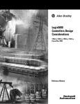
1
Bulletin 7712
OneGear 7.2 kV Motor Controller—Full-voltage,
Non-reversing
Publication Number 7712-UM001C-EN-P
Important User Information
Read this document and the documents listed in the Additional Resources section about installation, configuration, and
operation of this equipment before you install, configure, operate, or maintain this product. Users are required to
familiarize themselves with installation and wiring instructions in addition to requirements of all applicable codes, laws,
and standards.
Activities including installation, adjustments, putting into service, use, assembly, disassembly, and maintenance are required
to be carried out by suitably trained personnel in accordance with applicable code of practice.
If this equipment is used in a manner not specified by the manufacturer, the protection provided by the equipment may be
impaired.
In no event will Rockwell Automation, Inc. be responsible or liable for indirect or consequential damages resulting from the
use or application of this equipment.
The examples and diagrams in this manual are included solely for illustrative purposes. Because of the many variables and
requirements associated with any particular installation, Rockwell Automation, Inc. cannot assume responsibility or
liability for actual use based on the examples and diagrams.
No patent liability is assumed by Rockwell Automation, Inc. with respect to use of information, circuits, equipment, or
software described in this manual.
Reproduction of the contents of this manual, in whole or in part, without written permission of Rockwell Automation,
Inc., is prohibited.
Throughout this manual, when necessary, we use notes to make you aware of safety considerations.
WARNING: Identifies information about practices or circumstances that can cause an explosion in a hazardous environment,
which may lead to personal injury or death, property damage, or economic loss.
ATTENTION: Identifies information about practices or circumstances that can lead to personal injury or death, property
damage, or economic loss. Attentions help you identify a hazard, avoid a hazard, and recognize the consequence.
IMPORTANT
Identifies information that is critical for successful application and understanding of the product.
Labels may also be on or inside the equipment to provide specific precautions.
SHOCK HAZARD: Labels may be on or inside the equipment, for example, a drive or motor, to alert people that dangerous
voltage may be present.
BURN HAZARD: Labels may be on or inside the equipment, for example, a drive or motor, to alert people that surfaces may
reach dangerous temperatures.
ARC FLASH HAZARD: Labels may be on or inside the equipment, for example, a motor control center, to alert people to
potential Arc Flash. Arc Flash will cause severe injury or death. Wear proper Personal Protective Equipment (PPE). Follow ALL
Regulatory requirements for safe work practices and for Personal Protective Equipment (PPE).
Allen-Bradley, Rockwell Software, Rockwell Automation, and TechConnect are trademarks of Rockwell Automation, Inc.
Trademarks not belonging to Rockwell Automation are property of their respective companies.
Table of Contents
Preface
Introduction. . . . . . . . . . . . . . . . . . . . . . . . . . . . . . . . . . . . . . . . . . . . . . . . . . . . . . . 7
Who Should Use this Manual . . . . . . . . . . . . . . . . . . . . . . . . . . . . . . . . . . . . . . . 7
Service and Maintenance . . . . . . . . . . . . . . . . . . . . . . . . . . . . . . . . . . . . . . . . . . . 7
ArcShield Arc Flash Resistant Enclosure Features . . . . . . . . . . . . . . . . . . . . . 7
Controller Unit Identification . . . . . . . . . . . . . . . . . . . . . . . . . . . . . . . . . . . . . . 8
Additional Resources . . . . . . . . . . . . . . . . . . . . . . . . . . . . . . . . . . . . . . . . . . . . . . . 9
Chapter 1
General Information
Environmental Conditions . . . . . . . . . . . . . . . . . . . . . . . . . . . . . . . . . . . . . . . 11
Product Dimensions and Weights . . . . . . . . . . . . . . . . . . . . . . . . . . . . . . . . . 12
ArcShield Components Installation Requirements. . . . . . . . . . . . . . . . . . 13
Chapter 2
Safety Interlock and Accessibility
Requirements
Recommended Torque Values . . . . . . . . . . . . . . . . . . . . . . . . . . . . . . . . . . . .
Open the Enclosure Doors . . . . . . . . . . . . . . . . . . . . . . . . . . . . . . . . . . . . . . . .
Opening the Low Voltage Door . . . . . . . . . . . . . . . . . . . . . . . . . . . . . . .
Opening the Medium Voltage Door . . . . . . . . . . . . . . . . . . . . . . . . . . .
15
16
16
17
Chapter 3
Start-up Procedure
Contactor Inspection. . . . . . . . . . . . . . . . . . . . . . . . . . . . . . . . . . . . . . . . . . . . .
Preliminary Checks . . . . . . . . . . . . . . . . . . . . . . . . . . . . . . . . . . . . . . . . . . . . . .
Testing Contactor Operation . . . . . . . . . . . . . . . . . . . . . . . . . . . . . . . . . . . . .
Test Power Supply. . . . . . . . . . . . . . . . . . . . . . . . . . . . . . . . . . . . . . . . . . . .
Operating Position . . . . . . . . . . . . . . . . . . . . . . . . . . . . . . . . . . . . . . . . . . .
19
19
20
21
21
Chapter 4
Equipment Operation
Power Lockout Procedure . . . . . . . . . . . . . . . . . . . . . . . . . . . . . . . . . . . . . . . .
Open Contactor . . . . . . . . . . . . . . . . . . . . . . . . . . . . . . . . . . . . . . . . . . . . .
Power Down Low Voltage Section . . . . . . . . . . . . . . . . . . . . . . . . . . . . .
Selecting Power Source . . . . . . . . . . . . . . . . . . . . . . . . . . . . . . . . . . . . . . . . . . .
Connecting Test Power. . . . . . . . . . . . . . . . . . . . . . . . . . . . . . . . . . . . . . . . . . .
Racking Contactor Cart . . . . . . . . . . . . . . . . . . . . . . . . . . . . . . . . . . . . . . . . . .
Operation of Motor Controller . . . . . . . . . . . . . . . . . . . . . . . . . . . . . . . . . . .
Earthing Switch Operation. . . . . . . . . . . . . . . . . . . . . . . . . . . . . . . . . . . .
Earthing Switch Positioning Indicators. . . . . . . . . . . . . . . . . . . . . . . . .
Contactor Cart . . . . . . . . . . . . . . . . . . . . . . . . . . . . . . . . . . . . . . . . . . . . . . . . . .
Connect LV Plug. . . . . . . . . . . . . . . . . . . . . . . . . . . . . . . . . . . . . . . . . . . . .
Shutter Position Indicator . . . . . . . . . . . . . . . . . . . . . . . . . . . . . . . . . . . .
Rockwell Automation Publication 7712-UM001C-EN-P - June 2013
27
27
27
28
28
28
30
30
31
32
32
33
3
Table of Contents
Chapter 5
Maintenance
Required Tools. . . . . . . . . . . . . . . . . . . . . . . . . . . . . . . . . . . . . . . . . . . . . . . . . . .
Maintenance of Industrial Control Equipment . . . . . . . . . . . . . . . . . . . . .
Periodic Inspection . . . . . . . . . . . . . . . . . . . . . . . . . . . . . . . . . . . . . . . . . . .
Contamination . . . . . . . . . . . . . . . . . . . . . . . . . . . . . . . . . . . . . . . . . . . . . . .
Operating Mechanisms. . . . . . . . . . . . . . . . . . . . . . . . . . . . . . . . . . . . . . . .
Terminals . . . . . . . . . . . . . . . . . . . . . . . . . . . . . . . . . . . . . . . . . . . . . . . . . . . .
Coils. . . . . . . . . . . . . . . . . . . . . . . . . . . . . . . . . . . . . . . . . . . . . . . . . . . . . . . . .
Pilot Lights. . . . . . . . . . . . . . . . . . . . . . . . . . . . . . . . . . . . . . . . . . . . . . . . . . .
Annual Maintenance Requirements. . . . . . . . . . . . . . . . . . . . . . . . . . . . . . . .
Remove Contactor Cart . . . . . . . . . . . . . . . . . . . . . . . . . . . . . . . . . . . . . . . . . .
Remove and Replace Fuses . . . . . . . . . . . . . . . . . . . . . . . . . . . . . . . . . . . . . . . .
Contactor Cart Maintenance. . . . . . . . . . . . . . . . . . . . . . . . . . . . . . . . . . . . . .
Replace the Vacuum Bottles . . . . . . . . . . . . . . . . . . . . . . . . . . . . . . . . . . .
Calibrate the Overtravel and Contact Gap . . . . . . . . . . . . . . . . . . . . . .
Lubricate the Contactor Cart. . . . . . . . . . . . . . . . . . . . . . . . . . . . . . . . . .
Earthing Switch Maintenance . . . . . . . . . . . . . . . . . . . . . . . . . . . . . . . . . . . . .
Inspect and Lubricate Earthing Switch Mechanism . . . . . . . . . . . . . .
Ground Connection Inspection. . . . . . . . . . . . . . . . . . . . . . . . . . . . . . . .
Toggle Assembly Inspection . . . . . . . . . . . . . . . . . . . . . . . . . . . . . . . . . . .
Earthing Switch Auxiliary Maintenance . . . . . . . . . . . . . . . . . . . . . . . . . . . .
Auxiliary Contacts Replacement . . . . . . . . . . . . . . . . . . . . . . . . . . . . . . .
Auxiliary Contacts Adjustment . . . . . . . . . . . . . . . . . . . . . . . . . . . . . . . .
Earthing Switch Auxiliary Contacts Inspection. . . . . . . . . . . . . . . . . .
37
37
37
38
38
38
38
39
39
39
42
44
44
47
50
53
53
55
55
56
56
56
57
Appendix A
Spare Parts
Typical Bulletin 7712 Parts . . . . . . . . . . . . . . . . . . . . . . . . . . . . . . . . . . . . . . . 59
Appendix B
Certification Data
Test Summary . . . . . . . . . . . . . . . . . . . . . . . . . . . . . . . . . . . . . . . . . . . . . . . . . . . 61
High Voltage Controlgear Starter . . . . . . . . . . . . . . . . . . . . . . . . . . . . . . 61
Appendix C
Troubleshooting
Door Interlock Circumvention . . . . . . . . . . . . . . . . . . . . . . . . . . . . . . . . . . . . 63
Earthing Switch to Door . . . . . . . . . . . . . . . . . . . . . . . . . . . . . . . . . . . . . . 63
Door to Isolation Shutter. . . . . . . . . . . . . . . . . . . . . . . . . . . . . . . . . . . . . . 65
Appendix D
Mechanical Interlock for 7712 and
PowerFlex 7000 Drive
4
Keys. . . . . . . . . . . . . . . . . . . . . . . . . . . . . . . . . . . . . . . . . . . . . . . . . . . . . . . . . . . . .
KD and KE Keys . . . . . . . . . . . . . . . . . . . . . . . . . . . . . . . . . . . . . . . . . . . . .
KC Key . . . . . . . . . . . . . . . . . . . . . . . . . . . . . . . . . . . . . . . . . . . . . . . . . . . . .
KA and KB Keys . . . . . . . . . . . . . . . . . . . . . . . . . . . . . . . . . . . . . . . . . . . . .
KC Keys for doors . . . . . . . . . . . . . . . . . . . . . . . . . . . . . . . . . . . . . . . . . . . .
KD and KE Key for Output Cables Cabinet Door . . . . . . . . . . . . . .
Transfer Block . . . . . . . . . . . . . . . . . . . . . . . . . . . . . . . . . . . . . . . . . . . . . . .
Rockwell Automation Publication 7712-UM001C-EN-P - June 2013
69
69
69
69
69
69
70
Table of Contents
Connections. . . . . . . . . . . . . . . . . . . . . . . . . . . . . . . . . . . . . . . . . . . . . . . . . . . . .
Motor Connection from 7719. . . . . . . . . . . . . . . . . . . . . . . . . . . . . . . . .
Motor Connection from 7712. . . . . . . . . . . . . . . . . . . . . . . . . . . . . . . . .
Interlock Operation Sequence (One Motor). . . . . . . . . . . . . . . . . . . . . . . .
Initial Condition . . . . . . . . . . . . . . . . . . . . . . . . . . . . . . . . . . . . . . . . . . . . .
To Run Drive . . . . . . . . . . . . . . . . . . . . . . . . . . . . . . . . . . . . . . . . . . . . . . . .
To Run Bypass . . . . . . . . . . . . . . . . . . . . . . . . . . . . . . . . . . . . . . . . . . . . . . .
To open Drive for Service . . . . . . . . . . . . . . . . . . . . . . . . . . . . . . . . . . . . .
To open Output Cabinet . . . . . . . . . . . . . . . . . . . . . . . . . . . . . . . . . . . . .
Interlock Operation Sequence (Two Motors). . . . . . . . . . . . . . . . . . .
Rockwell Automation Publication 7712-UM001C-EN-P - June 2013
70
70
70
70
70
70
70
71
71
71
5
Table of Contents
Notes:
6
Rockwell Automation Publication 7712-UM001C-EN-P - June 2013
Preface
Introduction
This user manual provides installation instructions and maintenance procedures
for the Rockwell Automation Bulletin 7712 ArcShield™ arc flash resistant
enclosure, medium voltage controller. The Bulletin 7712 structure provides one
complete MV controller unit.
Who Should Use this
Manual
This manual is intended for qualified service personnel responsible for installing
and maintaining medium voltage controllers. You should have previous
experience with, and an understanding of, electrical terminology, procedures,
required troubleshooting equipment, equipment protection procedures and
methods, and safety precautions. See safety related practices contained in
publication NFPA 70E, Standard for Electrical Safety in the Work Place.
Service and Maintenance
For your convenience, Rockwell Automation Customer Support and
Maintenance (CSM), provides an efficient and convenient method of servicing
medium voltage products. Contact your local area support office to make
arrangements to have a qualified service representative come to your facility. A
complete listing of Area Support Offices may be obtained by calling your local
Rockwell Automation Distributor or Sales Office.
For Medium Voltage technical support on start-up or existing installations,
contact your Rockwell Automation representative. You can also call 1-519-7404790 for assistance Monday through Friday from 9:00 a.m. to 5:00 p.m. (Eastern
Time zone).
ArcShield Arc Flash
Resistant Enclosure
Features
Built to minimize exposure to electrical hazards, the OneGear 7.2 kV motor
controller includes an optional earthing switch and fully interlocked
compartment doors to isolate the power source when an apparatus cell door is
open. The controller features ArcShield arc flash-resistant enclosures, which
provide arc-flash protection in accordance with the IEC 62271-200 Annex A
standard.
The controller is designed, manufactured and tested to meet or exceed the
applicable requirements of the latest standards published by the following
organizations:
• IEC 60470: High-voltage Alternating Current Contactors and Contactor
Based Motor-Starters.
• IEC 62271-100: High-voltage Switchgear and Control Gear, Circuit
Breakers
• IEC 62271-1: High-voltage Switchgear and Control Gear, Common
Specifications
• IEC 62271-200: High-voltage Switchgear and Control Gear
• IEC 62271-102: High-voltage Switchgear and Control Gear,
Disconnectors and Earthing Switches
• European Directives for Safety and EMC
• RoHS
Note: It is the responsibility of the customer and/or installer to know and meet
all local codes, standards, and OSHA requirements.
Rockwell Automation Publication 7712-UM001C-EN-P - June 2013
7
Preface
Controller Unit
Identification
A nameplate is attached to the front door of the structure (see Figure 1). Refer to
the nameplate for information such as series number, section number, enclosure
type, unit ratings, and bus ratings.
Figure 1 - Typical Structure Nameplate
A nameplate is also found in the low voltage compartment (see Figure 2) with
specific unit and motor application information.
Figure 2 - Typical Unit/Motor Nameplate
Refer to these nameplates whenever you contact Rockwell Automation for
assistance. Be prepared to provide information such as series number, structure
series, unit series, diagram schematic, and catalog number.
8
Rockwell Automation Publication 7712-UM001C-EN-P - June 2013
Preface
Additional Resources
The following table lists publications that provide related information.
Resource
Description
OneGear 7.2 kV Motor Controller - Full-voltage,
Non-reversing and Incoming Line Unit - Technical
Data, 7712-TD001
Provides technical specifications and an
overview of the features and functions provided
by the controller and in-coming line unit.
OneGear SMC Flex Solid-State Motor Controller
(10…15 kV) Specification Guide, 7760-SR001
Provides a outline for the overall fabrication,
performance and functional requirements for a
medium voltage, reduced-voltage solid state
motor controller (RVSS) for use with induction
and brush type synchronous motors.
How to Successfully Apply Medium Voltage Soft
Starters, 1560E-WP023
Provides guidelines for selecting and applying
medium voltage starters.
SMC-Flex Controller with Pump Control,
150-WP003
Provides guidelines for applying the SMC-Flex
controller with pump control.
General Handling Procedures for Medium
Voltage Controllers Quick Start, MV-QS050
Provides basic information on installation site
preparation.
Medium Voltage Contactor 400A User Manual,
1502-UM052_-EN-P
Provides general guidelines for the application,
installation, and maintenance of 400A medium
voltage vacuum contactors.
You can view or download publications at http://www.rockwellautomation.com/
literature/. To order paper copies of technical documentation, contact your local
Rockwell Automation distributor or sales representative.
Rockwell Automation Publication 7712-UM001C-EN-P - June 2013
9
Preface
Notes:
10
Rockwell Automation Publication 7712-UM001C-EN-P - June 2013
Chapter
1
General Information
The chapter contains information essential for proper installation of the
OneGear™ 7.2 kV Bulletin 7712 medium voltage controller. Read all information
in this chapter before beginning the controller installation in Chapter 2.
Environmental Conditions
The standard controller is rated to operate in an ambient temperature range of
0...40 °C (32...104 °F) with a relative humidity of up to 95% (non condensing).
Higher ambient temperature conditions are supported with factory assistance.
The controller must be derated for ambient temperatures above
40 ºC (104 °F).
The equipment operates at altitudes from 0...1000 m (3300 ft) above sea level,
without de-rating. For applications above 1000 m (3300 ft), the maximum
current and Basic Impulse Levels (B.I.L.) of the controllers and incoming line
unit shall be de-rated and vacuum contactors/breakers will be compensated for
operation at the specified altitude.
Rockwell Automation products use materials that comply with Class 1: Industrial
Clean Air sulphur environments as defined in IEC Standard 60654-4 (Operating
Conditions for Industrial-Process Measurement and Control Equipment), and
G1 as defined in ISA-S71.04-1985 (Environmental Conditions for Process
Measurement and Control Systems: Airborne Contaminants).
Rockwell Automation Publication 7712-UM001C-EN-P - June 2013
11
Chapter 1
General Information
Product Dimensions and
Weights
Figure 3 - Controller Dimension Diagram
Table 1 - Approximate Dimensions and Weights
Width
Height(1)
Bulletin No.
Description
Depth
Weight
7712
250 A (single fuse)
FVNR Controller
350 mm
(13.78 in.)
2200 mm
(86.71 in.)
1100 mm
(43.31 in.)
489 kg
(1075 lb)
7712
330 A (double fuse)
FVNR Controller
350 mm
(13.78 in.)
2200 mm
(86.71 in.)
1100 mm
(43.31 in.)
504 kg
(1108 lb)
(1) The height dimension does not include the plenum (574 mm [22.60 in.]), which is removed for shipping and
installed by the customer. The total height of the unit including an installed plenum is 2674 mm (105.27 in.).
12
Rockwell Automation Publication 7712-UM001C-EN-P - June 2013
General Information
ArcShield Components
Installation Requirements
Chapter 1
The Bulletin 7712 ArcShield enclosure typically includes a pressure relief vent.
The pressure relief vent opens under arc flash conditions, allowing hazardous
flames and gases to exit the enclosure via plenum.
ATTENTION: The low voltage panel area is sealed to prevent flames and gases
from entering; however, suitable personal protective equipment (PPE) must be
used whenever working on live circuits.
ATTENTION: To ensure arc flash resistant integrity:
• The pressure relief vent must not be tampered with and must not be used as a
step.
• No alterations can be made to the ArcShield structure.
• All covers, plates, and hardware removed for installation or maintenance
purposes must be re-installed and properly secured. Failure to do so voids the
arc flash resistant integrity.
• Power cable entry points are to be treated as the boundary between a
hazardous location and sealed accordingly. Failure to do so voids the arc flash
resistant integrity.
• A plenum must be used to direct the arc flash energy to a suitable location.
Failure to do so voids the arc flash resistant integrity. See Publication 7712IN001_-EN-P for plenum installation instructions.
• All wiring between the low voltage panel and the power cell must be routed
through a suitable gland to ensure flames and gases are not transmitted into
this area (as fitted from factory).
• The medium voltage power cell doors must be properly secured, using the
handle mechanism (refer to instruction label on the power cell door and
page 16). Failure to do so voids the arc flash resistance integrity.
Rockwell Automation Publication 7712-UM001C-EN-P - June 2013
13
Chapter 1
General Information
Notes:
14
Rockwell Automation Publication 7712-UM001C-EN-P - June 2013
Chapter
2
Safety Interlock and Accessibility Requirements
ATTENTION: This procedure requires contact with medium voltage
components. To avoid shock hazards, complete the Power Lockout procedure on
page 27 before servicing the equipment. Verify with a hot stick or appropriate
voltage measuring device that all circuits are voltage free. Failure to do so may
result in severe burns, injury or death.
IMPORTANT
For general information on handling medium voltage controllers and
preparing the installation site, see publication MV-QS050_-EN-P.
ATTENTION: Use suitable personal protective equipment (PPE) per local codes
or regulations. Failure to do so may result in severe burns, injury, or death.
Recommended Torque
Values
When installing line and load cables or enclosure access panels, use the following
torque specifications.
Table 2 - Hardware Torque Specifications
Hardware Size
Tightening Torque Required
1/4 in. (M6)
6 ft•lb (8 N•m)
5/16 in. (M8)
12 ft•lb (16 N•m)
3/8 in. (M10)
20 ft•lb (22 N•m)
1/2 in. (M14)
48 ft•lb (65 N•m)
ATTENTION: Some components of this product incorporate Imperial hardware.
Rockwell Automation recommends the use of the appropriate tools to
successfully complete the maintenance procedures on these components. If you
cannot obtain such tools, contact your area Rockwell Automation sales office for
assistance.
Rockwell Automation Publication 7712-UM001C-EN-P - June 2013
15
Chapter 2
Safety Interlock and Accessibility Requirements
Open the Enclosure Doors
The controller contains separate low voltage and medium voltage compartments.
IMPORTANT
The medium voltage door is interlocked to the isolation shutter and/or the
earthing switch. The low voltage panel compartment and power cell are
separated by an isolation barrier.
Opening the Low Voltage Door
• Using an Allen key, turn the two 1/4-turn fasteners 90° clockwise and
swing the door to the left.
Close and secure the low voltage door in the reverse order of opening.
Figure 4 - Enclosure Compartments
ArecShield Plenum
Low Voltage Door
1/4-turn Fasteners
Medium Voltage Door
16
Rockwell Automation Publication 7712-UM001C-EN-P - June 2013
Safety Interlock and Accessibility Requirements
Chapter 2
Opening the Medium Voltage Door
ATTENTION: This procedure requires contact with medium voltage
components. To avoid shock hazards, complete the Power Lockout procedure on
page 27 before servicing the equipment. Verify with a hot stick or appropriate
voltage measuring device that all circuits are voltage free. Failure to do so may
result in severe burns, injury or death.
IMPORTANT
TIP
Failure to open the medium voltage door in the proper manner could damage
or jam the mechanical door interlocks. This may result in the mechanical
interlocks not operating as intended and may result in the door becoming
jammed in the closed position.
This procedure is contained on a label on the door of the controller for your
reference.
1. Electrically open the contactor by pressing the STOP button on the
controller or at the remote control location.
2. Move the contactor cart to the isolated position.
3. Ensure the earthing switch is closed (page 30).
4. Lift the release handle and swing the door to the left.
Close and secure the medium voltage door in the reverse order of opening.
Rockwell Automation Publication 7712-UM001C-EN-P - June 2013
17
Chapter 2
Safety Interlock and Accessibility Requirements
Figure 5 - Enclosure Compartments
ArecShield Plenum
Low Voltage Door
Controller STOP Button
Medium Voltage Door
Release Handle
Earthing Switch
18
Rockwell Automation Publication 7712-UM001C-EN-P - June 2013
Chapter
3
Start-up Procedure
Contactor Inspection
Preliminary Checks
See Chapter 2 in Medium Voltage Contactor 400A, Publication 1502-UM050_EN-P or 1502-UM052_-EN-P for information on pre-energization inspection,
vacuum bottle integrity test and insulation resistance test.
❏ Contactor current and voltage ratings are correct for the attached load
❏ Control voltage is correct
❏ Protective relay settings are correct
❏ Heater elements (if provided) in the overload relay are secure and
undamaged
❏ All equipment is correctly grounded
❏ External power and control connections match the electrical diagrams
❏ All hardware is correctly reinstalled and torqued to the correct
specification (see Recommended Torque Values on page 15)
❏ All barriers are replaced and in the correct position
❏ All fuses are the correct class, type, and rating
❏ Mechanical interlocks function properly
❏ Contactor cart functions properly
❏ Earthing switch functions properly
❏ Microprocessor-based protection relay is correctly programmed
❏ Enclosure interior is free from dirt, metal chips, loose hardware, and or
tools
Rockwell Automation Publication 7712-UM001C-EN-P - June 2013
19
Chapter 3
Start-up Procedure
Testing Contactor Operation
The contactor must be tested without any applied medium voltage. This should
be done for initial startup and after any maintenance is performed. This test
power supply should be within the IntelliVAC Vacuum Contactor Controller
specifications (1503-UM053_-EN-P). CPT on the cart is not energized when
the contactor is in the test/withdrawn position.
ATTENTION: Always perform the power lockout procedure before servicing
equipment. Failure to do so may result in severe burns, injury or death.
ATTENTION: The following procedure requires racking the contactor cart to its
test position. To avoid potential of shock hazards, disconnect and lockout
incoming power before proceeding. Failure to lockout incoming power will
result in a live bus cell. Once the shutter between power cell and bus cell is
open, it may cause severe burns, injury or death. Rockwell Automation does not
assume any responsibility for injuries to personnel who have not completed the
following safety procedure prior to servicing the equipment.
Connect an appropriate power cord to the power receptacle in the low voltage
compartment (Figure 6).
Figure 6 - Location of Control Switch and Auxiliary Power Receptacle
It is possible to open the MV door while the cart is in the test/withdrawn
position and the earthing switch is closed. The shutter behind the cart in the MV
compartment should be closed under this situation. This should be confirmed
after opening the MV door.
If the MV door cannot be opened smoothly, the shutter is not completely shut off
or the earthing switch is not completely closed.
20
Rockwell Automation Publication 7712-UM001C-EN-P - June 2013
Start-up Procedure
Chapter 3
When performing any actions during testing, the plug connected to the contactor
cart must be firmly connected. If the plug is not correctly connected, the
contactor cart will not operate reliably.
Test Power Supply
ATTENTION: Use suitable personal protective equipment (PPE) per local codes
or regulations. Failure to do so may result in severe burns, injury or death.
Verify that the contactor cart has been racked to its test/withdrawn position.
1. Open the low voltage door.
2. Plug the appropriate power supply into the test power receptacle.
3. Move the control switch to test position so that the control circuit is
powered by the test power supply.
4. After the tests, disengage the contactor and move the control switch to the
normal position. Disconnect the external power supply.
5. Complete the Power Lockout procedure.
IMPORTANT
It is not possible to use any test power supply after the contactor cart has been
racked out of the test position. A set of auxiliary switches on the contactor cart
prevent the MV parts from being back fed by any low voltage power supply
through the CPT.
Operating Position
ATTENTION: Use suitable personal protective equipment (PPE) per local codes
or regulations. Failure to do so may result in severe burns, injury, or death.
ATTENTION: The following procedure applies medium voltage to the contactor
cart and the load terminals. To avoid shock hazards, the MV and LV doors must
be closed. Failure to do so may result in severe burns, injury, or death. Rockwell
Automation assumes no responsibility for injuries to personnel who do not
follow the safety procedures prior to servicing or operating the equipment.
Operating position is designed only for performing normal functions of this
equipment. Any operation on the contactor will affect the MV status on the load
side.
When the contactor cart is racked to operating position, the MV parts on the line
side, including CPT is default has been chosen, would be connected to the line
side buses of this equipment so that they would be energized by MV. As a result
of energizing CPT, control power would be applied to the LV circuit connected
to it.
Rockwell Automation Publication 7712-UM001C-EN-P - June 2013
21
Chapter 3
Start-up Procedure
The cart must be in the operating position and the earthing switch must be open.
It is not possible to operate the contactor by the test power supply while the
contactor cart is in operating position. To perform any operation with the
contactor engaged, either MV should be applied on the line side bus of this
equipment so that the MV energized on-cart CPT would power up the control
circuits, or a customer supplied power supply should have been wired to the LV
panel as designed.
Test the Contactor
Contactor must be in the withdrawn/test position
1. Connect the appropriate external power supply (120V or 230V AC) to the
test receptacle in the control panel. Turn the selector switch to the TEST
position.
ATTENTION: Some control circuit configurations may require control jumpers to
let the contactor close during the test procedure. Do not jumper any contactor
cart position auxiliary contacts. Using jumpers for these contacts can result in
equipment damage or injury to personnel.
2. Electrically operate the contactor several times. Inspect the armature plate
to verify that it fully contacts the magnetic cores.
Contactor should close when close command is given. IntelliVAC module
will detect and display fault if a problem exists.
3. Turn the selector switch to the OFF position and disconnect the external
power supply.
Inspect the area around the magnetic cores of the vacuum contactor and remove
any metal filings, if present. This type of debris is attracted to the coil once it is
energized and could prevent the contactor from closing properly.
22
Rockwell Automation Publication 7712-UM001C-EN-P - June 2013
Start-up Procedure
Chapter 3
Figure 7 - Typical Wiring Diagram: Electrically Held Vacuum Contactor (with IntelliVAC Control) )
Rockwell Automation Publication 7712-UM001C-EN-P - June 2013
23
Chapter 3
24
Start-up Procedure
Rockwell Automation Publication 7712-UM001C-EN-P - June 2013
Start-up Procedure
Rockwell Automation Publication 7712-UM001C-EN-P - June 2013
Chapter 3
25
Chapter 3
26
Start-up Procedure
Rockwell Automation Publication 7712-UM001C-EN-P - June 2013
Chapter
4
Equipment Operation
Power Lockout Procedure
The power lockout procedure removes all power from user-accessible areas.
ATTENTION: Use suitable personal protective equipment (PPE) per local codes
or regulations. Failure to do so may result in severe burns, injury, or death.
ATTENTION: Always perform the power lockout procedure before servicing
equipment. Failure to do so may result in severe burns, injury, or death.
Open Contactor
The contactor can operate (open or closed) only when the contactor cart is in the
operating or test position.
1. Remove the close command applied on IntelliVAC.
• If the system is running at Local mode, push the Open button on the
low voltage control panel.
• If the system is running at System mode, apply the Open command
from a higher level controller.
2. Open low voltage door to check the contactor status LED of IntelliVAC;
it must be off.
Power Down Low Voltage Section
Besides either customer supplied LV power or defaulted CPT mounted on the
contactor cart, the Low Voltage Section can also be powered by a temporary LV
test power supply.
1. Turn the selection switch to Off.
2. Unplug the temporary test power supply.
3. Disconnect any customer supplied power supply using standard lockout/
tagout procedures.
Rockwell Automation Publication 7712-UM001C-EN-P - June 2013
27
Chapter 4
Equipment Operation
Selecting Power Source
Connecting Test Power
The selector switch on the Control Switch assembly can either be turned from
Normal-Off-Test.
Test
To test the starter without medium voltage present.
Normal
To operate the starter in normal position.
Off
To prevent the starter from operation.
1. Disconnect and lock out all feeder power supplies to the starter.
2. Rack the contactor cart to the test/withdrawn position.
3. If the unit is equipped with power factor correction capacitors, stored
energy must be dissipated before entering the power cell or dissipate the
power using the following procedure.
a. Verify the contactor cart is in test/withdrawn position.
b. Open the LV door.
c. Plug the appropriate power supply (120 or 230V) into the auxiliary
power receptacle on the control panel.
d. Move the control switch to the Test position.
e. Electrically operate the contactor by pushing the Start button on the
unit or at a remote location.
f. Disengage the contactor and turn the control switch to the Normal
position. Disconnect the external power supply.
g. Complete the Power Lockout procedure.
4. Use a 120V power cord and plug into the 120V plug on the Control
Switch Assembly (see Figure 6 on page 20) to test the starter without
Medium Voltage being present in the starter.
Racking Contactor Cart
To change the condition of the contactor cart,
• the main cabinet door must be closed
• earthing switch must be open
• the contactor status must read OPEN.
ATTENTION: The contactor cart must be racked out using tools supplied by
Rockwell Automation only. Failure to do so can cause damage to equipment,
personal injury, or death.
28
Rockwell Automation Publication 7712-UM001C-EN-P - June 2013
Equipment Operation
Chapter 4
1. Open the tool access flap on the door using a flat screw driver (Figure 8).
Figure 8 - Open Tool Access Flap
2. Rotate the cover counterclockwise exposing the square end of the cart
screw.
3. Insert the speed wrench and push toward rear of cabinet.
The wrench must be pushed toward rear of cabinet to unlock the cart
raking screw. The pressure must be maintained for the entire cart
insertion/withdraw operation.
4. If cart is in test/withdrawn position, rotate the speed wrench clockwise to
insert the cart (Figure 9). From test to service position requires
11 complete rotations (a mechanism stops the screw rotation after
11 turns). The last turns require more torque to overcome the cart
engagement resistance.
Figure 9 - Position Speed Wrench
Rockwell Automation Publication 7712-UM001C-EN-P - June 2013
29
Chapter 4
Equipment Operation
5. Withdraw speed wrench tool.
IMPORTANT
Operation of Motor
Controller
The tool must be withdrawn from the mechanism without any rotation. This
ensures the locking plate in the front of the cart will slide forward and lock the
end of the racking screw locking in the same time the cart position. The tool
access flap must cover the opening after the speed wrench is redrawn.
Earthing Switch Operation
IMPORTANT
Before opening the earthing switch, ensure:
• the contactor cart is in the withdrawn/test position; and,
• the door is closed and latched.
Open Earthing Switch
1. Insert the earthing switch tool at the end of the earthing switch shaft
(Figure 10).
Figure 10 - Open Earthing Switch
Earthing Switch
Shaft
Earthing
Switch
Tool
2. Rotate the earthing switch tool approximately 65° clockwise until the
switch is completely open.
Close Earthing Switch
IMPORTANT
30
Before closing the earthing switch, ensure:
• the contactor cart is in test/withdrawn position (if the cart is in the
operating position, the earthing switch will not close); and,
• the door is closed and latched.
Rockwell Automation Publication 7712-UM001C-EN-P - June 2013
Equipment Operation
Chapter 4
1. Insert the earthing switch tool at the end of the earthing switch shaft
(Figure 11).
Figure 11 - Close Earthing Switch
Earthing Switch
Shaft
Earthing
Switch
Tool
2. Rotate the earthing switch tool approximately 60° counterclockwise until
the switch is completely closed.
Earthing Switch Positioning Indicators
An arrow at the end of the earthing switch shaft indicates the state of the switch.
Depending on the position of the earthing switch, the arrow points to the
corresponding decal located on the door.
Earthing switch OPEN
Unearthed
Earthing switch CLOSED
Earthed
Open/Closed Position Indicator Decal
In the closed position (Figure 12), the arrow points toward “I” (red background).
Figure 12 - Switch indicator - Off
Closed
position
Rockwell Automation Publication 7712-UM001C-EN-P - June 2013
31
Chapter 4
Equipment Operation
In the open position (Figure 13), the arrow points toward “O” (green
background).
Figure 13 - Switch indicator - On
Open
position
Contactor Cart
IMPORTANT
LV must be connected for unit functionality. The LV plug should only be
disconnected when the contactor cart is removed from the unit for service.
Connect LV Plug
To connect or disconnect the LV Plug, the contactor cart must be in the test/
withdrawn position. The LV Plug and cable is attached on the cabinet door and is
connected to the equipment in the LV cabinet on the top.
1. Orient the LV plug aligning the guide pins on the cart with the openings in
the plug.
2. Push down the plug and secure the connection with the locking arm
mounted on the cart (Figure 14).
32
Rockwell Automation Publication 7712-UM001C-EN-P - June 2013
Equipment Operation
Chapter 4
Figure 14 - Connect LV Plug
Shutter Position Indicator
An indicator in the door (Figure 15) changes color (red or green) depending on
the shutter door position.
Green
The shutter door is closed (Figure 17); the cart is
completely redrawn in the test position.
Red
The shutter door is open (Figure 18); the indicator will
change immediately after moving the cart from test/
withdrawn position to the service position.
The color of the indicator will change to red even if the shutter door is partially
open.
Figure 15 - Shutter position Indicator
Indicator
Close position (Green)
Open position (Red)
Viewing Window
Rockwell Automation Publication 7712-UM001C-EN-P - June 2013
33
Chapter 4
Equipment Operation
TIP
If the shutter door is partially or fully open, an interlock prevents the MV door
from opening.
A viewing window (Figure 16) shows the position of the contactor cart.
Figure 16 - Viewing Window
Viewing Window
Indicator
Figure 17 - Shutter closed
34
Rockwell Automation Publication 7712-UM001C-EN-P - June 2013
Equipment Operation
Chapter 4
Figure 18 - Shutter open
Rockwell Automation Publication 7712-UM001C-EN-P - June 2013
35
Chapter 4
Equipment Operation
Notes:
36
Rockwell Automation Publication 7712-UM001C-EN-P - June 2013
Chapter
5
Maintenance
Required Tools
Maintenance of Industrial
Control Equipment
•
•
•
•
•
•
•
•
•
•
•
•
Torque wrench: 0...48 lb•ft (0...65 N•m)
Sockets: 3/8 in., 7/16 in., 9/16 in.
Ratchet handle and extension
Wrenches: 7/16 in., 1/2 in., 9/16 in.
Feeler gauges: 0.050 in. (1.3 mm), 0.080 in. (2 mm), 0.020 in. (0.5 mm)
Flat-blade screwdriver
Nyogel 759G Lubricant (Allen-Bradley part no. 80158-357-51)
MV Door Key
Allen Key
Speed Wrench
Cart-latch key
Earthing Switch operating tool
ATTENTION: Servicing energized Industrial Control Equipment can be
hazardous. Severe injury or death can result from electrical shock, bump, or
unintended actuation of controlled equipment. Recommended practice is to
disconnect and lockout control equipment from power sources, and release
stored energy, if present. Refer to National Fire Protection Association Standard
No. NFPA70E, Part II and (as applicable) OSHA rules for Control of Hazardous
Energy Sources (Lockout/Tagout) and OSHA Electrical Safety Related Work
Practices for safety related work practices, including procedural requirements
for lockout-tagout, and appropriate work practices, personnel qualifications
and training requirements where it is not feasible to de-energize and lockout or
tagout electric circuits and equipment before working on or near exposed
circuit parts.
Periodic Inspection
Industrial control equipment should be inspected periodically. Inspection
intervals should be based on environmental and operating conditions and
adjusted as indicated by experience. An initial inspection within 3...4 months
after installation is suggested. See National Electrical Manufacturers Association
NEMA) Standard No. ICS 1.3, Preventive Maintenance of Industrial Control
and Systems Equipment, for general guidelines for setting-up a periodic
maintenance program. Some specific guidelines for Rockwell Automation
products are listed below.
Rockwell Automation Publication 7712-UM001C-EN-P - June 2013
37
Chapter 5
Maintenance
Contamination
If inspection reveals that dust, dirt, moisture or other contamination has reached
the control equipment, the cause must be eliminated. This could indicate an
incorrectly selected or ineffective enclosure, unsealed enclosure openings
(conduit or other) or incorrect operating procedures. Replace any improperly
selected enclosure with one that is suitable for the environmental conditions refer to NEMA Standard No. 250, Enclosures for Electrical Equipment for
enclosure type descriptions and test criteria. Replace any damaged or cracked
elastomer seals and repair or replace any other damaged or malfunctioning parts
(e.g., hinges, fasteners, etc.). Dirty, wet or contaminated control devices must be
replaced unless they can be cleaned effectively by vacuuming or wiping.
Compressed air is not recommended for cleaning because it may displace dirt,
dust, or debris into other parts or equipment, or damage delicate parts.
Operating Mechanisms
Check for proper functioning and freedom from sticking or binding. Replace any
broken, deformed or badly wont parts or assemblies according to individual
product renewal parts lists. Check for and retighten securely any loose fasteners.
Lubricate if specified in individual product instructions. Note: Allen-Bradley
magnetic starters, contactors and relays are designed to operate without
lubrication-do not lubricate these devices because oil or grease on the pole faces
(mating surfaces) of the operating magnet may cause the device to stick in the
“ON” mode. Some parts of other devices are factory lubricated-if lubrication
during use or maintenance of these devices is needed, it will be specified in their
individual instructions. if in doubt, consult your nearest Allen-Bradley Sales
Office for information.
Terminals
Loose connections in power circuits can cause overheating that can lead to
equipment malfunction or failure. Loose connections in control circuits can
cause control malfunctions. Loose bonding or grounding connections can
Increase hazards of electrical shock and contribute to electromagnetic
interference (EMI). Check the tightness of all terminals and bus bar connections
and tighten securely any loose connections. Replace any parts or wiring damaged
by overheating, and any broken wires or bonding straps.
Coils
If a coil exhibits evidence of overheating (cracked, melted or burned insulation),
it must be replaced. In that event, check for and correct overvoltage or
undervoltage conditions, which can cause coil failure. Be sure to dean any
residues of melted coil insulation from other parts of the device or replace such
parts.
38
Rockwell Automation Publication 7712-UM001C-EN-P - June 2013
Maintenance
Chapter 5
Pilot Lights
Replace any burned out lamps or damaged lenses. Photoelectric Switches-The
lenses of photoelectric switches require periodic cleaning with a soft dry cloth.
Reflective devices used in conjunction with photoelectric switches also require
periodic cleaning. Do not use solvents or cleaning agents on the lenses or
reflectors. Replace any damaged lenses and reflectors.
Annual Maintenance
Requirements
Task
Page
Remove Contactor Cart
39
Remove and Replace Fuses
42
Contactor Cart Maintenance
44
Replace the Vacuum Bottles
44
Calibrate the Overtravel and Contact Gap
47
Lubricate the Contactor Cart
50
Earthing Switch Maintenance
Remove Contactor Cart
53
Inspect and Lubricate Earthing Switch Mechanism
53
Ground Connection Inspection
55
Toggle Assembly Inspection
55
Earthing Switch Auxiliary Maintenance
56
Auxiliary Contacts Replacement
56
Auxiliary Contacts Adjustment
56
Earthing Switch Auxiliary Contacts Inspection
57
To replace the fuses, the contactor cart must be removed from the cabinet. Below
the contactor cart door are two pin holes that receive the pins on the service cart.
1. Align the service cart with the enclosure, ensuring the contactor cart
platform is the same elevation as the service cart rails.
2. Move the service cart to the cabinet, and insert the cart pins into the
enclosure (Figure 19).
ATTENTION: A locking key on the front of the cart must be
engaged to ensure the service cart does not roll when removing
the contactor cart.
Rockwell Automation Publication 7712-UM001C-EN-P - June 2013
39
Chapter 5
Maintenance
Figure 19 - Securing Service Cart to the front of the Cabinet
3. Insert cart latch key into the cart latch disengagement and turn the key
approximately a quarter turn clockwise (Figure 20).
Ensure latch is disengaged from the rail.
Figure 20 - Contactor Cart Latch
Disengage cart latch
40
Rockwell Automation Publication 7712-UM001C-EN-P - June 2013
Maintenance
Chapter 5
4. Keeping the key engaged, grasp the handle (Figure 21) and remove the
contactor cart from the enclosure onto the service cart.
Figure 21 - Contactor Cart Removal Handle
5. Once the contactor cart is extracted from the cabinet, secure the cart using
the latch and the service cart wheels to prevent movement.
Figure 22 - Contactor Cart removed from enclosure
Rockwell Automation Publication 7712-UM001C-EN-P - June 2013
41
Chapter 5
Maintenance
Remove and Replace Fuses
1. Unscrew eight M8 bolts to remove the red Glastic cover (Figure 23).
Figure 23 - Remove Glastic cover
42
Rockwell Automation Publication 7712-UM001C-EN-P - June 2013
Maintenance
Chapter 5
2. Replace each fuse by removing four M10 nuts (Figure 24).
Figure 24 - Fuse Removal
3. Replace the M10 nuts and reattach the Glastic cover using the M8 bolts.
Rockwell Automation Publication 7712-UM001C-EN-P - June 2013
43
Chapter 5
Maintenance
Contactor Cart Maintenance
Replace the Vacuum Bottles
Under normal conditions, vacuum bottles will last at least 1,000,000 operations;
however, all three bottles must be replaced if any wear indicator line (Figure 25)
reaches the bearing (regardless of the number of operations).
Figure 25 - Vacuum bottle wear indicator
Vacuum Bottle
Wear indicator line
on operating shaft
To access the vacuum bottles, the glastic cover must be removed. See page 42.
1. Unscrew eleven M8 bolts to remove the fuse mounting mold (Figure 26).
Figure 26 - Remove Fuse Mounting Mold
44
Rockwell Automation Publication 7712-UM001C-EN-P - June 2013
Maintenance
TIP
Chapter 5
Before removing the vacuum bottles, mark the installed bottles clearly to
avoid confusing them with the replacement vacuum bottles.
2. Remove the lower terminal connections at the rear of the contactor
(Figure 27).
Figure 27 - Remove lower terminal connections
3. Remove the load terminal retaining bolt at the rear of the contactor, and
the vacuum bottle mounting bolt at the top of the contactor (Figure 28).
Figure 28 - Mounting and Retaining bolt removal
Rockwell Automation Publication 7712-UM001C-EN-P - June 2013
45
Chapter 5
Maintenance
4. Loosen the load terminal nut on one bottle assembly, tilt the bottle
forward (out of the contactor) and unscrew it from the insulator stud
(Figure 29). Remove bottle braces, and repeat for the two remaining
bottles.
The load terminals, insulators and overtravel spring assemblies remain in
the Contactor.
Figure 29 - Remove Vacuum Bottles
5. Install a new bottle by tilting an insulator forward and threading the bottle
onto the stud. The threads must align to prevent cross-threading. Thread
the bottle down, leaving a gap of approximately 4.82 mm ± 0.25 mm
(0.190 in. ± 0.01 in.) between the top of the bottle and the bottom surface
of the line terminal (Figure 30). Use an appropriate measuring tool to set
the gap. This gap is precisely calibrated later in this section.
The wear indicator line on the bottom of the bottle's movable shaft must
be visible from the front of the contactor. Repeat this step for the
remaining two bottles.
46
Rockwell Automation Publication 7712-UM001C-EN-P - June 2013
Maintenance
Chapter 5
Figure 30 - Establishing Contact Gap
0.190 in. [4.82 mm]
Vacuum Bottles
Insulator
6. Install the load terminal retaining bolts at the rear of the contactor.
Leave the load terminal nuts loose for fine adjustment of the overtravel and
contact gap.
7. Install the vacuum bottle mounting bolts at the top of the contactor
(reverse of step 3). Ensure the threads align to prevent cross-threading.
Hold the bottle to prevent it from turning while torquing the vacuum
bottle mounting bolts.
Calibrate the Overtravel and Contact Gap
1. Close the contactor by using the TEST control circuit in the starter. Insert
a feeler gauge of 0.065 in. (1.65 mm) into the overtravel gap of a bottle
assembly (Figure 31).
2. Rotate the insulator until the gap is correct. Repeat for the two remaining
bottles.
IMPORTANT
This establishes synchronization between the three vacuum bottles.
Rockwell Automation Publication 7712-UM001C-EN-P - June 2013
47
Chapter 5
Maintenance
Figure 31 - Establishing Overtravel
Overtravel Gap
0.065 in. [1.65 mm]
3. Measure dimension A1 for all three bottles with the contactor still
energized (Figure 32).
4. De-energize (drop out) the contactor and measure dimension A2 for all
three bottles.
The contact gap is the difference of A2 minus A1. Record the gap for all
three bottles.
48
Rockwell Automation Publication 7712-UM001C-EN-P - June 2013
Maintenance
Chapter 5
Figure 32 - Measuring Contact Gap
A1
IMPORTANT
A2
The contact gaps must be synchronized within 0.02 in. (0.5 mm). If the gaps
are not synchronized, rotate the insulators as required. The overtravel must
remain at least 0.065 in. (1.65 mm) on each bottle.
5. Tighten the load terminal nut on each bottle assembly.
Apply wrenches to the load terminal nut and to the flattened section of the
movable bottle shaft to prevent damage to the bellows.
6. Tighten the load terminal nut while holding the bottle shaft steady.
Do not turn the insulator as this changes the gap.
7. The final contact gap for all three bottles must be between
0.180...0.200 in. (4.57...5.08 mm). If this is the case, the replacement
procedure is complete.
If further adjustment is required, all three gaps can be adjusted
simultaneously by loosening the stop bracket bolts and adjusting the
height of the gap adjustment screw at the rear of the contactor (Figure 33).
To adjust the height of the screw, first loosen the locking nut.
8. When the gap is correct, tighten the gap adjustment screw locking nut.
9. Position the stop bracket lightly against the armature plate and tighten the
bolts securing the stop in position.
Ensure that the actuator plate contacts the gap adjustment screw and the
armature plate contacts the stop bracket (Figure 33).
Rockwell Automation Publication 7712-UM001C-EN-P - June 2013
49
Chapter 5
Maintenance
Figure 33 - Contact Gap Adjustment
Gap Adjustment Screw
Gap Adjustment Screw
Locking Nut
Stop Bracket Bolts
Stop Bracket
10. Reconnect the lower terminal connections at the rear of the contactor, and
replace eleven M8 bolts to install the fuse mounting mold.
Lubricate the Contactor Cart
1. Grease the contactor interlock rod using Aeroshell No.7 (Figure 34).
Figure 34 - Lubricate interlock rod
50
Rockwell Automation Publication 7712-UM001C-EN-P - June 2013
Maintenance
Chapter 5
2. Grease the front assembly guide rod on both side of the cart using
Aeroshell No.7 (Figure 35).
Figure 35 - Lubricate guide rod
3. Grease door to cart interlock sliding bracket Using Aeroshell No.7
(Figure 36).
Figure 36 - Lubricate the sliding bracket
Rockwell Automation Publication 7712-UM001C-EN-P - June 2013
51
Chapter 5
Maintenance
4. Grease the tulip fingers Using Nye lubricant (Nyogel 759G) (Figure 37).
Figure 37 - Lubricate the Tulip Fingers
52
Rockwell Automation Publication 7712-UM001C-EN-P - June 2013
Maintenance
Earthing Switch
Maintenance
Chapter 5
Inspect and Lubricate Earthing Switch Mechanism
1. Inspect the lubrication between the ground stab and the earthing switch
blades.
2. Apply Nye lubricant (Nyogel 759G) to the ground stab (Figure 38) as
needed.
Figure 38 - Lubricate Earthing Switch Mechanism
Rockwell Automation Publication 7712-UM001C-EN-P - June 2013
53
Chapter 5
Maintenance
3. Grease (Aeroshell No. 7) the main shaft, mating surface of cam and gear,
mating surface of shaft and gear housing (Figure 39).
Figure 39 - Lubricate Earthing Switch Mechanism
54
Rockwell Automation Publication 7712-UM001C-EN-P - June 2013
Maintenance
Chapter 5
Ground Connection Inspection
1. Inspect the torque seal for the ground connection.
2. If seal is broken, apply 11 lb•ft (14.5 N•m) to secure and apply torque seal.
Figure 40 - Ground Connection Inspection
Toggle Assembly Inspection
1. Inspect the torque seal of the shoulder bolt for the toggle assembly.
2. If seal is broken, apply 4.4 lb•ft (6.0 N•m) to secure the shoulder bolt and
apply torque seal.
Figure 41 - Toggle Assembly Inspection
Rockwell Automation Publication 7712-UM001C-EN-P - June 2013
55
Chapter 5
Maintenance
Earthing Switch Auxiliary
Maintenance
Auxiliary Contacts Replacement
1. Remove all the wire connected to the auxiliary and mark each wire for
rewiring.
2. Remove the auxiliary mounting hardware (M3.5 hex nut, washer, and
cheese head screw).
3. Replace the existing auxiliary.
4. Rewire the terminals with correct wire and secure the auxiliary with the
mounting hardware.
Figure 42 - Auxiliary Contacts Replacement
Auxiliary Contacts Adjustment
The auxiliary is mounted to a slotted L-bracket using a M3.5 cheese head screw,
washer, and nut. The L-bracket with the auxiliary is mounted to the base of the
earthing switch using two M6 taptie. The switch must be positioned so the roller
of the auxiliary sits on top of the actuator hump.
Horizontal Adjustment
1. Loosen the auxiliary mounting hardware (two M3.5 hex nuts).
2. Adjust the auxiliary as required.
3. Secure the adjusted position of auxiliary by tightening the nut.
56
Rockwell Automation Publication 7712-UM001C-EN-P - June 2013
Maintenance
Chapter 5
Vertical Adjustment
1. Loosen the two tapties that mount the L-bracket to the base.
2. Move the L-bracket up and down as required.
3. Secure the adjusted position of auxiliary by tightening the two M6 taptie.
Figure 43 - Auxiliary Contacts Adjustment
Earthing Switch Auxiliary Contacts Inspection
Operation of electrical auxiliaries must be validated on a yearly basis.
IMPORTANT
Auxiliaries must be tested electrically with control power off.
Refer to the unit electrical drawing to determine the test locations on the
terminals located in the low voltage compartment.
Rockwell Automation Publication 7712-UM001C-EN-P - June 2013
57
Chapter 5
Maintenance
Notes:
58
Rockwell Automation Publication 7712-UM001C-EN-P - June 2013
Appendix
A
Spare Parts
Typical Bulletin 7712 Parts
Contact your local Rockwell Automation office to ensure that the following part
numbers are available.
Part Number
Description
Recommended
Stocking Quantity
1503VC-BMC5
Intellivac
1
80174-902-14-R
Intellivac internal fuse
1
Power Fuses
ENG Data
3
Primary fuses (CPT)
ENG Data
2
Contactor cart
ENG Data
1
80158-357-51
Nyogel 759G lubricant
1
80026-795-01
Contactor cart auxiliary contact
2
PN-125239
Earthing switch auxiliary contact
2
81057-496-52
Vacuum bottles (set of 3)
1
80026-230-01
Main contactor coils (2 required)
2
28325-042-01
Coil retaining ring
2
80153-567-01
Return spring
2
80153-552-02
Armature plate
1
80158-743-52
Auxiliary assembly
1
Contactor Parts
Rockwell Automation Publication 7712-UM001C-EN-P - June 2013
59
Appendix A
Spare Parts
Notes:
60
Rockwell Automation Publication 7712-UM001C-EN-P - June 2013
Appendix
B
Certification Data
Test Summary
High Voltage Controlgear Starter
Model 7712 Rating
Rated Voltage
7.2 kV
Rated lightning impulse withstand voltage
60 kV
Rated power-frequency withstand voltage
20 kV
Rated frequency
50/60 Hz
Rated normal current busbar
2000 A
Rated normal current
330 A
Rated short-time withstand current
50 kA rms
Rated peak withstand current
125 kA
Rated duration of short circuit bus bar
3s
Rated duration of short circuit vertical bus bar
0.3 s 1 CO
Arc Flash classification
IEC 31.5 kA/0.1s, AFLR
The Controlgear starter unit provided with vacuum contactor, model 7712, and
components have been tested per following applicable standards. See Table 3 for
test parameters and test reports.
• IEC 60470, High-voltage alternating current contactors and contactorbased motor-starters.
• IEC 62271-1, High-voltage switchgear and control gear - Part 1: Common
specifications.
• IEC 62271-102, High-voltage switchgear and control gear - Part 102:
Alternating current disconnectors and earthing switches.
• IEC 62271-200, High-voltage switchgear and control gear - Part 200: AC
metal-enclosed switchgear and control gear for rated voltages above 1 kV
and up to and including 52 kV.
Rockwell Automation Publication 7712-UM001C-EN-P - June 2013
61
Appendix B
Certification Data
Table 3 - Test reports verifying ratings assigned by the manufacturer:
Performances
Test According to Standard/Clause
Test Reports
Number
Issued By
Dielectric Tests
Power frequency withstand 20 kV/1 min
20969-B-26
07/06/2011
Impulse 15± 60 kV/1.2/50 μs
20969-B-26
07/06/2011
Powertech
ER-059-2012
Rockwell Automation
LV control 2 kV/1 min
IEC 82271-1/6.2.10
ER-004-2012
Rockwell Automation
Measurement of Circuit Resistance
IEC 60470/6.4, IEC 62271-1/6.4
20969-B-26, 07/06/2011
Powertech
Temperature Rise Test
7712 Starter 250 A
IEC 60470/6.5, IEC62271-1/6.5, Table 3
11071-C, 03/29 - 31/2011
KEMA
Verification of operating limits +10%,
-15% LV control
IEC 6470/6.101.1
20969-A-26
07/06/2011
Powertech
IEC 60470/6.6
IEC 6227101/6.6.2
IEC 562271-200/
11069-B 03/28/2011
KEMA
20158-1 08/16-18/2010
Powertech
20969-D-26 07/08/2011
Powertech
IEC 62271-102/6.101
IEC 62271-200/6.6b
EP-2485R
Rockwell Automation (HCL)
Earthswitch and starter 50CO
IEC 6470/6.101.2
ER-069-2012
Rockwell Automation
Interlock 25CO
IEC 6470/6.101.3
ER-069-2012
Rockwell Automation
Earthswitch Class M1 2000 CO
IEC 62271-102/4.106, 6.102
ER-110-2011
Rockwell Automation
IEC 6470/6.102.7
20969-B-26
07/06/2011
Powertech
Powertech
Short-time and peak withstand tests
Main bus 50 kA/3 s
Ground bus 60 kA/3 s
Vertical bus 50 kA/0.3 s
Earthing switch 31.5 kA/
Mechanical Operation Tests
Overload Current Tests
6 kA/1 s
2.4 kA/30 s
Rated making and breaking capacity tests AC4
Fused starter making 4 kA/100C Table 10,
12 kV TRV
IEC 62271-1/6.102.4
20969-A-26
07/06/2011
Fused starter breaking 3.2k25O, 80 A/25O,
Table 10, 12kV TRV
IEC 62271-1/6.102.5
20969-A-26
07/06/2011
Starter Make/Break 1CO at 6.1 kA
IEC60470/6.104
20969-E-26
07/08/2011
Powertech
Earthing Switch Making
5 x C @ 31.5 kA Peak
IEC 60265, 6.107.1
EP-2485R
Rockwell Automation (HCL)
Type A -40kArms 1O (fused)
IEC60470/6.106.3.1
Powertech
Type B 40kArms 1CO (fused)
IEC60470/6.106.3.2
20969-C-26
07/07/2011
Type C 5.1kArms 3CO (unfused)
IEC60470/6.106.3.3
ER-070-2012
Rockwell Automation
ER-070-2012
Rockwell Automation
20158-2, 08/16-18/2010
Powertech
Short-circuit making and breaking tests
SCPD Coordination
Degree of Protection
External surface IP4X
Internal barriers IP2X
IEC 60470/5/13
IEC 62271-1/5.13
Arc Tests
7712 Starter 31.5 kA/0.5 s line side
62
IEC 62271-200/ Annex A, AFLR
Rockwell Automation Publication 7712-UM001C-EN-P - June 2013
Appendix
C
Troubleshooting
Door Interlock Circumvention
Door interlocks ensure user safety and should only be defeated in the event of
mechanical failure.
Earthing Switch to Door
ATTENTION: This procedure requires contact with medium voltage
components. To avoid shock hazards, complete the Power Lockout procedure on
page 27 before servicing the equipment. Verify with a hot stick or appropriate
voltage measuring device that all circuits are voltage free. Failure to do so may
result in severe burns, injury or death.
WARNING: Use suitable personal protective equipment (PPE) per local codes
or regulations. Failure to do so my result in severe burns, injury, or death.
IMPORTANT
Before circumventing earthing switch to door interlock:
• The contactor cart must be in the test/withdrawn position.
• This procedure should only be used if the earthing switch cannot be closed
causing the door not to open.
1. Open the LV door.
2. In order to circumvent the earthing switch to door interlock, remove three
M6 flat head screws located on the door (Figure 44).
Rockwell Automation Publication 7712-UM001C-EN-P - June 2013
63
Appendix C
Troubleshooting
Figure 44 - Circumvent Earthing Switch to Door Interlock
3. Push the top edge of the interlock mounting bracket downward using a
flathead screwdriver.
Open the door.
4. Reverse steps 1 through 2 to reassemble the mounting bracket to the door.
64
Rockwell Automation Publication 7712-UM001C-EN-P - June 2013
Troubleshooting
Appendix C
Door to Isolation Shutter
ATTENTION: This procedure requires contact with medium voltage
components. To avoid shock hazards, complete the Power Lockout procedure on
page 27 before servicing the equipment. Verify with a hot stick or appropriate
voltage measuring device that all circuits are voltage free. Failure to do so may
result in severe burns, injury or death.
WARNING: Use suitable personal protective equipment (PPE) per local codes
or regulations. Failure to do so my result in severe burns, injury, or death.
IMPORTANT
Before circumventing door to isolation shutter interlock:
• The contactor cart must be fully withdrawn.
• Earthing switch must be closed.
1. Open the LV door.
2. Remove the four M6 bolts located on the compartment floor (Figure 45).
Figure 45 - Circumvent Door to Isolation Shutter, Removing the bolts
Rockwell Automation Publication 7712-UM001C-EN-P - June 2013
65
Appendix C
Troubleshooting
3. Insert a flat head screw driver through the hole on the LV compartment
floor and push the lever mounting plate left to release the interlock hook
located at the door (Figure 46).
Figure 46 - Circumvent Door to Isolation Shutter
4. Reverse steps 1 through 2 to reassemble the lever arm to roof of the MV
compartment.
66
Rockwell Automation Publication 7712-UM001C-EN-P - June 2013
Appendix
D
Mechanical Interlock for 7712 and
PowerFlex 7000 Drive
Figure 47 - PowerFlex drive with bypass using OneGear 7712 controllers
Incomer 7791
Bypass 7712 MB
Drive Input 7712 D
VFD
Drive Output 7712 DO
Output Cables 7791 F
Figure 48 - Transfer Block
KA
KB
KC KC KC KC KC
Rockwell Automation Publication 7712-UM001C-EN-P - June 2013
67
Appendix D
Mechanical Interlock for 7712 and PowerFlex 7000 Drive
Figure 49 - PowerFlex Drive with Two Motor Synchronous Transfer Bypass using OneGear 7712
Controllers
Incomer
7791
Bypass M1
7712 MB
Bypass M2
7712 D
Drive Input
7712
VFD
Drive Output
7712 DO
Figure 50 - Transfer Block
KA
68
KB
KC KC KC KC KC
Rockwell Automation Publication 7712-UM001C-EN-P - June 2013
Output Cables
7712 MO
Output Cables
7712 MO
Mechanical Interlock for 7712 and PowerFlex 7000 Drive
Keys
KD and KE Keys
KD
Appendix D
KE
• Key to lock the earthing switch close, in the Bypass Cabinet
• Prevent rotation / access to the earthing switch shaft after key is removed
and the earthing switch is in close position.
KC Key
KC
• Key to lock the earthing switch open, in the Bypass Cabinet.
• Prevent rotation / access to the earthing switch shaft after key is removed
and the earthing switch is in open position.
KA and KB Keys
KA
KB
• Key to lock the contactor cart (Drive Input and Drive Output) in the
redrawn position
• Need to operate based on the contactor cart position.
• Key is captive in the lock until the contactor is fully racked out, and the key
is turned.
• When the key is removed, the lock must prevent racking the cart in. It
must be possible to open the door and remove the cart. The existing door
to cart interlock prevents racking the cart in when the door is open.
KC Keys for doors
KC
• 1 Key in the Drive door. Prevent the door to open when key is removed.
• 1 Key in the Drive Input door. Prevent the door to open when key is
removed.
• 1 Key in the Drive Output door. Prevent the door to open when key is
removed.
• 1 Key in Output Cables Cabinet door. Prevent the door to open when key
is removed.
KD and KE Key for Output Cables Cabinet Door
KD
KE
• Keys in the Output Cables Cabinet door.
• Prevent the door to open when key is removed.
Rockwell Automation Publication 7712-UM001C-EN-P - June 2013
69
Appendix D
Mechanical Interlock for 7712 and PowerFlex 7000 Drive
Transfer Block
• Standard Transfer Block located inside drive cabinet.
• All 5 KC Keys need to be placed in the transfer block to release KA and
KB
Connections
Motor Connection from 7719
Limited to one cable per phase.
Motor Connection from 7712
Limited to one cable per phase.
Interlock Operation
Sequence (One Motor)
Initial Condition
• All doors closed
• Bypass, Drive Input, Drive Output contactors in open and the cart
withdrawn.
• Bypass earth switch closed
• KC and KD keys in earth switch
• KA key in the Drive Input cabinet (in transfer block)
• KB key in Drive Output cabinet (in transfer block)
• KC keys (4) in transfer block, one in earth switch in Bypass cabinet
To Run Drive
•
•
•
•
•
•
Open earth switch, lock open with KC
Place all KC keys in transfer block
Take KA and KB keys and place in Drive Input and Drive Output doors
Turn keys to unlock carts
Rack-in Drive Input and Drive Output carts.
Run drive
To Run Bypass
• Open Drive Input contactor and Drive Output contactor
Note: Use electrical interlock to prevent Bypass and Drive Output
contactors being closed at the same time for manual bypass, not
synchronous. Optional - withdraw Drive Output cart with electrical
interlock to Bypass.
• Rack-in Bypass cart
70
Rockwell Automation Publication 7712-UM001C-EN-P - June 2013
Mechanical Interlock for 7712 and PowerFlex 7000 Drive
Appendix D
• Start motor in Bypass
The Drive can now be tested in DC mode with Drive Input contactor
closed and Drive Output contactor open
To open Drive for Service
• Open Drive Input contactor, withdraw cart.
• Lock open, remove KA and KB keys and place them in transfer block
• Remove KC keys, use to open doors
To open Output Cabinet
•
•
•
•
Open Bypass contactor and withdraw cart.
Close earth switch
Lock closed, remove KD key
Put KD and KC keys in door to open
Interlock Operation Sequence (Two Motors)
In order to operate M1 and M2 motors we use the interlock sequence described
for one motor configuration.
The only difference is that the Output Cables Cabinets do not require a KC Key.
To open the Output Cables Cabinet the appropriate earthing switch interlock
key is required.
Rockwell Automation Publication 7712-UM001C-EN-P - June 2013
71
Appendix D
Mechanical Interlock for 7712 and PowerFlex 7000 Drive
Notes:
72
Rockwell Automation Publication 7712-UM001C-EN-P - June 2013
Rockwell Automation Support
Rockwell Automation provides technical information on the Web to assist you in using its products.
At http://www.rockwellautomation.com/support, you can find technical manuals, technical and application notes, sample
code and links to software service packs, and a MySupport feature that you can customize to make the best use of these
tools. You can also visit our Knowledgebase at http://www.rockwellautomation.com/knowledgebase for FAQs, technical
information, support chat and forums, software updates, and to sign up for product notification updates.
For an additional level of technical phone support for installation, configuration, and troubleshooting, we offer
TechConnectSM support programs. For more information, contact your local distributor or Rockwell Automation
representative, or visit http://www.rockwellautomation.com/support/.
Installation Assistance
If you experience a problem within the first 24 hours of installation, review the information that is contained in this
manual. You can contact Customer Support for initial help in getting your product up and running.
United States or Canada
1.440.646.3434
Outside United States or Canada
Use the Worldwide Locator at http://www.rockwellautomation.com/rockwellautomation/support/overview.page, or contact your local
Rockwell Automation representative.
New Product Satisfaction Return
Rockwell Automation tests all of its products to help ensure that they are fully operational when shipped from the
manufacturing facility. However, if your product is not functioning and needs to be returned, follow these procedures.
United States
Contact your distributor. You must provide a Customer Support case number (call the phone number above to obtain one) to your
distributor to complete the return process.
Outside United States
Please contact your local Rockwell Automation representative for the return procedure.
Documentation Feedback
Your comments will help us serve your documentation needs better. If you have any suggestions on how to improve this
document, complete this form, publication RA-DU002, available at http://www.rockwellautomation.com/literature/.
Medium Voltage Products, 135 Dundas Street, Cambridge, ON, N1R 5X1 Canada, Tel: (1) 519.740.4100, Fax: (1) 519.623.8930
Online: www.ab.com/mvb
Allen-Bradley, Rockwell Software, Rockwell Automation, and TechConnect are trademarks of Rockwell Automation, Inc.
Trademarks not belonging to Rockwell Automation are property of their respective companies.
Publication 7712-UM001C-EN-P - June 2013
Supersedes Publication 7712-UM001B-EN-P - September 2012
Copyright © 2013 Rockwell Automation, Inc. All rights reserved. Printed in Canada.