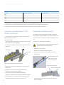
1
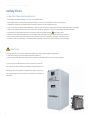
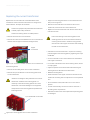
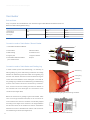
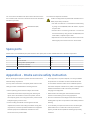
GE
Industrial Solutions
Gear
24kV-27kV
Air Insulation Switchgear
User Manual
Index
General
2
Summary
2
Standard and Specification
2
Operating Conditions
3
Safety and Environment Protection Requirement
3
Handling and Storage
4
Installation of Switchgear
6
Technical Specification
7
Technical specification for SecoGear Table 1
7
Technical specification for SecoVac VB2 Plus (Circuit breaker) Table 2
7
Main circuit resistance of SecoVac VB2 plus Table 3
7
Technical specification for Earthing switch Table 4
8
Resistance to internal arc faults (Optional)
8
Keylock (Optional)
8
Padlock (Optional)
10
Enclosure design and equipment
11
Typical Modules (Figures 3/1)
11
Enclosure and Partitioning (Figure 3/2)
11
Switchgear Structure
12
Cable Connections
15
Operations and trouble shooting
16
Operations and trouble shooting
16
Rack Circuit Breaker out from Service Position to Test / Disconnected Position
17
Circuit Breaker
18
Earthing Switch Operation
18
Interlocking of the Switchgear
19
Debugging of Combined Overcurrent Relay
20
Inspection and Maintenance
21
Summary
21
Inspection and Maintenance Interval
21
Diagnosis and Trouble Shooting for Malfunction During Operations
22
Maintenance Item and Cycle
22
Routine Inspection
22
Service
23
Repairs
24
Inspection Items
24
Performance Test
24
Major Repairs and Examples
25
Inspection and replacement of the main busbar
25
Inspection and replacement of the fixed contact and spout bushing
26
Inspection and replacement of the shutter mechanism
27
Replacing the earthing switch
27
Replacing the current transformer
29
Inspection and replacement of the surge arrester
30
Main Busbar
31
Spare Parts
32
Appendix A - Onsite Service Safety Instruction
32
SecoGear 24kV-27kV Air Insulation Switchgear
Safety first!
Important Recommendations:
• Switchgear should be installed in a clean, dry, ventilated room.
• Switchgear and/or switchboards should be installed in closed rooms suitable for electrical equipment.
• Installation, operation and maintenance should be carried out by licensed electricians.
• Fully comply with the applicable standards (e.g. IEC), the utility connection requirements and the applicable safety regulations.
• Observe the relevant instructions in the instruction manual for all actions in relation to switchgear and switchboards.
warning symbol.
• Pay attention to the hazard notes in the instruction manual marked with this
• Make sure that the specified data are not exceeded under switchgear or switchboard operating conditions.
• Keep the instruction manual accessible to all personnel involved in installation, operation and maintenance.
• The users must act responsibly in all matters affecting safety at work and correct handling of the switchgear.
Warning
• Always follow the instruction manual and respect the rules for good engineering practice!
• Hazardous voltage can cause electrical shocks and burns.
• Disconnect power, then earth and short-circuit before proceeding with any work on the equipment.
If you have any further questions about this instruction manual,
our field team will be pleased to provide the required information.
GE Energy reserve all rights to this publication. We do not accept
any responsibility for the information provided, which is subject to
alternation.
1
SecoGear 24kV-27kV Air Insulation Switchgear
General
Summary
This publication contains the information required for
switchgear, such as the technical data, detailed part lists for the
installation, commissioning, operation and maintenance
individual panels and comprehensive circuit documentation etc.,
of SecoGear. SecoGear is three-phase, metal enclosed, air-
can be found in the relevant order documents.
insulated factory assembled switchgear. SecoGear is typetested and suitable for indoor applications up to 27 kV. The
For correct usage of the switchgear, please read this manual
panel is designed with withdrawable modules and is fitted with
carefully. It is always advisable to use the manual for all
a single busbar system. The withdrawable parts are equipped
operations regarding installation, commissioning, operation and
with circuit breakers, voltage transformers, fuses or current
maintenance of SecoGear air-insulated switchgear.
transformers.
These instructions are also used as references for personnel to
Details of the technical design and configuration of individual
carry on regularly maintenance of the switchgear.
Standard and Specification
• SecoGear complies with the standards and specifications for factory-assembled, metal enclosed and type tested high voltage
switchgears to IEC publications as given below.
IEC62271-100: 2008
…………… High-voltage alternating current circuit breakers.
IEC62271-200: 2003
…………… AC Metal enclosed switchgear and control gear for rated voltages above
1kV and up to 52kV.
IEC62271-102: 2001
…………… High-voltage alternating current Disconnector and Earthing Switches.
IEC62271-1: 2007
…………… The common specification for high voltage switchgear and control gear
simple Standards
IEC60529:1989
…………… Degrees of protection as provided by enclosures (IP Code)
The switchgear has the following degrees of protection:
IP 4X applies for the enclosure and IP 2X applies for the partitions.
All other corresponding IEC publications, national or local safety regulations must be followed during the installation and operation of
the switchgear. In addition, any project specific advice from GE must be considered.
2
SecoGear 24kV-27kV Air Insulation Switchgear
Operating Conditions
Normal operating conditions
The switchgear is fundamentally designed for the normal service conditions for indoor switchgear to IEC Publication 62271-1:2007. The
following limitations apply. (If there are others we should detailthe limitations)
• Ambient temperature
- Maximum
+ 40℃
- 24h-Medium
+35℃
- Minimum
-15℃
• The maximum site altitude is 1000 m above sea level
• Humidity
- Highest average value measured over 24 hours
o Relative humidity
95 %
- Highest average value measured over 1 month
o Relative humidity
90 %
• The intensity of earthquake should not exceed level 8
Special operating conditions
Note on any special climatic operating conditions
SecoGear is suitable for operation in the climate of indoor
When the switchgear is operated in areas with high humidity
type according to IEC 62271-200 standard. Special operating
and/or major rapid temperature fluctuations, there is a risk
conditions must be discussed with the manufacturer in advance.
of condensation. Preventive actions (e.g. applying an electric
For example: At site altitudes above 1000 m, the effects of the
heater) must be consulted with the manufacturer to avoid
reduction in density of air on the dielectric properties must be
condensation and any resulting corrosion or other adverse
taken into account.
effects. The control of the heaters depends on the particular
Increased ambient temperatures must be compensated for in
project are available.
the design of the busbar and the branch conductors as well as
the withdrawable parts; otherwise the current carrying capacity
will be reduced. Fitting additional ventilation facilities can assist
heat dissipation in the switchgear panel.
Safety and Environment Protection Requirement
Safety Procedure
• Wear safety uniform according to electric safety regulations before entering the site
• Comply with industry work procedure. Power supply shall be operated by authorized staff.
Environment protection requirements
The manufacturer has a product recycle policy in accordance
with related law and ISO14001. Local laws shall be observed
when the switchgear is due for recycle.
3
SecoGear 24kV-27kV Air Insulation Switchgear
Handling and Storage
Condition on delivery
Transport
At the time of dispatch, the factory assembled SecoGear will
The transport units normally comprise of individual panels and,
have withdrawable parts either securely locked in the service
in exceptional cases, small groups of panels. The panels are
position or packed separately, depending on the rating of the
equipped with four (4) lifting eyebolts.
equipment, transport mode and destination.
Only carry out loading operations when all precautionary
The SecoGear panels are verified in the factory for completeness
measures to protect personnel and materials have been taken,
as per order requirement, and also passed routine testing as per
with the following equipment:
IEC 62271-200.
The busbars are not assembled, they are packed separately with
fasteners and accessories.
• Crane of suitable capacity; the minimum capacity shall be 2
tonnes
• Fork-lift truck and/or manual trolley
• Lifting ropes/slings of appropriate load capacity with shackles
Packing
Based on the kind of transportation and country of destination,
• Maintain an angle of at least 60° from the front for the ropes
leading to the crane hook (Figure 1/1)
the packing may vary. To protect against moisture a drying
agent bag is provided. IEC62271-1:2007 guidelines are followed.
HANG THE UNITS USING ALL 4 EYEBOLTS!
• Panels with basic or no packing
• Panels with seaworthy or similar packing (including packing
for containerized shipments)
o Sealed in polyethylene sheeting
o Transport drying agent bags included
o Moisture indicator included
• Observe the directions for use of the drying agent bags. Note
the following
o Drying agent color observed blue indicates the packaged
equipment is dry condition
o Drying agent color observed pink indicates the packaging
contains moisture (relative humidity above 40%). Please
Figure 1/1: Handling by crane
contact the manufacturer in this case before installation
(1) Lifting eyebolts (qty.4)
4
SecoGear 24kV-27kV Air Insulation Switchgear
Upon Receipt
The responsibilities of the consignee when the switchgear arrives at the site include, but are not limited to, the following:
Check the consignment is complete and without damage (e.g. look for any adverse effect caused by moisture). In case of doubt, the
packing must be opened and then properly resealed with new drying agent bags (when intermediate storage is necessary).
If any quantities are short, or defects or transport damage is noted, these must be;
• Documented on the respective shipping document
• Notified to the relevant carrier or forwarding agent immediately in accordance with the relative liability regulations
Note: Always take photographs to document any major damage.
Intermediate storage
Intermediate storage should follow the following practices to avoid any negative consequences:
Panels with basic packing or without packing
Panels with seaworthy or similar packing with internal protective
• A dry well-ventilated storeroom with a climate in accordance
covers
with IEC62271-1:2007
• Store the transport units
• Store the panels upright
a. Protected from the weather
• Do not stack panels
b. In a dry place
Panels with basic packing;
c. Safe from any damage
• Open the packing, at least partially
• Check the packing for damage
Panels without packing;
• Check the drying agent;
• Loosely covered with polythene
d. On arrival of the consignment
• Ensure that there is sufficient air circulation
e. Subsequently at regular intervals
Check regularly for any condensation during storage.
When the maximum storage period (starting from the date of packing) has been exceeded
• The protective function of the packing can no longer be guaranteed
• Take suitable action if intermediate storage needs to be continued
Warning
Do not walk on the top of the panels (due to rupture points in pressure
relief devices) ! The pressure relief devices can be damaged!
5
SecoGear 24kV-27kV Air Insulation Switchgear
Installation of Switchgear
Basic Frame
In order to obtain an optimum installation sequence and ensure
800
600
personnel and monitored by responsible persons.
1800
1700
800/1000
only be carried out by specially trained, or at least by supervised
1800
1700
800/1000
high quality standards, site installation of the switchgear should
Basic Frame
Switch room cable duct arrangement (Side elevation)
Power Cable Duct
must be fundamentally finished, provided with lighting and the
electricity supply, lockable, dry and with facilities for ventilation.
Power Cable Duct
On commencement of installation on site, the switch-room
It is also required that the basic frame and indoor ground
for the switchgear should be checked and accepted before
the construction. It must be ensure that the ceiling height is
sufficient for the opening travel of the pressure relief plates.
800
30
Tolerances for laying the floor frame are:
1800
70
800
1800
30
150
70
150
Evenness tolerance: ± 1mm within a measuring length of 1m.
Straightness tolerance: 1mm per 1m, but not more than 3mm
over entire length of frame.
Cross section view of switchgear room layout (plan
view)
Connection betweenSwitchgears
In order to connect the different switchgears together, here
use bolts of M8×35 to connect the panels together, the torque
requirement for the bolts is 26 N∙m, the connection points on the
1900
1800
70
switchgear is shown below.
2400
800
30
Top Curface of basic frame
3~5mm above ground
Basic Frame
140
130
+5.0m
300
250
1200
Strap of control cable duct
Figured steel plate (t=5mm)
Control Cable Duct 250*250
800
290
v
800
Power Cable Duct 800*1000
Detail of switchgear cable access cutout
1800
1700
Connection Points betweenSwitchgears
54
A
B
4-15x20
144
358
190
130
Power Cable
Control Cable
Width
A
B
C
Dimension
800
600
595
1000
800
692
6
SecoGear 24kV-27kV Air Insulation Switchgear
Technical Specification
Technical specification for SecoGear -Table 1
Rated voltage
kV
24
27
Rated power frequency withstand voltage
kV
50
65
Rated lightning impulse withstand voltage
kVp
125
Rated frequency
Hz
50/60
Rated current
A
1250/2500
Rated short time withstand current(3s)
kA
31.5
Rated peak withstand current1)
kAp
Resistance
82
≤ 110 ( ≤ 1600A)
uΩ
IP level for weather protection
125
≤ 85 ( ≥ 2000A)
Enclosure
IP4X
Between compartment
IP2X
Technical specification for SecoVac VB2 Plus (Circuit breaker) -Table 2
Rated voltage
kV
24
27
Rated power frequency withstand voltage
kV
50
65
Rated lightning impulse withstand voltage
kVp
125
Rated frequency
Hz
50/60
Rated current
A
1250/2500
Rated short-circuit breaking current:
kA
125
31.5s
Percentage of DC component
Up to 52%
Rated short-circuit closing current
kAp
82
Rated short time withstand current
kA
31.5
Rated peak value withstand current
kAp
82
Rated duration time for short-circuit
s
3
Opening Time
ms
20 ~ 50
Closing Time
ms
30 ~ 70
V
24*/30*/36/48/60/110/220 V DC 110/220 V AC
Rated auxiliary control voltage
Operation sequence:
O-0.3s-CO-15s-CO/ O-0.3s-CO-180s-CO
Mechanical life operations:
Times
Electrical Endurance
Class
E2
A
400
Single Capacitor Switching current
10000 (M 2)
*Consult with GE
Main circuit resistance of SecoVac VB2 plus -Table 3
7
Item
Unit
Rated current
A
1250
Value
2500
Withdrawable
µΩ
≤ 45
≤ 25
SecoGear 24kV-27kV Air Insulation Switchgear
Technical specification for Earthing switch -Table 4
S/N
Specification
Unit
Data
1
Rated voltage
kV
24/27
2
Rated Work frequency withstand voltage (1min) in open condition of switch
kV
65
3
Rated Lighting impulse withstand voltage (peak value) in open condition of switch
kVp
125
4
Rated short-time withstand current (3s)
kA
31.5
5
Rated peak value withstand current
kAp
82
6
Rated short circuit making current
kAp
82
7
Centre distance between phases
mm
220/255
8
Electric endurance
Class
E1
9
Mechanical endurance
Times
2000
Resistance to internal arc faults
Arc release
All three primary compartments of SecoGear switchgear are
31.5kA/1s
provided with pressure relief flaps, which will automatically open
and guide the pressurized gas to the rear side direction if an
internal arc fault occurs in an affected compartment
The pressure relief protects damage to switchgear components
and the risk of injury to personnel, which may endanger an
operator or extend the arc fault effect to the entire switchgear
lineup. The relief flap is fixed by 3-M8 steel bolts and the other
side is fixed by plastic M6 screw, The M6 screw will be broken
and flap will open along weakness area( No bend area and part
with oblong holes) when pressure increase quick by internal arc
Keylock (Optional)
The use of key interlocks is to realizing the interlocking logics between units of switchgear, Also the functional truck can be locked in
the racked-out position and the relevant lock key can only be removed with the functional truck in disconnect position. The earthing
switch closing and opening operations can be locked by means of keys. The latter can only be removed with the earthing switch in an
opposed position to the lock to be made.
8
SecoGear 24kV-27kV Air Insulation Switchgear
Description of the interlock system
Functional truck racking-in lock
Earthing switch closing lock
Earthing switch opening lock
Key Condition
Key will be free when the truck in the disconnect position
Key will be trapped when the truck in the rack-in position
Key will be free when the Earthing switch is open
Key will trapped when the earthing switch in closed position
Key will be free when the Earthing switch closed
Key will trapped when the earthing switch in open position
Figure : Functional truck racking-in lock
Key lock is locked, key is free, Truck indisconnect position
Key lock can't be locked when truck in rack in position, and key is trapped
Figure 2/5: Earthing switch in open position
When earthing switch in open position, earthing switch can be locked by closing lock, the key of closing lock can be free. And opening
lock can't be locked, the key of opening lock is trapped.
Figure 2/6: Earthing switch in close position
When earthing switch in close position, earthing switch can be locked by opening lock, the key of opening lock can be free. And closing
9
lock can’t be locked, the key of closing lock is trapped.
SecoGear 24kV-27kV Air Insulation Switchgear
Padlock (Optional)
Padlock for Circuit breaker racking-in/out operation
Padlock for Circuit breaker racking-in/out operation will limit the access to insert crank lever to racking-in/out Circuit breaker. Rackingin/out operation can be done only when lock cover is in the open position.
Figure 2/9: Padlock for Circuit breaker racking-in/out operation
Padlock for earthing switch operation
Padlock for earthing switch operation will limit the access to inserting the operation lever to operate earthing switch. Open/close
button can be operated only when the lock cover is in the open position.
Figure 2/8: Padlock for earthing switch operation
10
SecoGear 24kV-27kV Air Insulation Switchgear
Enclosure design and equipment
Typical modules (Figures 3/1)
With withdrawable type SecoVac VB2 Plus Vacuum
Circuit Breaker installed, SecoGear panels are used for
incoming or outgoing feeder. Each unit consists of three
high voltage compartments; Main bus bar, Circuit breaker,
Cable compartment and one Low voltage compartment for
instruments and auxiliary circuits.
For busbar sectionalizing, two panels are necessary, the
coupling panel with the withdrawable circuit breaker part and
a bus riser panel (available with busbar metering and earthing).
In equipment without busbar sectionalizing, a direct bar
connection between the individual panels will be provided.
Figure 3/1: Typical modules
Enclosure and partitioning
High quality 2mm thick Alu-Zinc steel sheets is used for the
• Figures of the panel (Refer to figure 3/2), the floor of the cable
external enclosure and internal partitions. Pressure relief
compartment is fitted with removable non-magnetic metal
flaps are provided on the top of the panel for all high voltage
(13).
compartments. In case of overpressure due to internal arc
• The rear wall of the busbar compartment (3), intermediate
inside any of the compartments, these pressure relief flaps are
wall (14), mounting plate with shutters (16) and horizontal
designed to open quickly to release the pressure. The pressure-
partition (20) form part of the internal partitioning.
relief flaps are secured with steel screws on one side and
• The earthed internal partitioning ensures safe access to the
with plastic screws on the other side. In the case of internal
circuit breaker and cable compartment (C) even when the
overpressure, the plastic screws are the point of rupture caused
busbars are energized.
by arc conditions. The top mounted pressure relief flaps on the
enclosure are made from mesh metal.
All compartments are accessible from the front, with their
• The low voltage compartment (D) is fully protected from the
high voltage area with the earthed steel-sheet casing.
• On the end sides of the switchgear, end cover plates are
own independent doors. The front doors can be opened up to
provided for consistent appearance, as well as mechanical
an angle of 130° and they are arc resistant. An inspection
and thermal strength in case of internal arc fault in the end
window made of security glass is provided on circuit breaker
panel.
compartment door. The panel design provides an air gap
between two adjacent panels after panels are joined together.
• Doors, rear walls and cover plates are treated against
corrosion and then coated with high quality paint. The doors
for circuit breaker and cable compartment are arc resistant
with a mechanical interlock.
11
SecoGear 24kV-27kV Air Insulation Switchgear
Switchgear structure
1
P30
P32
1. Pressure relief plate
12
2. Enclosure
3. Cover of main busbar compartment (can be removed)
5
2
4. Branch busbar
D
A
5. Main busbar
3
B
4
6
7
15
6. Primary disconnect spouse
14
7. Primary disconnect
16
8. Current transformer
9. Earthing switch
8
17
18
40
9
22
10
17
11. Bottom plate
12. Partition between breaker compartment and busbar
13
C
10. Rear door interlock
19
compartment
13. Terminal block
14. Control plug
11
20
15. Shutter
Figure 3/2: Typical feeder panel
16. Vacuum circuit breaker
A. Main bus compartment
17. Drive screw
B. Breaker compartment
18. Earthing switch operation mechanism
C. Cable compartment
19. Control wire duct
D. Low voltage compartment
20. Main earthing busbar
10
SCALE
Figure 3/3: Incoming/feeder panel(1250/2500A)
1,000
Figure 3/4: Incoming With fix VT panel (1250/2500A)
12
SecoGear 24kV-27kV Air Insulation Switchgear
01
A
A
B
B
C
C
SCALE
SCALE
1,000
1,000
Figure 3/5: Busbar tie panel(1250/2500A)
Figure 3/6: Riser panel(1250/2500A)
JSZV17-15R
JSZV17-15R
15
76
76
95.5
95.5
15
01
Figure 3/7: Measuring panel(1250/2500A)
13
Figure 3/8: VT Panel (2500A)
SecoGear 24kV-27kV Air Insulation Switchgear
Figure 3/9: Incoming with ES & VT panel (1250/2500A)
Figure 3/10: Riser with ES panel (1250/2500)
Figure 3/11: CPT panel (2500A)
Figure 3/12: Typical dimensions and Weights of SecoGear
(including withdrawable circuit-breaker parts)
Dimension in
mm
Description
27kV
Height
A
Rated current of branch 1250A 31.5kA
Width
VT
800
Weight
A
Kg
1250
800-1000
2500
1000-1200
B
Rated current of branch 2500A 31.5kA
Depth
2400
Rated current
1000
C
1800
14
SecoGear 24kV-27kV Air Insulation Switchgear
Cable Connections
The cable compartment contains current transformers, voltage transformers (fixed or withdrawable), and earthing switch, depending
on the individual operating requirements.
The cable compartment is constructed for installation of three current transformers. When all the three current transformers are not
required, dummies can be installed in their place to maintain the same installation and connection procedures.
The fixed or withdrawable voltage transformers are connected with busbar on the primary side and fitted with HRC fuses. The earthing
switch can be operated manually, with position indication by mechanical indicator on the driveshaft and auxiliary switch. Three
lightning arrestors (optional) can be mounted in the space available.
Cable connection:
Rated voltage
Panel width
Max. number of parallel cables
Max. cross section of cables
Range of cable clamp
Range of reducer ring
(kV)
(mm )
per Phase
(mm2)
(mm)
(mm)
630
35-54
27-62
27
800
6
1000
6
4
3
NO.
Parts Description
1
Cable clamp
2
Main earthing bar
3
Cable connection bar
4
Earthing Switch
2
1
Figure 3/13: Cable compartment layout
15
This cover has been interlocked with the earthing
switch and can be opened only when the earthing
switch is in closed position
Earthing switch can be opened only when rear cover
is closed
SecoGear 24kV-27kV Air Insulation Switchgear
Operations and trouble shooting
Operations and trouble shooting
Before start up, the following work should be completed:
a. Check the overall condition of the switchgear and clear any
potential risk factor.
h. Remove the shipping cap on the pole of the circuit breaker.
i. When testing the power frequency withstand voltage of main
b. Check the switch,truck,isolated contactor and insulating
parts etc. by visual inspection.
circuit, pay particular attention to sensors, cables and other
equipment during the test process.
c. Check the connection between earthing bus bar and
Attention: Read the product manual carefully when testing
earthing conductor of the transformer substation outside the
the VT withstand voltage; use a test voltage of appropriate
compartment is secure.
frequency to avoid core saturation.
d. Remove all of the remaining materials, unnecessary objects
and tools inside of the compartment.
j. Place the Circuit Breaker on auxiliary control power.
k. Perform the operation test of the circuit breaker by manual or
e. Wipe the compartment body and the insulation parts with
electric control; observe the corresponding position indicator.
a soft cloth that should be clean and dry. Then wipe off any
l. Check the interlocking validity, both mechanical and electrical.
remaining dust and grease.
m.Conductive paste can be applied on the circuit breaker
f. Clean the surface of earthing busbar. The earthing loop
primary contacts.
resistance should be less than 350 micro-ohms.
g. Re-install the cover removed during the period of installation,
wiring and commissioning.
Warning
a. Comply with all relevant safety regulations
b. Maintain circuit breakers in disconnection position
c. Remove earth wires and short wires of the hazardous areas
d. Pay attention to any abnormal situations
Use of hand tools
1) Gear door lock key
2) Rack handle for truck
3) Earthing switch operation handle
drawing no: 5GD.253.008
drawing no: Y-002
drawing no: 5GD.253.144
FIG 20 : Hand Tools
16
SecoGear 24kV-27kV Air Insulation Switchgear
Rack Circuit Breaker out from service position to test / disconnected position
Move circuit breaker truck from transfer truck into the switchgear
a. Check the fixed primary contact and apply an adequate
amount of conductive paste. Check the interlocking
Warning
mechanism and apply lubricant on the moving parts to ensure
The trolley has four (4) nuts for adjusting the platform, to
smooth operation.
the same level of the breaker compartment.
b. Place the Circuit Breaker on transfer truck and put in lock
position. (See figure 4/1).
d. Push the two sliding cranks inward under the truck to remove
the locked position with the transfer truck, and then push the
truck forward to make it enter the switchgear compartment
VCB locked on
and lock it in the disconnect / test position. (See figure 4/4).
the transfer truck
e. Operate the lock key releasing lever of the transfer truck to
Figure 4/1: VCB truck on the transfer truck
c. Move the transfer truck to the front of the switchgear, turn
the adjusting nut to adjust the height of the transfer truck
platform, (See figure 4/2). Aim the guiding pin at the guiding
Figure 4/4: Lock VCB in switchgear
jack in front of the switchgear, push and make the transfer
truck engage with the switchgear by using the lock key. At
remove the locked relation between the transfer truck and the
the same time, insert the front guide rail of the transfer truck
switchgear, and then remove the transfer truck.
into the bottom guide rail groove of the switchgear truck. (See
figure 4/3).
17
Figure 4/2: Transfer truck lock
Figure 4/3: Lock VCB in
with switchgear
switchgear
SecoGear 24kV-27kV Air Insulation Switchgear
Move the truck from disconnect / test position to service position
a. Make sure the front and back door of the switchgear are
closed. Make sure the earthing switch is in the open position,
Warning
the circuit breaker compartment is clear and without any
The truck is not allowed to be placed in any intermediate
unexpected object.
position between disconnect/test position and operating
position.
b. Insert the secondary plug of the truck into the socket on the
topside of the switchgear truck compartment and put into the
lock position. (See figure 4/5 & 4/6)
Move the Circuit Breaker from service position to test
position
a. Make sure the circuit breaker is in open position.
b. Perform the operating steps for moving the Circuit Breaker
into operation position in reverse order.
Figure 4/5: Take off secondary
plug from truck
Move the Circuit Breaker from switchgear
compartment to transfer truck.
Perform the operating steps for moving the Circuit Breaker truck
from transfer truck into the switchgear in reverse order.
Figure 4/6: Put the secondary
plug into switchgear socket
c. Make sure the circuit breaker is in the open position.
d. Insert the racking crank of the truck into the rectangular
cranking hole of the screw mechanism of the truck through
the operation hole under the door of the circuit breaker
compartment. (See figure 4/7).
Circuit breaker
For operating instructions refer to the Circuit Breaker instruction
manual.
Earthing switch operation
The earthing switch has a rapid close-open mechanism, which
is independent to the rotation speed of the earth switch drive
shaft.
The closing brake function can be quickly applied through
Figure 4/7: Rack in the breaker
to work position
the rapid close-brake mechanism. The earthing switch, circuit
breaker truck and rear cover behind the panel have a closedown
device to prevent incorrect operation.
e. Turn the crank clockwise (approximately 20 turns) until it can't
The earthing switch can be operated only when the truck is in
be moved any more, listen for a strong cranking sound when
disconnect / test position and the rear cover of the switchgear is
the breaker changes into the operating position.
in the closed position.
f. The position indicator on the door of the low voltage
compartment shows the breaker is in service position.
The operating hole of the earthing switch located in the lower
position of the right side in front of the panel. (See figure 4/8).
g. Take off the racking crank. The racking operation is now
complete.
18
SecoGear 24kV-27kV Air Insulation Switchgear
Open the earthing switch
Warning
Make sure the cable compartment is clear and without
any unexpected objects
Make sure the cable compartment door is closed
The earthing switch has been interlocked with the rear
cover of cable compartment and can be opened only when
the cover is closed.
If found the operation of earthing switch become hard, do
not apply the excessive force. This can cause damage to
the parts. Ensure the cover is properly secured and then
operate the earthing switch.
Contact the manufacturer, if the problem still exist.
completely
• Insert the earthing switch operating handle, and turn the
handle 180° counterclockwise to open the switch (See figure
4/10)
• Check the mechanically interlocked label and indication light
Figure 4/8: Earthing switch operation warning
to ensure the earthing switch is fully open
Close the earthing switch
Interlocking of the switchgear
• Check that the voltage presence indication on the low voltage
• The circuit breaker can be closed only when fully engaged in
compartment is off.
the test or service position
• Check other electrical interlock, if applicable, to allow the
operation.
• The control plug can be released when the circuit breaker is in
test or disconnected position. The secondary plug is latched
• (See figure 4/9) Lower the operating hole shutter and insert
when the circuit is in service position (see figure 4/11)
the operating handle, and turn the handle 180° clockwise to
close the earthing switch.
Figure 4/11: Secondary plug latch
Figure 4/9: Close earth switch
Figure 4/10: Open earthing switch
• Front Break is released only when operating lever is inserted;
and operating lever cannot be inserted when undercarriage is
• Ensure the earthing switch is fully closed.
Warning
Check the position indicator on low voltage compartment
door
Check the flag adjacent to the earthing switch operating
19
hole
in test position
• Undercarriage Interlock is released only when undercarriage
is in test position
• Undercarriage and ES interlock insures undercarriage can be
in service position only when ES is OFF
• Back Break insures ES can be switched only when back door
is closed
• Back Door Interlock is released only when ES is ON
SecoGear 24kV-27kV Air Insulation Switchgear
Interlock with Rear door
Interlock with VCB
undercarriage door
Padlock cover for ES operation
Fig 4/12 Earthing switch interlock with rear cover
Fig 4/13 Breaker interlock with undercarriage
SEQUENCE OF EARTHING SWITCH OPERATION
Closing the earthing switch:
Press the handle slide downwards; insert earthing switch operation handle
and turn the handle 180 degree clockwise to close the earthing switch,
Opening the earthing switch:
Press the handle flap downward, insert earthing switch operation handle
and turn the handle 180 degree counter clockwise to open earthing switch.
The flap will be in lower position when earthingn switch is open
1. Operation Lever Insert Socket
2. Front Break
3. Undercarriage Position Interlock
4. Undercarriage and ES Interlock
5. Front Operation shaft
6. Back Break
7. Back Interlock Shaft
8. Back Door Interlock
Fig 4/14: Earthing switch interlock VCB truck and Rear door
20
SecoGear 24kV-27kV Air Insulation Switchgear
Inspection and maintenance
Summary
Inspection and maintenance interval
After the process of installation and testing, the switchgear
The maintenance interval determined by operating conditions of
is available to use. Timely and proper maintenance can keep
the switchgear depends on the operating mode, the operating
the switchgear trouble-free and can prolong the life of the
number of rated current and short circuit current, environment
switchgear as long as possible.
temperature and pollution.
The maintenance work must be carried out by certified persons
The recommending maintenance interval is showed in the
who are familiar with the related operations of the switchgear
following table:
and understand relevant IEC and other local safety rules and
maintenance content
interval(years)
as well. Allow a GE representative to assist when the switchgear
inspection
2~31)
and its components need to be repaired. Users should think
care and maintenance
2~32)
important guides established by other technical departments
about the operating environment and the operation frequency
when developing maintenance rules. Usually the inspection of
some equipment / components (such as wearable parts) and
the maintenance intervals (maintenance period) depend on
the running time, operating frequency and the number of short
circuit cycles. The maintenance period of other parts depends on
the working situation, the degree of the load and environmental
impact (including pollution and corrosive gasses).
21
according to the operation
cycle of circuit breaker
50003)
1) Recommended shorter interval years when operated in very
severe running conditions.
2) According to inspection results.
3) Refer to the VCB manual.
SecoGear 24kV-27kV Air Insulation Switchgear
Diagnosis and trouble shooting for malfunction during operations
Malfunction
Reason
Resolution
1. The handles on the withdrawable frame is not
in position.
2. The circuit breaker is closed
The circuit breaker can not be racked into service
3. The earthing switch is closed
position from test position
4. The circuit breaker is electrically interlocked
(electromagnetic Y0 locked)
5. Shutter is not completely open
The circuit breaker can not be racked out to test
position from service position
1. The circuit breaker is closed
2. The circuit breaker is electrically interlocked
(electromagnetic Y0 locked)
1. Adjust the frame and handles
2. Open the circuit breaker
3. Open the earthing switch
4. Unlock /Check electromagnetic Y0
5. Check shutter drive mechanism
1. Open the circuit breaker
2. Unlock /Check electromagnetic Y0
1. The circuit breaker is not in test / disconnected 1. Rack the circuit breaker out to test position or
Can not lower the shutter on the earthing switch
position
disconnected position
operating hole
2. The earth switch is electrically interlocked
2. Unlock / Check electromagnet
Operating hole shutter can not rise back after
the earthing switch is opened
Drive shaft of earthing switch has not reached
intended position
The cable compartment door can not be closed / The earthing switch is not completely
opened
opened
Turn the crank anticlockwise to the limit where
the mechanical OPEN indication stays exactly
below the operating hole
Open the earthing switch
The circuit breaker can not be closed
1. No auxiliary power supply
2. The control plug is not inserted
3. The circuit breaker is not engaged in test /
service position
4. The closing spring has not been charged
5. The electrical interlocking in position
6. Closing release not working
1. Turn on auxiliary power supply
2. Insert and lock control plug
3. Fully engage the circuit breaker to test /service
position
4. Charge the closing spring
5. Check power supply for interlocking
6. Check power supply for closing release
The circuit breaker can not be opened
1. No auxiliary power supply
2. Opening release not working
1. Turn on auxiliary power supply
2. Check power supply for opening release
Maintenance item and cycle
Routine Inspection
Maintenance of the switchgear should be carried out by
Safety measure: Routine inspection is to ensure smooth
trained personnel, who are familiar with the switchgear
operation of the switchgear. It does not require power
characteristics, in accordance to the manufacturer's
shutdown, but requires care to prevent incorrect
instructions and IEC standards.
operations.
It is recommended any major repairs (if required) shall be
The purpose for routine inspection is to find issues in advance so
assisted by the manufacturer or a qualified representative.
they can be resolved immediately.
22
SecoGear 24kV-27kV Air Insulation Switchgear
Routine inspection includes:
The purpose for the service is to guarantee the operation quality
• Check compartment doors are closed properly
of the switchgear and avoid any possible malfunctions. This
• Verify the control voltage, auxiliary voltage and battery
increases the life of the switchgear. The scope of work is as
voltage are in normal condition
follows:
• The status indication and position indication for the circuit
breaker and earthing switch etc are normal
• Inspection: Determination of the actual condition
• Servicing: Measures to preserve the specified condition
• Check ammeter and voltmeter on the display
• Repair: Measures to restore the specified condition
• Check relay indications. (The power indication should be on
The service interval for the switchgear depends on external
and fault indication should be off.)
• Check alarm and pre alarm indications
factors including the operating environment, the operation
• Partial discharge should not occur on the surfaces of
frequency and service age etc.
equipment at operating voltage. This can, for example, be
detected by characteristic noises, a clearly perceptible smell
of ozone, or visible glowing in the dark;
• Check the heater condition, if installed. The relay monitoring
the heater current is in the low voltage compartment. Check
It is recommended to have switchgear serviced
every 2-3 years, if installed in good environment and
not frequently operated.
the heater circuit if the red current indication turn off due to
It is recommended to have switchgear serviced
every year, if operated more than 10 times a month.
the heater losing power supply. (see figure 5/1)
Heater current
indication
Figure 5/1: Heater current monitoring relay
It is recommended to have switchgear serviced
every half year, if installed in adverse environment
and frequently operated.
It is recommended to have the circuit breaker
replaced, if reached its mechanicall operating cycles
or rated short circuit breaking times.
If any abnormal condition is found, then the cause must be
identified in order to restore normal condition.
It is recommeded to inspect the circuit breaker every 6
months if in stand-by for a significant period of time.
Service
Safety measure: The power must be shutdown before
scheduled switchgear service, and the work area
must be isolated. Measures must be taken to disallow
the power being switched on. Ensure proper earthing
and padlocks in place. Specially trained personnel are
required to supervise.
23
SecoGear 24kV-27kV Air Insulation Switchgear
Repairs
Immediate repairs are required in case of following situation emerges:
• Deteriorated insulation, discharges, flashover and breakdown
• Damaged component in the switchgear
• Any other abnormal observation which may affect safety
Inspection Items
• Check all the compartments and internal components for
dampness, rust and dirt.
• Check the fixed contact including its profile for any sign of
sparking or wear-and-tear.
• Check the tightening torques of the busbar bolted connections
on selected samples.
• Check the shutter mechanism in the circuit breaker
compartment.
• Remove the pressure flaps on the busbar compartment and
remove the insulation shield (See fig 5/2). Check the torque is
86 N-m using a torque wrench.
• Check the interlocking between the circuit breaker and the
earthing switch.
• Check the bolted connection between the power cable
connectors and lugs.
Insulation
shield (for side
panel)
Insulation shield
(Middle panel)
• Check earthing switch operation.
• Check the interlocking between the earthing switch and the
cable compartment door.
• Check the interlocking between the circuit breaker and the
breaker compartment door.
• Check live voltage indications.
• Check the heater (If installed).
Figure 5/2: Main busbar shield(Need to be replaced)
Performance test
Performance test is to validate the electrical performance of the switchgear. It is recommended to be carried out together with the
scheduled service.
Performance test includes:
• Close and open the circuit break for five times, and check the circuit
• Check all the interlocking mechanism
• Electrical test including power frequency withstand test, CT/VT ratio and the contact resistance for the circuit break
• Verify mechanical characteristics of the circuit break
24
SecoGear 24kV-27kV Air Insulation Switchgear
Major Repairs and examples
Be sure to comply with the applicable safety
regulations when carrying out repairs.
• Open the main busbar compartment and check the tightening
• Remove the rear covers on the busbar compartment, as well
as the same on the adjacent panels. Now the busbar is visible.
(see figure 6/1)
torques for the busbar bolted connections
• Check the main busbar and branch busbar for any dampness
or rust.
• Check all the sidewalls for any dampness or rust.
• Check the main busbar compartment for any unexpected
object.
• Restore the insulation shield and the pressure flap on the top
of the panel.
• Check the fitness of the fixed contact and the surface
condition.
• Open the cable compartment and check the cable connection
Figure 6/1: Busbar after opening the rear cover
as wells as the connectors for color distortion.
• Check the sealing condition of through holes for the primary
and secondary cables.
• Check the heater condition.
• Check the breaker and cable compartment for unexpected
objects.
• Check the secondary connections of the CTs.
• Check the current terminals in the low voltage compartment
• Remove the pressure flap on the busbar compartment
• Remove the busbar insulation shield
• Remove the connection bolt on the main bar and branch
busbar
• Remove the busbar from the busbar compartment
• Install the new main busbar and fasten the joints
for the close loop of the secondary current circuit. Check
the protection relay, ammeter, energy meter, etc. on the CT
Pay attention to the direction of the tapered washers
secondary are in service.
and the bolted connection torque should reach 86 N-m.
• Cover the busbar joints with insulation shield
Inspection and replacement of the
main busbar
Unexpected objects in the busbar compartment, or a loose
bolted connection, may result heated joint or even phase fault.
The procedure to change the main busbar is as follow;
Verify the switchgear is de-energized and the safety
measures are in place.
25
• Reassemble the pressure flaps and rear cover panels for the
busbar compartment
SecoGear 24kV-27kV Air Insulation Switchgear
Inspection and replacement of the
fixed contact and spout bushing
It is normal to find the fixed contact surface oxidized due to
current flow and environmental factors during period of service.
However if the surface becomes rusty due to wet or corrosive
conditions, the fixed contact must be replaced. The spout
bushing may be replaced depending of its condition.
Clean the contact with a cotton-free paper, and apply some
pure alcohol if necessary. Brush small amount of contact
lubrication grease (DE-G51 for example) on the surface after
• Inspect the contacts. Replace the contact if the silver coating
on copper is worn, or the surface is corroded, damaged or
over heated.
• Remove the bolts on the fixed contact, and replace the fixed
contact (see figure 6/3)
• Replace the spout bushing
• Remove the bolt at the joint of the upper branch and main
busbar
• Remove the bolt at the joint of the lower branch busbar and
the current transformer
• Remove the center bolt of the fixed contact and then remove
the vertical connections
wiping. It is important to check any abnormal condition such as
the burning marks on the spout bushing, which may be caused
Silver plating fixed contact
Fixing screws
by the epoxy.
• Check and replace the fixed contact
Verify the switchgear is de-energized and the safety
measures are in place.
• Withdraw the circuit break . Open the shutter mechanism, and
insert two M8 bolts into the overlapping holes on the shafts
Front
Rear
Figure 6/3: Fixed contact and spout bushings
(See figure 6/2). Then the fixed contact along with the spout
bushing are visible.
• Remove four fixing screws (M12) of the spout and then the
spout can be removed (see figure 6/3)
• Replace the new spout bushing and fasten the fixing screws
(M12). Inject glass glue in the clearance between the spout
bushing and the mounting metal frame
• Insert the upper and lower branch busbar into the spout
bushing, and fix the fixed contact
Don't fasten the bolt initially when locking the fixed
contact, Please fasten by applying torque when the
upper branch and main busbar, lower branch and the
current transformer are fixed;
Figure 6/2 : shutter mechanism
Attention: The torque will be different based on different sizes of
the bolt and with/without lubrication. Corresponding torques of
different bolts identified below:
26
SecoGear 24kV-27kV Air Insulation Switchgear
Recommend torque (N-m)
Bolt size
Without lubrication (oil)
With lubrication (oil)
M8
26
10
M10
50
20
M12
86
40
M16
200
80
M20
300
120
• Tighten the bolt on the upper branch and main busbar. Ensure that applied torque is 86 N-m
• Tighten the bolt of the lower branch busbar and the current transformer. Ensure applied torque is 86 N-m
• Remove the inserted bolts on the driving mechanism of the shutter, and then put down the shutters
Inspection and replacement of the
shutter mechanism
Replacing the earthing switch
In case of distortion or deformation, the driving mechanism of
earthing switch along with labels for ON and OFF position, the
the shutter shall be replaced.
driving mechanism including driving gear assembly and drive
The steps as follows:
rod.
• Remove the split pins of the driving mechanism of the shutters
The steps for replacement are as follows.
and connection bar (see figure 6/5)
• Screw off the bolt which is used to fix driving mechanism (see
figure 6/4)
The replacing of the earthing switch includes changing the
Ensure switchgear is in Power OFF position and turn
the earthing switch to the ON position.
• Rack out the circuit breaker
Earthing bar
• Remove the compartment separating plate
Split pins
Bolt
• Remove the cover plate on the right side in the cable
compartment
Remove 6 fixing screws
which used to fix the
ES on the side sheet
Figure 6/4: Driving mechanism of the shutter
Remove 6 fixing screws
• Remove the 5 screws on the earthing bar, then remove the
earthing bar.
Remove 4 fixing screws
• Replace the 4 screws on the side plate of the shutter
mechanism, then remove the side plate.
• Remove the 6 screws which used to fix the shutter
mechanism, replace with the new parts of shutter mechanism.
• Now replacement can be done with the above instructions
following the previous instructions in reverse order.
27
• Loosen the fastening screws on the drive rod, but do not
remove completely.
SecoGear 24kV-27kV Air Insulation Switchgear
Both the screws can be accessed only when the
Fixed screw of
the bevel gear
earthing switch is in OPEN position
• Open the padlock on the operating hole of the earthing switch
• Draw out the drive rod forward, then the parts of the drive rod
in the switchgear can be removed from backwards now.
Attention: Don't fully remove the drive rod, otherwise all
the parts will fall out.
Figure 6/7: Fixing screw of bevel gear
• Completely draw out the drive rod from another side at a
Flexible connection
of the earthing
switch and earthing
busbar
slight angle.
• Loosen the 4 fixing screws on the fixing bracket (see figure
6/6), and then remove drive rod of the rear door interlock from
rear door, then draw out the drive rod backward.
Attention: Replace the bevel gear assembly and
earthing switch in the same way. Use care to avoid
damage as the main body is much heavier.
• Unscrew both of the bolts on the bevel gear (See figure 6/7).
Figure 6/8: Flexible cable between earthing Switch and earthing
busbar
• Unscrew the flexible connections between the earthing switch and common earthing busbar (see figure 6/8)
• Remove the fixing screw of the earthing switch, and then push the bevel gear and the main body of the earthing switch (See figure
6/9)
• Now replacement can be done with the above instructions following the previous instructions in reverse order.
Remove
screws o
6
fixing
f
the
earthing switch
Figure 6/9: Fixing screw of the earthing switch
28
SecoGear 24kV-27kV Air Insulation Switchgear
Replacing the current transformer
Replace the current transformer if the assembled current
transformer cannot meet the function due to a change in the
load conditions. The steps are as follows:
• Support the mounting plate of the current transformer and
then put on the ground
• Remove the four bolts which are used to fix the current
Confirm the equipment be powered off and make sure
to follow proper safety measures.
Confirm the earthing switch is in OPEN position.
transformer, and remove the current transformer
• Replace the current transformer with new one and screw on
with the four bolts
• Remove the back cover of the enclosure
Ensure the marking on the mounting plate for the
• Remove the connection bolt between the current transformer
installing position of the current transformer before
removing the four bolts to avoid the wrong position
and the vertical copper connections (See figure 6/10)
with the hole of the copper connections after installing
the new current transformer;
Copper
connections
• Assemble the current transformer in its place on mounting
plate and tighten the mounting plate by tightening the 10 pcs
of M8 bolts
• Screw on the bolts on the current transformer and the both
side copper connections
Figure 6/10: Connection busbar between current transformer
and earthing switch
• Fix the bolt of the fixed contact of the earthing switch, but do
not fully tighten.
• Adjust the position of the fixed contact after switching the
• Remove the secondary wires of the current transformer
• Remove the 6 pcs of M8 bolts on the mounting plate of the
current transformer
earthing switch in ON Position and then fasten
• OPEN the earthing switch
• Fasten the bolts on the copper connections and the current
Attention: The weight is heavy because of the current
transformer installed in the mounting plate. It is
necessary to hold the mounting plate of the current
transformer to avoid the damage for the equipment
and personnel if the mounting plate drops down after
loosening the bolt.
transformer mounting with a torque wrench at a torque of 86
N-m
• Fix the insulation shield, and make sure it is in a vertical
position
• Connect the secondary connection of the CT and cover it
according to the requirements
• Assemble the back cover and compartment separating plate
of switchgear
3 pcs of M8 bolts on each side
29
Figure 6/11: Mounting plate of the current transformer
SecoGear 24kV-27kV Air Insulation Switchgear
Inspection and replacement of the
surge arrester
Inspection and replacement of
potential indicator
It is necessary to replace the surge arrester based on big
If the display "Lock" on the potential indicator is flashing, and
difference between reference voltage and the test data recorded
an abnormal sound from the relay is continuously heard, there
on site during the maintenance and recording. The steps are as
may be two reasons that can cause this problem. First, there
follows:
may be a problem with the potential indicator contact. Second,
the display itself may have a fault despite three-phase power
condition.
Both of these situations demand to replace the display. The
steps are as follows:
Mounting
bracket
and
earthing bar for arrester
Lock indicator
Test push button
Figure 6/12: Installing surge arrester
• Remove the cable between the arrester and copper
Three phase c harged
display
Figure 6/14: Potential indicator
connection (See figure 6/12)
• Remove the fixed bolts on both sides of the mounting bracket
of the arrester
There are two types potential indicators. One is with latching
contact, and another is without the latching contact. The
• Push the three arresters and the bracket
replacement of the two types are the same. (See figure 6/14)
• Remove the fixed bolts on the mounting bracket of the
• Cut off the auxiliary power of potential indicator (if any)
arrester
• Disconnect all the connection from the back of the indicator
• Remove the lock of the potential indicator, and then push it
out (See figure 6/15)
• Replace with the new one, and fix the lock
• Reconnect the wires at back
• Recover the auxiliary power
Lock to fix of
the potential
indicator
Figure 6/13: Surge arrester mounting plate
All connection o n
the jointing row
• Install the new arrester and fasten the bolts with the mounting
bracket
• Screw both side bolts on the brackets
• Fix the connection between the arrester and copper
connection
Figure 6/15: Removing and installing for the potential indicator
30
SecoGear 24kV-27kV Air Insulation Switchgear
Main Busbar
Rule and Note:
Every 3~4 panels use one Main Busbar. The maximum length of Main Busbar should be less than 4m.
Below is a table indicating Busbar sizing;
Rated current
Main Busbar &
Branch Busbar
(Rectangle)
1250A
2500A
Busbar type
Cross section (copper)
Branch
50x8x2
Main
80x10x1
Branch
120x8x2
Main
120x8x2
Connection mode of Main Busbar / Branch Busbar
• Main Busbar and Branch Busbar
3
1. Main busbar
5. Branch busbar
1
4
2. Wall bushing
6. Insulation Cover
2
5
3. Support pad
7. Support insulator
4. Main Busbar & Branch Busbar
8. Spout
joint insulation boot
6
7
8
Connection mode of Main Busbar and Grading ring
In order to better protect the wall bushing, it is necessary to
Wall Bushing
add a grading ring in the wall bushing to balance the voltage
between the wall bushing and main busbar. So the grading ring
Grading Ring
and the main busbar should be connected before doing the
routine tests and installation of the Switchgear in the field. As
Conductor
the grading ring is casted into the wall bushing, the wall bushing
Main Busbar
and the main busbar should be connected by conductor.
Here, choose connect the bushing and the main busbar on
the outward side of the switchgear for convenience of the
connection. (See Figure 6/16 )
Figure 6/16: Grading Ring and Connecting conductor
Before the connection of grading ring and main busbar, make
sure the through threaded hole (M5) on the centerline of
main busbar which close the conductor have already tapped
according to the length of the conductor. The length between
the two hole's center of the conductor is 200mm. The distance
between the center of threaded hole and the outer surface of
the wall bushing is 150mm ( See Figure 6/17).
31
150
Figure 6/17:Position of the threaded hole
SecoGear 24kV-27kV Air Insulation Switchgear
Cut off the heat-shrinkable tube (the surface side which close
The connection sequence as follows:
the conductor) with the area of 30x30mm around the threaded
Confirm the equipment be powered off and make sure to
hole (See Figure 6/16).
follow proper safety measures.
• One side of conductor is connected with wall bushing
by using one screw(M5X8) and a flat washer, required
Threaded Hole (M5)
torque is 5Nm.
• Another side of connecting conductor is connected
with main busbar by using another screw(M5X10) and
a flat washer, required torque is 5Nm.
• Replacement can be done with the above instructions
following the previous instructions in reverse order.
Figure 6/17
Spare parts
Please refer to recommended spare parts list below. Other spare parts are also available based on customer's requirement.
S/N
Name
Unit
1
Heater
Piece
2
Key for door lock
Piece
3
Earthing switch operating handle
Piece
4
27KV Service Truck T800
Set
5
27KV Service Truck T1000
Set
Comments
Appendix A - Onsite service safety instruction
Before operating the equipment, please check and make sure to
• Once equipment is in power off phase, it is strictly forbidden
follow all safety requirement.
to operate the circuit breaker or switch. Please switch OFF
If for any reason the work is interrupted, please make sure site
circuit breaker and move VCB to test or withdrawn position.
safety procedure is followed when restarting the work.
Instrument and power transformer to power of the equipment
shall be switched off in order to avoid any unintended
• Before operating, please check site layout, both inside
and outside of the electrical operating area, earthing line
layout, ON or OFF condition of the control power, state of
the temporary power, and if any personnel is present and all
safety/emergency exits are clear.
• Ensure if safety procedures on working sheet are well
implemented, recheck if the safety procedures comply with
charging of the equipment.
• Please confirm the switchgear reference data and series
number to avoid working on the wrong equipment.
• All current transformer and voltage transformer secondary
winding shall only have one permanent and reliable protective
earthing.
• If it is necessary that personnel must service the switchgear,
requirements, if isolation procedure between live equipment
please make sure to contact GE or that site personnel is
and test equipment is established, and there are clear
properly trained and are capable of following proper safety
instructions on the product labels.
measures.
32
Greater China
Taiwan
6F, No. 8, Min Sheng E. Rd., Sec. 3, Taipei 10480
T : +886 2 2183 7000
F : +886 2 2516 6829
Shanghai GE Guangdian Co., Ltd
No.3, Lane 123, East Huancheng Rd,
Fengxian District, Shanghai, China 201401
T : +86 21 6710 1888
F : +86 21 6710 1901
Malaysia
Level 6, 1 Sentral, Jalan Travers, Kuala Lumpur Sentral
Kuala Lumpur, Malaysia 50470
T : +603 2273 9788
F : +603 2273 7988
Philippines
8F Net Cube Building, 30th Street, Corner 3rd Avenue,
Crescent West Park, Global City Taguig 1634
T : +63 2 877 7000
F : +63 2 846 0629
Indonesia
BRI II Tower, 27th floor, Jl. Jend. Sudirman No. 44-46
Jakarta 10210
T: +62 21 573 0430
F: +62 21 574 7089
Thailand
25th floor, CRC Tower, All Seasons Place, 87/2 Wireless
Road, Lumpini, Pathumwan, Bangkok 10330
T : +66 2 648 0240
F : +66 2 648 0200
Vietnam
Saigon Centre, Unit 1, Floor 7, Le Loi Boulevard, District 1
HoChiMinh City
T : +84 8 3914 6700
F : +84 8 3827 8229
Singapore
240 Tanjong Pagar Road, #06-00 GE Tower
Singapore 088540
T : +65 6326 3718
F : +65 6326 3015
Shanghai
4F, Building 2, CTP, No.1 Hua Tuo Rd. Zhang Jiang Hi-Tech
Park, Shanghai, China 201203
T : +86 21 3877 7888
F : +86 21 3877 7600
South East Asia
India
India
Polt No. 42/1 & 45/14, Electronic City-Phase II
Bangalore-560100
T: (080) 41434000
F: (080) 41434199
Australia & New Zealand
Australia
125-127 Long Street, Smithfield, Sydney, NSW 2164
T : +61 2 8788 6911
F : +61 2 8788 7224
North Asia
Japan
11F, Akasaka Park Bldg.,5-2-20, Akasaka, Minato-ku
Tokyo 107-6111
T : +81 3 3588 5288
F : +81 3 3585 3010
New Zealand
Level 1, 8 Tangihua Street, Auckland, North Island
T : +64 9 353 6706
F : +64 9 353 6707
Korea
22, Daewangpangyo-ro 712 beon-gil, Bundang-gu,
Seongnam-si, Gyeonggi-do, 463-400, Korea
T: +82-31-620-6000
F: +82-31-620-7070
Europe & Middle East
Spain
P.I. Clot del Tufau, s/n, E-08295 Sant Vicenç de Castellet
T: +34 900 993 625
Belgium
Nieuwevaart 51, B-9000 Gent
T: +32 (0)9 265 21 11
Finland
Kuortaneenkatu 2, FI-00510 Helsinki
T: +358 (0)10 394 3760
France
Paris Nord 2, 13, rue de la Perdrix
F-95958 Roissy CDG Cédex
T: +33 (0)800 912 816
Poland
Ul. Odrowaza 15, 03-310 Warszawa
T: +48 22 519 76 00
and
Ul. Leszczyńska 6, Bielsko-Biała 43-300
T: +48 33 828 62 33
Italy
Centro Direzionale Colleoni
Via Paracelso 16, Palazzo Andromeda B1
I-20864 Agrate Brianza (MB)
T: +39 039 637 3701
Netherlands
Parallelweg 10, Nl-7482 CA Haaksbergen
T: +31 (0)53 573 03 03
Germany
Robert-Bosch Str. 2a, 50354 Hürth-Efferen
T: +49 (0) 2233/ 9719-0
Portugal
Rua Camilo Castelo Branco, 805, Apartado 2770
4401-601 Vila Nova de Gaia
T: +351 22 374 60 00
Hungary
Vaci ut 81-83. H-1139 Budapest
T: +36 1 447 6050
Russia
27/8, Electrozavodskaya street, Moscow, 107023
T: +7 495 937 11 11
South Africa
Unit 4, 130 Gazelle Avenue, Corporate Park Midrand 1685
P.O. Box 76672 Wendywood 2144
T: +27 11 238 3000
United Arab Emirates
Injaz Building, 3rd Floor
Dubai Internet City, PO Box 11549, Dubai
T: +971 4 4546912
United Kingdom
2 The Arena, Downshire Way
Bracknell, Berkshire
RG12 1PU
T: +44 (0) 800 587 1239
Latin America
Latin America
790 N.W. 107th Avenue, Suite 200, Miami, Fl 33172 USA
T: +1 305 551 5155
Chile
Vespucio Norte, Avenida Presidente Eduardo Frei
Montalva 6001, Edificio N° 66
Comuna: Conchalí, Sector el Cortijo, Santiago
T: (56 2) 928-4700
Brazil
Av. María Coelho Aguiar, 215, Bloco C - 6.Andar
Jd.São Luiz, 05804-900, São Paulo
T: +55 11 36141900
Mexico
Av. Churubusco 3900 Nte, Col. Industrial Benito Juárez
Monterrey, N.L. 64517
T: (01-800) 800-1968
North America
USA
41 Woodford Avenue, Plainville CT, USA 06062
and
12305 Kurland Drive, Houston, TX USA 77034
T: +1 800-431-7867
Printing Code: GE/PV2/MU/2013/01