1
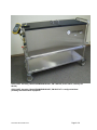
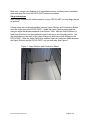
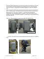
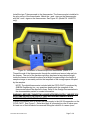
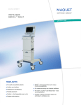
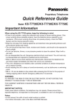
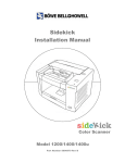
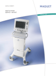
USER MANUAL
MVE CRYO CART
Model# FNLMVECRYOCART
MVE
CHART
BIOMEDICAL DIVISION
2200 Airport Industrial Drive, Ste 500
Ball Ground, GA 30107
Document#: W3170-Man Rev 3
Page 1 of 9
CRYO-CART Assembly, Model# FNLMVECRYOCART, PN 14448703 (shown above, formerly PN
W3170).
CRYO-CART Assembly, Model# FNLMVECRYOCART, PN W3170LT is configured without
plumbing and thermometer equipment.
Document#: W3170-Man Rev 3
Page 2 of 9
TABLE OF CONTENTS
TABLE OF CONTENTS .................................................................................................. 3
Receiving Inspection. ...................................................................................................... 4
Report Damage ............................................................................................................... 4
Components .................................................................................................................... 4
Handling Liquid Nitrogen ................................................................................................. 4
Setup Instructions............................................................................................................ 5
Normal Operating Procedures......................................................................................... 8
Questions / Parts ............................................................................................................. 9
Document#: W3170-Man Rev 3
Page 3 of 9
Receiving Inspection
When your new CRYO-CART arrives, unpack and inspect your CRYO-CART.
1. Visually inspect the packaging.
2. Take the cart out of the packaging.
3. Look for hidden damage and inventory the shipment.
Report Damage
In the rare instance that you find damage, report it immediately to the carrier. Report
any missing parts to Chart, Inc. or your Chart distributor.
Components
1.
Packet
Packet contents:
2.
a.
User Manual
b.
Limited Warranty Statement
c.
Thank You / Warranty Activation Card
d.
Liquid Nitrogen Container and Handling Instruction Guide
Thermometer box (for model PN 14448703 only)
Box Contents
a.
Omega HH507R Digital Thermometer (w/2 type K Thermocouples)
b.
Type T Thermocouple
c.
CD of software for Thermometer
d.
Users Guide for HH507R Digital Thermometer
e.
RS232 -Interface Cable
f.
Certificate of Calibration for the Omega Digital Thermometer
g.
9-volt Battery
3.
Transfer hose (for model PN 14448703 only)
4.
Vapor Platform
5.
Conduction Sheet(s)
Handling Liquid Nitrogen
Take Precautions when you use liquid nitrogen. Treat liquid nitrogen the same way you
would treat boiling water. Direct contact with liquid nitrogen may cause burns and freeze
your skin. Good handling of cryogenic samples dictates that you should always wear
gloves and eye protection.
Document#: W3170-Man Rev 3
Page 4 of 9
More over, nitrogen can displace air in unventilated rooms, so always use a ventilated
room and keep the lid on the CRYO-CART whenever possible.
Setup Instructions
After having completed the initial inspection of your CRYO-CART you may begin the set
up process.
If these items are not already installed, remove Vapor Platform and Conduction Sheets
from the under side of the CRYO-CART. Install the Vapor Platform piping end first
using an angle that allows clearance of the Sensor Tube. After the Vapor Platform is
lower than this tube it can be inserted the rest of the way in a horizontal position. Use
the slotted holes in the ends of the Vapor Platform to hold on to while sliding into the
CRYO-CART. After the Vapor Platform is installed, insert a Conduction Sheet between
the Vapor Platform and the CRYO-CART, one on each side. See Figure 1.
Figure 1- Vapor Platform and Conduction Sheet
Document#: W3170-Man Rev 3
Page 5 of 9
Attach the Digital Thermometer to the mounting bracket on the shelf end of the cart.
Open the jaws of the Mounting Bracket by pressing the button on the right hand
side. See Figure 2a. Thermometer and bracket supplied on model PN 14448703
only.
After inserting the Thermometer, press the bracket sides towards the Thermometer
until it is firmly in place. The Ball and Socket connection located on the Mounting
Bracket allows for a full range of positions. Loosen this joint and rotate the
Thermometer until the desired position is obtained. HAND TIGHTEN the nuts to
maintain the position. Periodically check this to unsure that it is not loosened during
use. See Figure 2b.
Figure 2a - Mounting Bracket (supplied with model PN 14448703 only)
Opening Mechanism
Figure 2b - Mounted Thermometer and Adjustment Socket (Model PN 14448703
only)
Document#: W3170-Man Rev 3
Page 6 of 9
Install the type T thermocouple to the thermometer. The thermocouple is installed in
the plug on top of the thermometer. Match the + and - signs on the thermocouple
with the + and - signs on the thermometer. See Figure 2c, (Model PN 14448703
only).
Figure 2c - Installation of thermocouple into thermometer (match +/-)
Thread the end of the thermocouple through the outside end sensor tube and into
the freezer. The end of the thermocouple may be placed at any desired height
inside the freezer but should be placed at a height corresponding to the height of
sample storage to accurately monitor the temperate of the storage space occupied
by the samples.
NOTE: The digital thermometer included with the CRYO-CART is produced by
OMEGA Engineering Inc.; any questions dealing with the operation of the
thermometer should be directed to them. Refer to the Omega Documentation in
the documentation packet for contact information.
WARNING: BEFORE CONNECTING LIQUID NITROGEN SUPPLY, INSURE YOU
ARE FAMILIAR WITH THE SAFETY PRECAUTIONS NECESSARY WHEN
WORKING WITH CRYOGENIC LIQUIDS!!
Connect the transfer hose of a liquid nitrogen supply to the LN2 fill connection on the
CRYO-CART. See Figure 3. Once the supply is connected turn the fill valve open.
At least one of the lids should be removed during the initial fill of a warm (room
Document#: W3170-Man Rev 3
Page 7 of 9
temperature) cart. Fill the container to the top of the vapor platform. Once the
desired liquid level is reached the valve should be returned to the off position. The
off position for the valve handle is perpendicular (90 degrees) to the flow path
through the valve. The on position for the valve handle is parallel to the flow path
through the valve. FOR LIQUID NITROGEN USE ONLY!
Figure 3: End view diagram of CRYO-CART (model PN 14448703 shown below)
Fill Valve
Handle
NOTE:
Valve is in the
OPEN
position
LN2 Fill
Connection
Normal Operating Procedures
LIDS
Insure that both lids are kept on the CRYO-CART when you are not using it.
Lids should only be removed when working with samples or when removing or
adding samples to the Cart. Keeping the lids on the Cart will ensure coldest
possible storage space and maximize liquid hold time.
At least one of the lids should be removed when filling a warm (room temperature)
Cart.
Document#: W3170-Man Rev 3
Page 8 of 9
WARNING: BOTH LIDS ARE TO BE IN PLACE ANY TIME WHEN THE CRYOCART IS BEING MOVED WITH LIQUID NITROGEN IN IT! FAILURE TO HAVE
THE LIDS PROPERLY IN PLACE MAY RESULT IN LIQUID NITROGEN
SPLASHING OUT OF THE CART!
Liquid Level
The CRYO-CART is designed to have a maximum liquid level that is equal to the top
of the working surface of the vapor platform. This liquid level should be refilled when
the thermometer indicates that the current temperature in the cart is approaching the
maximum (warmest) temperature you desire.
Questions / Parts
For questions or replacement parts, please contact:
USA:
Chart Biomedical
2200 Airport Industrial Drive, Ste 500
Ball Ground, GA 30107
PH: 1-800-482-2473
FX: 1-888-932-2473
Europe/Middle East:
Chart Biomedical Ltd
Unit 2, Maxdata Centre
Downmill Rd
Bracknell
Berks RG12 1QS
United Kingdom
PH: 44 (0) 1344 403100
FX: 44 (0) 1344 429224
Asia/Australia/Pacific Rim:
Chart Australia Pty Ltd.
ABN 21 075 909 410
Sydney Business & Technology Centre
Unit 43 / 2 Railway Parade
Lidcombe NSW 2141 Australia
PH: 612-974-94-333
FX: 612-974-94-666
Document#: W3170-Man Rev 3
Page 9 of 9