1
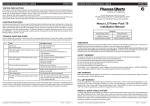
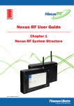
Complete Solutions in Emergency Lighting STANILITE
Complete Solutions in Emergency Lighting STANILITE
Doc No: 29-01068
TROUBLE SHOOTING GUIDE
If you’ve installed and connected the Power Pack as per the instructions listed earlier and it doesn’t work properly, use the following
table as a guide to fixing the problem. Look up the type of fault in the left column and check the possible causes from the right column.
#
Fault
Possible Causes
1
Red LED no lit
AC supply not connected; or
AC supply turned off; or
Battery plug not connected to battery pack; or
Test switch damaged
2
Red LED is lit but
AC lamp not lit when connected to mains
Switch active supply turned off; or
Missing loop from unswitched to switched active; or
Lamp damaged; or
Lamp not inserted properly
3
LED is lit but lamp doesn’t come on when test switch is
pressed
Lamp damaged; or
Lamp not inserted properly; or
Battery pack damaged; or
Test switch damaged
4
Lamp is lit momentarily when test switch is pressed; or
when mains fail
Thomas & Betts Australasia. ABN 062 074 810 898
Head Office: Unit D3, 3-29 Birnie Avenue, Lidcombe NSW 2141, Australia
Manufacturing: 23a Nyrang Street, Lidcombe NSW 2141, Australia
Telephone: (+61) 1300 666 595 Facsimile: (+61) 1300 666 594
Standard Power Packs
Installation Manual
Contents
Electrical Safety Warning
Installation Instructions
Power Pack Removal Method
Battery not fully charged (allow up to 24 hours); or
Battery pack damaged
Testing Precautions
If the unit still doesn’t work after checking these possible causes, contact Thomas & Betts Service in Australia on 1300 666 595, Monday
to Friday, 8.30am to 4.30pm (AEST) and ask for help. Our trained service personnel will usually be able to take your call immediately and
assist you in resolving your difficulty. Thomas & Betts is committed to providing valuable Through-Life Support for its products.
Trouble Shooting Guide
Warranty Information (Included)
GREETINGS
Congratulations on choosing to use this Thomas & Betts product covered by our unique Through-Life Support system. This document is
designed to assist you during the installation of the product, to ensure the safety of yourself and others.
The Power Packs are designed to be installed quickly and easily however, Thomas & Betts recommends that you read
this document thoroughly before commencing installation. This device has been manufactured to provide trouble free
operation for many years, when treated with due care and maintained through regular and appropriate servicing.
SAFETY WARNING
In Australia and New Zealand, only licensed electricians are permitted by law to work with 240 Volts electrical installations.
Do not attempt to install or connect this product unless you are a licensed electrician.
Turn off and isolate the electrical supply before connecting this fitting to the building wires.
Do not touch the terminals of the terminal block when the light fitting is powered.
The only user serviceable part is the battery pack.
Do not tamper with the fitting or the warranty will be void.
As the installer, it is your responsibility to ensure compliance with all relevant building and safety codes, (ie: AS3000, AS/NZS2293).
Refer to the applicable standards for mains cabling installation procedures and requirements.
EMC WARNING
Power Pack complies with EMC regulations. We advise that if you incorporate this pack into your product (batten / fitting) you must test
the complete (product / fitting) for EMC compliance.
© Copyright 2013. Thomas & Betts Australasia ABN: 062 074 810 898.
Rev: 4.0
15 April 2013
4
© Copyright 2013. Thomas & Betts Australasia ABN: 062 074 810 898.
Rev: 4.0
15 April 2013
1
Complete Solutions in Emergency Lighting STANILITE
Complete Solutions in Emergency Lighting INSTALLATION INSTRUCTIONS
1.
Remove the Power Pack from the packing box and inspect it for damage or imperfections. If any damage is found, do not install,
replace it carefully into the packing box and notify the Thomas & Betts Product Support Hotline in Australia on 1300 666 595.
2.
If all looks okay, proceed with the installation; use a pencil to mark the position of the mounting screw holes for the inverter and
battery pack in the gear tray. Figure 1 shows the inverter pack dimensions.
5.
Non-maintained Fitting: Once powered up, in a non-maintained fitting the present lamp stays off. The emergency function of the unit should only operate when the unswitched active power supply fails or when somebody presses the manual test button
located on the fitting. Normal status of the fitting when powered indicating LED steady red. This indicates that the power is
connected and the battery is charging.
STD Inverter Dimensions
42
225
6.
Figure 1: Inverter Pack Dimensions Fit the inverter and battery pack using suitably sized screws and nuts. Make sure that the battery pack is mounted away from the
ballast or from any other components that may get hot. Figure 2 shows a block diagram of how a Power Pack works.
LED Indicator
240 V
AC
Battery
Low
Voltage
Cut-off
Supply
Failure
Sensor
Normal to
Emergency
Change-over
Switch (optional)
4.
Before removing the installed Power Pack, switch off the mains supply to the fitting. Unscrew the unswitched active, switched active,
neutral and output (lamp and ballast) wire connections from the terminal block using suitably sized screwdriver. Undo the test switch nut
and remove LED from the grommet. Disconnect the battery plug from the battery pack and then unscrew the mounting screws of the
Power Pack. When the fitting is reconnected to the supply, it will need time to recharge its battery before it will be capable of a full length
discharge again.
Fluorescent
Tube
Choke
Note: When sending Power Packs for repairs make sure that LED and test switch are included with the Power Pack.
Figure 2: How a Power Pack works
TESTING PRECAUTIONS
Figure 3 shows wiring connections using Power Pack and conventional magnetic ballast.
If the fitting is to be left permanently connected to the mains supply from now on, you will need to allow 24 hours to charge its battery
and then you will have to conduct a manual discharge test as per the requirements of AS/NZS2293.2. Presently (at the time of writing),
the standard requires that the new light fittings operate in emergency mode for at least 2 hours for their first test. Subsequent tests are
required every 6 months; the light fittings are then required to operate for not less than 90 minutes. You will need to keep records of the
initial test into the building emergency service logbook.
If the fitting isn’t permanently connected to the mains supply at this time, you are responsible for giving it the initial 2 hour test when you
do connect it permanently to the mains supply.
The unswitched active wire connects to the terminal marked U/SA.
The switched active wire connects to the ballast as shown in the figure 3.
The neutral wire connects to the terminal marked neutral.
The earth wire connects to the earth lug and should be labelled with the earth label.
The lamp and ballast wire connections are as shown in the wiring diagram.
Ensure that the stripped wire ends are completely inserted into the terminal block and no bare conductors are exposed to the metal.
Black
Ballast
Lamp
Red
Neutral
LED
Standard Power Pack
CONSTRUCTION SITES
Continuously switching on and off the mains supply to the fittings during the installation process (due to building works or for some other
reason), could cause the fittings to discharge and charge their batteries many times over a short period which may shorten the life of the
battery. Thomas & Betts does not recommend such practices and may not honour any warranty on the life of the batteries or the lamp
when subjected to such harsh operating conditions. The fittings are designed to be regularly discharge tested once every 6 months as
per AS/NZS2293.2. In order to prevent damage to the battery, leave the unswitched active circuit turned off at the circuit breaker, until the
emergency lighting is required on the site.
240V AC 50Hz
S/A Neutral
Battery Pack
240V AC 50Hz
Unswitched Active
Check the operation of the fitting to ensure that the installation was successful. When powered up, allow a few minutes to give the
battery a small charge, then press the manual test button located on the fitting. Press and hold the test button for a few seconds
and observe that the emergency lamp lights up and stays on until the test switch is released. If the lamp works only momentarily,
this ensures that the connections are correct and the battery requires at least 16 hours to fully charge. If the lamp doesn’t work at
all, check the supply, the connections and the trouble shooting guide at the end of this document.
TO REMOVE THE POWER PACK FROM THE INSTALLATION
MCB
Battery
Charger
Lamp operation:
Maintained Fitting: Once powered up, in a maintained fitting the normal AC lamp (if present) should lights up and stays on until the power supply fails. The emergency function of the unit should only operate when the unswitched active power supply fails or when somebody presses the manual test button located on the fitting. Normal status of the fitting when powered indicating LED steady red. This indicates that the power is connected and the battery is charging.
42
3.
STANILITE
Note: Wiring connections are different if using electronic or other magnetic ballast. Wiring diagrams are available from
Thomas & Betts on request.
To install the Power Packs, follow these steps:
S
Test Switch
Figure 3: Wiring Diagram Standard Power Pack using conventional magnetic ballast
© Copyright 2013. Thomas & Betts Australasia ABN: 062 074 810 898.
Rev: 4.0
15 April 2013
2
© Copyright 2013. Thomas & Betts Australasia ABN: 062 074 810 898.
Rev: 4.0
15 April 2013
3