1
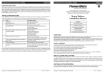
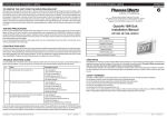
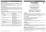
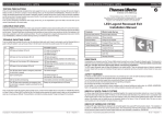
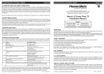
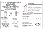
ISO 9001
Nexus RF User Guide
Chapter 4
AC Version 2 - User Interface Guide
Doc No: 29-00001 (Chapter 4)
Table of Contents
1. IntroductionPage 2 - 6
1.1 Sample AC PagesPage 2 - 4
1.2 Screen Saver ModePage 4
1.3 On-screen Keypad v’s USB Keyboard
Page 4
1.4 Backdoor ModePage 4
1.5 AC Indicator LED’sPage 5
1.6 AC DatabasePage 5
1.7 AC Standby ModePage 5
1.8 AC Start-up and ShutdownPage 5
1.9 The Main Menu OptionsPage 6
2. Status Menu OptionPage 7 - 8
3. Commission Menu OptionPage 9 - 12
3.1 Commission - Site TabPage 9
3.2 Commission - Router TabPage 10
3.3 Commission - Group TabPage 11
3.4 Commission - Unit TabPage 12
4. Test Menu OptionPage 13 - 15
4.1 Test - Status TabPage 13 - 14
4.2 Test - Schedule TabPage 15
5. Report Menu OptionPage 16 - 17
1
1. Introduction
The Area Controller (AC) is an essential part of every Nexus® RF emergency lighting system. The AC provides
the system user complete operational control of their Nexus RF system without the requirement of a dedicated
PC head-end. The AC incorporates a LCD touch screen interface through which an operator can access all of the
system’s configuration, monitoring and reporting functions.
Every Nexus RF system will have at least one AC and on larger installations several AC’s may be used. The
AC offers identical RF functionality as the Area Controller Routers (ACR’s) but in addition provides an operator
interface and optional battery backup. The battery backup enables the AC to be utilised in certain situations as a
mobile device for system diagnostic purposes.
The user interface provided by the AC is very intuitive and once an operator has a basic grasp on the main menu
options available it is generally easy to locate the general functions of the system. It is the aim of this chapter to
provide an operator with an overview of the available menu’s and configuration pages available from the AC.
1.1 Sample AC Pages
Below are some sample AC pages which highlight the various types of on-screen fields and touch screen modes of
navigation.
Function
Selection Tabs
Domain Name
System Date/Time
Mains
Connection
and Battery
Charge State
Main Menu
Options
Multi-Page
Navigation
List View
Display
2
Sub Menu
Functions
Left and Right List
View Scrolling
Configuration/
Status Parameters
3
Unit in Yellow Blink Mode
Unit Offline
Unit in Fault
Unit Under Test
Uncommissioned Unit
1.2 Screen Saver Mode
When an AC has no user activity for more than a period of X minutes the LCD display will go into screen saver
mode. To return the AC to normal operation, simply tap on the touch screen. This time period is a configurable
parameter under the battery management settings.
1.3 On-screen Keypad v’s USB Keyboard
The AC provides an on-screen keypad for general data entry. In situations where extensive amounts of data entry
are required, you may find the use of an externally connected USB keyboard to be a more efficient option.
1.4 Backdoor Mode
The AC provides the backdoor mode of operation, which allows an operator to go mobile with the AC and directly
interrogate and configure fittings. Some important points regarding the backdoor mode:
•
In this mode the AC is no longer trying to build an RF mesh, but is attempting to make a direct connection with
fittings located within its immediate area.
•
Communicating to a fitting via the AC’s backdoor mode does not impact the fittings ability to continue
communicating as part of another Routers RF Mesh.
•
The effective radius to which fittings can be detected from the AC can be adjusted by configuring the backdoor
threshold, the default being set to the most sensitive. A good all round value to start with is ~ -90dB.
•
If the AC under normal operation has its own RF Mesh, then enabling the AC’s backdoor mode will effectively
destroy this mesh for the duration that the AC is operating in this mode.
The backdoor mode is typically used in the following scenarios:
•
To assist in the identification of unidentified or unlabelled RF fittings.
•
To locate uncommissioned fittings in the system.
•
To reconfigure a units system ID to match that of the sites system ID.
4
1.5 AC Indicator LED’s
The AC has four LED indicators that represent the units power, EIM and battery
module status.
LED Name
LED Description
AUX
Off - This LED is currently unused
EM2
On - Battery module is installed and operational
Off - No battery module
EM1
On - RF EIM is installed and operational (occasionally flashing off to
indicate RF communications)
Off - No RF EIM
PWR
On - System is running under either mains or battery power
Off - System is not running (may be still connected to mains but in standby
mode)
1.6 AC Database
Each of the AC or ACR Controllers in the system maintains their own copy of the database that is continuously
synchronised with the databases of the other site Controllers. Persistent storage of the database is provided by an
internally mounted SD card. During Router start-up the database is read from the SD card into the Routers RAM.
The database continues to run from the Routers RAM, which periodical writes of the RAM database back to the SD
card.
1.7 AC Standby Mode
The AC provides a standby mode of operation, intended for use when the Controller is being used in mobile mode
under battery power. This is a reduced power mode that assists in conserving the Routers battery during periods
of non-usage, whilst out in the field. The AC’s standby mode can be activated by a short press of the units on/off
button. Normal mode operation can be restored by again pressing the AC’s on/off button or connecting the unit to
mains power.
1.8 AC Start-up and Shutdown
The AC can be started by the following methods:
•
Apply mains power or disconnect and reconnect mains power.
•
If the AC is in standby mode, press the on/off button to start the AC under battery power.
•
If the AC is shutdown, press and release the button on the battery module.
The AC can be completely shutdown by pressing and holding the on/off button for 3 seconds.
5
1.9 The Main Menu Options
The Main Menu options are available from all pages and provide a rapid means for navigating between the
different modes of system functionality. The functionality of each of the Main Menu options is as follows:
6
Menu Option
System Functions
Status
Displays the Status page, which provides an overall summary of the
current system state
Commission
Displays the Commission page, which provides tools for the configuration
of the site, Routers, groups and units
Test
Displays the Testing page, which provides tools to view and edit group
and scheduled testing information
Report
Displays the Reporting page, which gives the user access to the available
system reports
Back
Reverts the display back to the previous page
2. Status Menu Option
When the AC is switched on and boots up, the systems Status page is displayed. This page provides an overall
summary of the current system state and access to the Main Menu options. Each of the status fields are on screen
links to an array/list view display of the relevant data, eg: selecting the Total status field link will result in an array
view of all of the units in the system.
Array view of all
units in the system
7
List view of all incomplete
units in the system
8
3. Commission Menu Option
The Commission menu option provides tools for the configuration of the site, Routers, groups and units. The
following sections detail the functions available under each of the site, Router, group and unit function selection
tabs.
3.1 Commission - Site Tab
Page Description
Provides site related commissioning and control functionality.
Page Item Function
9
Page Item Selected
Action/Function
Set site name
Provides functions to edit the site name, the domain and site address
Set date and time
Provides functions to set the system date, time and timezone
Units yellow blinking on
All units in the domain will go into the yellow blink mode
Units yellow blinking off
All units in the domain will have the yellow blink mode cancelled
Firmware update
Reserved for Thomas & Betts service representatives
3.2 Commission - Router Tab
Page Description
Provides Router related commissioning and deletion functionality.
Page Item Function
Page Item Selected
Action/Function
Change my Router details
Provides functions to edit the AC’s ID, name, system ID and IP address
configuration
Change my Router location
Provides functions to edit the AC’s location parameters, ie: building,
position, floor, etc
Add neighbour Routers
Provides functions to add additional AC or ACR Routers to the system
Delete Routers
Provides a mechanism to delete Routers from the system
Power management
Reserved for Thomas & Betts service representatives
Firmware versions
Reserved for Thomas & Betts service representatives
10
3.3 Commission - Group Tab
Page Description
Provides user defined group related adding, deleting and editing functionality.
Page Item Function
Page Item Selected
Action/Function
Add new group
Provides a mechanism for adding additional user defined groups onto the
system
Delete group
Provides a mechanism to delete user defined groups from the system
Rename group
Provides a mechanism for renaming user defined groups
11
3.4 Commission - Unit Tab
Page Description
Provides unit related commissioning and deletion functionality.
Page Item Function
Page Item Selected
Action/Function
Get commission data
Dumps a commission data report to a USB Drive
Delete units
Provides a mechanism to delete units from the system
Mobile commissioning
Puts the AC into backdoor mode
Spreadsheet commissioning
Used to upload a commissioning spreadsheet into the AC from a USB
drive
12
4. Test Menu Option
The Test menu option provides tools for the following group related functions:
•
Viewing group fitting assignment.
•
Viewing group test scheduling.
•
Scheduling group tests.
•
Stopping a group scheduled test.
•
Deleting group scheduled tests.
•
Access to specific group tools for adding or removing fittings to or from a group.
The following sections detail the functions available under each of the status and schedule function selection tabs.
4.1 Test - Status Tab
Page Description
Displays the systems groups and their associated fittings and scheduled test dates.
Page Item Function
Clicking on a groups
icon results in the Group page being displayed for this group.
Group Page
The Group page has two function selection tabs, these being units and group tools. The units function tab,
provides an array view of the units that are currently allocated to this group. The group tools function tab provides
functions for the adding or removal of units to or from the group and functions to yellow blink the fittings belonging
to the group.
13
Array view of units
belonging to Group 0
14
4.2 Test - Schedule Tab
Page Description
Provides group related functionality related to scheduling tests; stopping tests and deleting scheduled tests.
Page Item Function
Page Item Selected
Action/Function
Program schedule
Provides a mechanism to schedule a discharge test for multiple groups
Stop schedule
Provides a mechanism to stop active group schedule tests
Delete schedule
Provides a mechanism to delete scheduled group test dates
15
5. Report Menu Option
The Report menu option provides access to the many reports provided by the system. The reports have been
categorised into three main sections, these being:
•
Test Result Reports
•
Work Instruction Reports
•
Maintenance Log Reports
On selecting one of the report options, the user will be requested to enter a USB drive into the AC. The report is
then written as a text file to the USB drive under the reports subdirectory.
16
17
Blank Page
18
Blank Page
© Thomas & Betts
(Australasia) Pty. Ltd. 2014
All technical claims in this document are based upon technical information available at the time
of publication. This information may change over time and comparisons may therefore vary.
Thomas & Betts (Australasia) Pty. Ltd. ABN 62 074 810 898
Head Office: Unit D3, 3-29 Birnie Avenue, Lidcombe NSW 2141, Australia
Manufacturing: 23a Nyrang Street, Lidcombe NSW 2141, Australia
Phone: 1300 666 595 │ Fax: 1300 666 594 │ Email: [email protected] │ Website: www.tnbaust.com
Rev: 1.0
14 October 2014