1
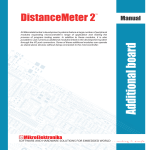
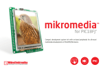
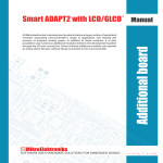
All MikroElektronika´s development systems represent irreplaceable
tools for programming and developing microcontroller-based devices.
Carefully chosen components and the use of machines of the last
generation for mounting and testing thereof are the best guarantee of
high reliability of our devices. Due to simple design, a large number of
add-on modules and ready to use examples, all our users, regardless
of their experience, have the possibility to develop their projects in a
fast and efficient way.
Manual
Development System
SmartG100
™
MikroElektronika
SmartG100
SmartG100 is a full-featured development tool for the uBlox Leon-G100 GSM/GPRS module. This board has everything
you need to create your own GSM-GPRS-based device.
Key features:
- Data transfer via uBlox Leon-G100 module;
- Microphone and speaker connectors;
- UART communication with microcontroller;
- 7-23V AC or 9-32V DC power supply voltage.
Figure 1: SmartG100 with uBlox Leon-G100 module
MikroElektronika
How to connect the board?
The SmartG100 is designed for use with Mikroelektronika’s development systems. To make connection between
development system and SmartG100 use flat cable with IDC10 connector and make connection between 2x5 male
header on development system port and 2x5 male header CN1 on SmartG100. Which port on development system will
be used depends on position of MCU pins which are used for UART communication. When connection is established,
depending which development system is in use, turn ON appropriate switch on DIP switch SW1, Table 1.
Development system
SmartGM862 CN1 pin
UART pin
PIC/PIC18FJ
PIN7
RX
dsPIC30/33/PIC24
PIN4
RX
AVR/8051
PIN0
RX
ARM
PIN1
RX
PIC/PIC18FJ
PIN6
TX
dsPIC30/33/PIC24
PIN5
TX
AVR/8051
PIN1
TX
ARM
PIN0
TX
Table 1: DIP switch SW1 position
In order to supply SmartG100 with power it is necessary to connect external power supply via AC/DC connector
CN1. Power supply voltage can be in range between 7 to 23V AC or 9 to 32V DC. As indication that power supply is
connected LED marked with POWER will be turned on. To connect microphone with SmartG100 use screw terminal
CN4 which is marked with MIC. On “GND” side of screw terminal connect minus phase, and on “IN” side connect plus
phase of the microphone. In order to connect speaker use screw terminal CN5 marked with SPEAKER. “-” side of screw
terminal is used for minus phase and “+” is used for plus phase of speaker. If you want to access Leon-G100 module
pins on SmartG100 board you can use marked pads CN6. To power up Leon-G100 module is necessary to press and
hold push button marked with “POWER ON GSM MODULE” for 1s.
How to use the board?
In order to use SmartG100 connect antenna with Leon-G100 module, Figure 1. Connect power supply via AC/DC
connector and now connect SmartG100 with development system as described in previous section. Write program and
upload it to MCU on development system. Program example can be found on:
http://www.mikroe.com/eng/products/view/526/smartg100-board/
MikroElektronika
AC/DC power supply
connector CN1
Marked pads CN6 are used
for accessing Leon-G100
module pins
2x5 male header is
used for connection with
development system
uBlox Leon-G100 GSM/
GPRS module
To power on Leon-G100
module press and hold
push button for 1s
DIP switch SW1 is used
to select RX and TX pins,
Table1
SIM Card holder
GSM anttena screw
Figure 2: SmartG100
Figure 3: SmartG100 dimensions
MikroElektronika
Figure 4: SmartG100 connection schematics
MikroElektronika
If you have any questions, comments or business proposals, do not hesitate to contact us at [email protected]
If you are experiencing some problems with any of our products or just need additional information, please place your ticket at
www.mikroe.com/en/support
If you want to learn more about our products, please visit our website at www.mikroe.com