1
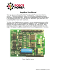
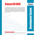
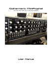
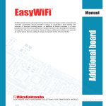
All Mikroelektronika’s development systems feature a large number of peripheral
modules expanding microcontroller’s range of application and making the
process of program testing easier. In addition to these modules, it is also
possible to use numerous additional modules linked to the development system
through the I/O port connectors. Some of these additional modules can operate
as stand-alone devices without being connected to the microcontroller.
Manual
Additional board
DistanceMeter 2
™
MikroElektronika
DistanceMeter 2
The DistanceMeter 2 additional board is used to measure distance by using ultrasonic waves.
Key features:
- Sound Pressure Level (SPL): 117dB (0dB=0.2n bar);
- Sensitivity (SEN): -60dB (0dB 1V/u bar);
- Operating Frequency: 38KHz to 42KHz;
- 3.3V or 5V power supply voltage.
Figure 1: DistanceMeter 2 additional board
How to connect the board?
The DistanceMeter 2 is connected to a development system via IDC10 connectors CN1 and CN2. Depending on the
development system in use, it is necessary to set the appropriate switch on DIP switch SW1 to the ON position.
How to use the board?
The operation of the DistanceMeter 2 board is based on sending and receiving ultrasonic waves. Ultrasonic waves are
sent by using transducer UT1 and received by using transducer UT2. Time between sending an ultrasonic wave and
receiving reflected one determines the distance of an object.
UT1 transmits ultrasonic waves when appropriate signals are brought to PWMA and PWMB lines. The frequency of
these signals should range between 38 and 42KHz and they may be generated via PWM module’s pins or I/O pins of
a microcontroller. DIP switch SW1 is used to select which two microcontroller pins will be used for this (see Figure 2).
When an ultrasonic wave is sent, time measurement should start.
UT2 receives transmitted ultrasonic waves after they are reflected by an obstacle, wall for example. Received wave is
converted by UT2 into an electrical signal which is then amplified and sent to an analog pin of A/D converter built into
the microcontroller. DIP switch SW1 is used to select which microcontroller analog pin will be used for this (see Figure
2). When microcontroller receives a signal via this pin, time measurement is done and if voltage is higher than some
predefined voltage threshold, measurement is valid (signal is not caused by some noise). Measured time can now be
used to calculate the distance. When doing calculation, it should be taken into consideration that the wave passes
two distances (to the obstacle and back), so the time needs to be divided by two and then multiplied by the speed of
sound.
Concrete example on how to measure distance using DistanceMeter 2, can be found on our website at
www.mikroe.com
MikroElektronika
Figure 2: DistanceMeter 2 additional board connection schematic
Figure 3: Dimensions of the DistanceMeter 2 additional board
MikroElektronika
MikroElektronika
If you have any questions, comments or business proposals, do not hesitate to contact us at [email protected]
If you are experiencing some problems with any of our products or just need additional information, please place your ticket at
www.mikroe.com/en/support
If you want to learn more about our products, please visit our website at www.mikroe.com