1
Utah Robotic Kit
Operating & Design Manual
With Intersecting Two Degree Wrist
Jason Stulp
Candidate for Master’s of Engineering
Advisor: Dr. Sanford Meek
Mechanical Engineering
University of Utah
July 1st 2003
Table Of Contents
TABLE OF CONTENTS ................................................................................... 2
BACKGROUND .................................................................................................................. 3
SYSTEM OVERVIEW ......................................................................................................... 4
MECHANICAL DESIGN ................................................................................. 5
POSITION SENSING ........................................................................................................... 6
Potentiometers ............................................................................................................ 6
Encoders ..................................................................................................................... 8
MOTORS......................................................................................................................... 11
POWER SUPPLY / AMPLIFIER .......................................................................................... 12
Power Supply and Amplifier Wiring Diagram.......................................................... 14
Pulse Width Modulator ............................................................................................. 15
DSPACE CONTROLS ...................................................................................... 17
SOFTWARE BREAKDOWN / OVERVIEW ........................................................................... 18
ANGLES CALCULATIONS ................................................................................................ 20
Gain Block Example ................................................................................................. 20
CARTESIAN COORDINATES (INVERSE KINEMATICS): ..................................................... 20
Workspace Variable Example: ................................................................................. 21
S-Function Example: ................................................................................................ 22
GRAVITY COMPENSATION.............................................................................................. 25
Symbolic Math Example: .......................................................................................... 26
CONTROL DESK .............................................................................................................. 27
ROBOTICS TOOLBOX .................................................................................. 28
JASON’S LOGO MAKER ............................................................................. 30
TABLE OF FIGURES....................................................................................... 31
APPENDIX ............................................................................................................... 33
ENCODER MOUNTING PLATE ......................................................................................... 33
URK CONTROL DESK LAYOUT [URK.LAY].................................................................... 34
URK SIMULINK MODEL [URK.MDL].............................................................................. 34
2
Table of Contents
URK/Robotics Manual
Background
The URK (Utah Robotics Kit) was created with the purpose of being an instructional
robot. With this in mind, the design and operation is relatively straightforward and
simple. This paper is comprised of general information and resources, as well as, specific
supplemental information that is added to benefit the user. Examples and drawings were
created as a quick easy reference for general sensors along with pertinent aspects of the
URK. Detailed schematics or diagrams of hardware that are included were done for
documentation purposes.
This Operating & Design Manual is not intended for use as a sole resource, but an aid in
equipping the user with information and documentation to overview the design and
utilization of the URK. It is recommended to use the following sources for in-depth
information:
J.J. Craig, Introduction to Robotics, 2nd ed., Addison-Wesley Publishing Company, 1989
M.W. Spong & M. Vidyasagar, Robot Dynamics and Control, John Wiley & Sons, 1989
Websites:
MATLAB: www.mathworks.com/products/matlab
Simulink: www.mathworks.com/products/simulink
DSPACE: www.dspaceinc.com
Robotic Toolbox: www.cat.csiro.au/cmst/staff/pic/robot
URK Project: www.eng.utah.edu/~stulp
Figure 1: URK
3
Background
URK/Robotics Manual
System Overview
URK/Robotics Manual
System Overview
The figure on the right is
composed of the system
setup.
Each component
will be discussed in more
detail later in this manual.
Interface
The flow begins with a
computer program for the
robot, which is uploaded to
the control board.
The
control board runs in real
time and communicates
requested information to
the computer. The output
signal from the board is
amplified to the motors on
the robotic arm. The
position of the arm is
determined by the signal of
a potentiometer or encoder
on the specific joint that is
input back to the control
board to recalculate the
output to the motors.
dSPACE Control Board
Power Supply
& Amplifier
Motors
θ
θ
θ
θ
Potentiometers
/ Encoders
θ
Figure 2: System Flow
4
URK/Robotics Manual
The URK is an articulated robot arm consisting of three revolute joints (RRR). For this
paper it has been configured with a two degree intersecting wrist to give it a total of five
degrees of freedom.
For ease of geometry, the wrist is designed with an offset that allows the calculation of
position to be simplified by having all the joints residing in the same plane.
The following figure shows the joint name assignments. Thetas/DOFs 2 through 4 are all
located in a plane that rotates about theta/DOF 1. The dashed lines represent axes of
rotation.
z
θ1
y
x
θ3
θ2
θ5
θ4
Figure 3: URK’s Degrees of Freedom
Figure 4: URK Picture
5
Mechanical Design
Mechanical Design
URK/Robotics Manual
Position Sensing
There are two different types of sensors to determine position of the robot, potentiometers
and encoders. The URK uses both.
Potentiometers, or pots, translate the position angle between the two links into voltage.
The URK uses a single turn wire wound/resistor pot. The pot has three connections, as
shown in figure 5 by the standard schematic.
Figure 5: Connection Schematic
Figure 6: Pot Assembly
The recommended setup for the connections uses a ±5 volt power supply. Typical pots
use ground and a specific voltage. Turning the pot, proportionally gives a voltage inbetween –5 and +5. In the URK’s case, it is easer to use ±5 volt connections, making the
center of the range zero volts. This simplifies relating the angle in degrees as positive or
negative.
Link 2
Link 1
Link 1
Link 2
Pot Location
Pot Location
Wound/Resistor
-5V
-1V
+5V
-5V
0V
+1V
0V
+5V
Armature/Wiper
Figure 7: How a Pot Works
6
Potentiometers
Potentiometers
URK/Robotics Manual
The pots on the URK in the figure below are manufactured by Spectrol, which are no
longer available. Vishay Inc. acquired Spectrol in 2000, having similar potentiometers
but not an exact match. There are rebuild kits available that consist of new wound/resistor
and armature rather than fully replacing the entire assembly.
The easiest way to adjust the pots, or ‘trim’ them, is to loosen the three setscrews on the
casing and rotate the pot to the desired position.
1 of 3
Setscrews
Spectrol
Potentiometer
Figure 8: URK’s DOF #3
7
Potentiometers
When using pots, there are a few considerations to point out. A pot will give the angle
immediately when turned on requiring no indexing or homing. There is no need to adjust
them once they are set. The major concern with pots is noise. With the armature sliding
across the wound/resistor, the signal results in spikes. Noisy power supplies as well as
unshielded wire (environment noise) also distort the signal contributing to the problem.
URK/Robotics Manual
Encoders
There are two types of encoders, incremental and absolute.
Absolute encoders consist of a disc that has individual rows that give a unique output
code. They are similar to pots by having the advantage of giving the position without any
calibration. The disadvantage is that they are typically more expensive than incremental,
less resolution, and have many more connections on the robot.
Encoders
28 = 256 steps / revolution
360/256 = 1.4° precision
10 wire connections
Figure 9: 8-bit Absolute Encoder Disc
Incremental Encoders are more simple, having only three rows of information; A, B, and
Index. It operates by using a quadrature format, where B is 90° out of phase from A.
¼ ½ ¾ 1
Increments
A
B
Index
Figure 10: Incremental Encoder Signal
Having both an A & B channel, the direction of rotation is determined. Using the
quadrature format a step is then divided into quarter steps. The incremental encoder for
the URK consists 500 increments, giving it a actual resolution of 2000 steps. The index
gives a home position since, unlike absolute, incremental encoders are unable to know
their true position until the index is found. In the URK’s case, when power is supplied to
the encoders it starts at zero.
8
URK/Robotics Manual
Index (Home Position)
500 steps / revolution
360/(500*4) = .18° precision
5 wire connections
Encoders
Figure 11: Incremental Encoder Disc
Figure 12: Encoder Mounted on Wrist
Figure 13: Incremental Encoder Exposed
Figure 14: URK’s Encoder Pin-out
Figure 12 shows an incremental encoder mounted on the wrist. The model of encoder
shown (BEI) has been discontinued. A similar encoder is the HEDS 5540. The
mounting plate is design to accept both encoders.
9
URK/Robotics Manual
Either pots or encoders can be used on the URK. Below is a chart summarizing ‘pros’
and ‘cons’ of each sensor.
Position Sensor Comparison Summary
Potentiometer
Absolute Encoder
Incremental
Encoder
Startup / Power loss
Recovers
Recovers
Has to be homed
Interference
Very Noisy
Very low noise
Very low noise
Cost
Low cost $
Higher than
Incremental $$$
Intermediate $$
Resolution
Limited
Typically Less than
Incremental
Must be counted in
software
Power
Requires Power
Source
Can operate off of
controller power
Can operate off of
controller power
Encoders
Issue
Figure 15: Position Sensor Comparisons Table
The recommended sensor of the URK is the incremental encoder. With its resistance to
noise, power provided through the dSPACE control board connection, and imbedded
counter, it is the best choice as long as an efficient and safe way to find the index is used.
A mount design that fits both HEDS and BEI encoders is attached in the Appendix.
dSPACE has blocks that help create search algorithms to find the index. Besides coding
a homing program, there are two easy ways to find the index. The first is the manually
rotate the index by loosening the setscrew and rotating the disc to approximately the same
location of start-up. The index will not be far and will reset once the robot moves with
out a lot of ‘jerk’. The second recommended ways is the leave the motors off when the
controller is turned on and manually move the robot until the indexes are found. The
motors can then be turned on with out a jerking motion.
10
URK/Robotics Manual
Motors
The motor’s mounting design is straightforward and is not discussed in-depth. The
overall design of the robot allows a motor to be replaced quickly and easily without
having to count teeth on the sprocket or belt. This setup allows position control even
with the belt stretching, since it is all determined from the joint as opposed to attaching
the encoder or potentiometer directly to the motor. The position read from the motor,
which is commonly done, allows the sensor to go through the same gear reduction as the
motor. This potentially increases resolution as well as guaranteeing stability. Most
motors sold today have an available complete kit, having an encoder mounted directly on
it.
Figure 16: Motor Drive DOF #2
Optional location for
Encoder
11
Motors
The motors used to put URK into motion are all DC motors with brushes. The motors
currently used do not have specifications available for the specific model in use.
Brushless or AC motors should not be used unless the power amplifiers are changed.
Joints 1 & 2 use the same motor with different gearing. Joints 3, 4, & 5 consist of smaller
motors with attached gear reducers supplied by the manufacturer.
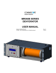
URK/Robotics Manual
Power Supply / Amplifier
Power Supply / Amplifier
To operate the motors there needs to be a power supply and amplifier. Below is the box
created for use with the URK. It consists of six individual amplifiers, allowing control of
six individual degrees of freedom. The figure below gives the output of the box. (The
right side of the power box is not specifically discussed. It can be and has been
configured for other projects and equipment beside URK.) Channels 5 & 6 do not have
connections installed for 5, +/-12, and 24 volt applications. This is because channels 5 &
6 share the same power supply, so it would be the last choice for drawing additional
voltage connections.
Figure 17: Power/Amp Box
+5V
+12V
-12V
+24V
Front Panel
Female BNC
GND
+ Motor
- Motor
+V Ref
-V Ref
1
2
3
4
5
6
Channels
Figure 18: Box Front Panel Labeling
12
URK/Robotics Manual
PWM Amp
Power Supply
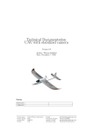
Figure 19: Individual Rack
The figure below consists of a top view layout of the racks. All of the wiring (not shown)
connects to a Din Rail on the left side and then runs to the connections on the front panel.
Connector Rail
Rack 1
Rack 2
Rack 3
Rack 4
Rack 5
Front Panel
Figure 20: Power Box Layout
13
Power Supply / Amplifier
The box consists of racks that slide
out vertically with individual power
supplies and Pulse Width Modulator
Amplifiers. PWM will be discussed
in a later section.
URK/Robotics Manual
Power Supply and Amplifier Wiring Diagram
+12V
-12V
+5V
+24V
GND
1 2 3 4 5 6
1 2 3 4
DC Output
Power Supply / Amplifier
Hitachi Power Supply
CS-8120 8-5503
AC Input
Advanced
1
2
3
4
5
Test / Offset
Vel Integrator
Curr Integrator
Voltage Feedback
Motion Controls
Brush Type
PWM Servo
Amplifier
White
N/C
Black
4
3
2
1
*See page #
+ Ref IN 4
- Ref IN 5
- Motor
+ Motor
Power GND
Power GND
High Voltage
1
2
3
4
5
Front Panel of Box
Figure 21: Power Supply and Amplifier Wiring Diagram
14
URK/Robotics Manual
Pulse Width Modulator
The amplifier is Pulse Width Modulator Servo Amplifier. Rather than outputting the
voltage from 0 to 24 volt DC it puts out a pulse of 24 volts and modulates the width of
the pulse.
+24 V
= 20 V
0V
Power Supply / Amplifier
+24 V
= 12 V
0V
+24 V
=4V
0V
Period
Figure 23: PWM Signal Example
The frequency is fast enough that the motor and averaging multi-meters see the
equivalent voltage. This design allows the amplifier to be more consistent, since the
design is only for 24 volts rather than an infinite range. The PWM Amplifier has its own
feedback control loop to sustain its output despite the moving arm creating huge current
changes.
The recommended settings for the Dipswitch are as follows:
Test / Offset
Vel Integrator
Curr Integrator
Voltage Feedback
4
3
2
1
On
Figure 24: Dipswitch Recommended Setting
15
URK/Robotics Manual
There are also 4 multi-turn potentiometers for calibration and adjustment.
Multiple
Turn Pots
Figure 25: Picture of Amp’s Pots & Dipswitch
Each amplifier should be calibrated and balance with each other.
recommended calibration order:
Here is the
PWM Amp Calibration
Order
Item
First
Dip Switches
Second
Adjust Offset Pot
Third
Ref In Gain Pot
Fourth
Loop Gain Pot
How to Calibrate
See figure 25
Jump +V ref and –V ref,
Read voltage between
+Motor & -Motor
Jump +V ref and –V ref,
Read voltage between
+Motor & -Motor
Jump +V ref and –V ref,
Read voltage between
+Motor & -Motor
Desired Calibration
See figure 24
Set to zero
Set to zero
Set to 2.5
Or the same for all
Channels
Figure 26: PWM Amp Calibration Table
This allows the motors to all operate the same on each channel otherwise each channel
has to be assigned to a specific part of the robot. Having an offset voltage can result in
noise generation within the motor. (This is similar to the tone heard for cordless drills at
low speeds.)
16
Power Supply / Amplifier
Dipswitch
URK/Robotics Manual
dSPACE Controls
Figure 27: dSPACE Logo
The center of control is the dSPACE control board model DS1103. The following
information is a quick overview of control ideas, methods and hints that were used in the
past project with straightforward position control.
The first step is starting up MATLAB, which will load dSPACE programs. In order to do
this, MATLAB, Simulink, Real-time Interface, and Control Desktop have to be installed
with access to licenses either on the computer or via the network.
dSPACE
Starting MATLAB will load everything except for Control Desktop. The following
figure is a screen shot of everything properly loaded at startup. The parameters should
also be noted, the start time is zero and end time for simulation is infinity.
Figure 28: Initial Loading Screen in MATLAB
17
URK/Robotics Manual
Software Breakdown / Overview
MATLAB
Simulink
Real-Time Interface
Control Desktop
Manufacture’s Description
“MATLAB is an intuitive
language and a technical
computing environment. It
provides core mathematics and
advanced graphical tools for data
analysis, visualization, and
algorithm and application
development. With more than
600 mathematical, statistical, and
engineering functions, engineers
and scientists rely on the
MATLAB environment for their
technical computing needs.”
“Simulink is a simulation and
prototyping environment for
modeling, simulating, and
analyzing real-world, dynamic
systems. Simulink provides a
block diagram interface that is
built on the core MATLAB
numeric, graphics, and
programming functionality.”
One of over 300 third party
products completely compatible
with MATLAB and Simulink.
Automatic implementation of
Simulink block diagrams and
State-flow state diagrams on
dSPACE hardware.
Virtual control panel for Realtime Interface.
Specific to URK
Generates path code and
computational models, as
well as, running specific
toolboxes.
Uses analog computer
symbolic language to create
control programming
Compiles Simulink model
into C and runs on the
dSPACE board to real
world operation. It’s the
same little box in the corner
of the Simulink model.
Allows the creation of
gauges, switches, and a user
friendly interface with the
controller.
Figure 29: Software Overview Table
18
dSPACE
Software
URK/Robotics Manual
It is highly recommended that the tutorials and help sections of all the software be
explored. This manual points out a few things that help expedite the implementation and
operation by giving partial examples of multiple methods of quickly taking the
calculations and equations into controlling the robot.
The first step is setting up the controller with a simple loop in Simulink:
Classic Loop Diagram:
Desired
Error
+
Actual
DAC (Robot) ADC
-
Figure 30: Classic Control Loop
Rearranged for Simulink:
ADC
(Robot)
dSPACE
Actual
Error
-
DAC
(Robot)
+
Desired
Figure 31: Robot Control Loop in Simulink
The actual position loop model for joint 1,2, & 3 are attached in the Appendix.
19
URK/Robotics Manual
For position control of the URK, there are three things that should be added to the model;
joint angles, Cartesian coordinates, and gravity compensation. These three items are
chosen as examples to show ways of implementing desired values into the controller.
Angles Calculations
In the potentiometer section of the manual, there is discussion on how the angle is
translated into voltage. For the control loop, voltage has to be translated into angle. This
is simply done by putting the conversion into a gain block.
Gain Block Example
Volts
57.5/360
Degrees
Figure 32: Gain Block Conversion
In the case of the URK controller model in Simulink, the desired values are simply the
angle in degrees or radians depending on the conversion.
Since robots ‘think’ in joints angles (θ1 θ2 θ3) and humans ‘think’ in Cartesian
Coordinates (x y z) the next step is to determine the translation between the two, the
inverse kinematics of the robot.
Inverse
Kinematics
X,Y,Z
θ1 θ2 θ3
Figure 33: Inv Kinematics Block
Inverse Kinematics Geometric Method, (getting the equations).
Link 2
Link 1
R
Figure 34: 2 Link Drawing
20
dSPACE
Cartesian Coordinates (Inverse Kinematics):
URK/Robotics Manual
This is solved using Law of Cosines:
Where C2 is:
C2 = (xy^2 + z^2 - L1^2 - L2^2)/(2*L1*L2);
R = sqrt (x^2 + y^2);
Theta2 = atan (c2/sqrt (1-C2^2))*(180/pi);
Phi = (R^2 + z^2 + L1^2 - L2^2)/(2*L1*sqrt (xy^2 + z^2));
Beta = atan (z/R);
For Theta2 > 0
Theta1 = Beta – Phi;
For Theta2 < 0
Theta1 = Beta + Phi;
With the equations determined, the joints can be determined by solving for each solution
from the given coordinates. MATLAB can solve each of these solutions in a table and
import them into the workspace by referencing the variable with a workspace block. For
this to work the M-file (MATLAB code file *.m) is ran, followed by the Simulink model
being compiled with the values. The yellow bocks in the figure below read in the
workspace values previously generated in the M-file. (Variables X, Y, & Z)
dSPACE
Workspace Variable Example:
Figure 35: Workspace Blocks
One problem with this method is that the values have to be known prior to compiling, and
cannot be computed or changed after compiling. To solve for new values, code has to be
resident in the controller. This requires either an S-function or symbolic math in
Simulink.
21
URK/Robotics Manual
S-Function Example:
The S-function is implemented by generating one through the S-function Builder block.
Figure 36: S-Function Builder Block
The Builder block does not have to be connected to any paths; the S-function block is
what calls the specific program:
Figure 37: S-Function Block
S-Function
For the inverse kinematics block (jsinv9), there are three coordinates translated to three
degrees of freedom (joints), where both the input and output port widths are 3.
Figure 38: S-Function Builder Block (Double Clicked)
22
URK/Robotics Manual
For jsinv9, there are no additional libraries (tab 2), continuous derivatives (tab 4), discrete
updates (tab 5), or build info (tab 6). For the outputs (tab 3), the code written in C-code
is pasted into the window provided after clicking the tab.
S-functions will only accept C-code not M-files, because of this there is an example of an
M-file translated into C-code since the syntax is different. This example is the
implementation of the previously determined inverse kinematics. The input is listed as
‘u’ where its width can vary; it just has to be the same as the Simulink model path
connected to it. The output is an array called ‘y’ specified in the same manner.
MATLAB M-file Syntax:
C-code Syntax used in S-function:
double x1, y1, z1, L1, L2, G, R, c2, s2;
double theta2, beta, cphi, sphi, phi, theta1, thetab;
x1 = u[0];
y1 = u[1];
z1 = u[2];
L1 = 12.0;
L2 = 10.0;
L1 = 12.0;
L2 = 10.0;
G = sqrt(x1^2 + y^2);
R = sqrt(G^2);
G = sqrt(x1*x1 + y1*y1);
R = sqrt(G*G);
c2 = (R^2+ z1^2- L1^2- L2^2)…
/(2 * L1 * L2);
s2 = sqrt(1-c2^2);
theta2 = atan2(s2,c2);
c2 = (R*R + z1*z1 - L1*L1 - L2*L2)/(2 * L1 * L2);
s2 = sqrt(1-c2*c2);
beta = atan2(z1,R);
beta = atan2(z1,R);
cphi = (R^2+ z1^2+ L1^2- L2^2)…
/(2*L1*sqrt(R^2+ z1^2));
phi = acos(cphi);
cphi = (R*R + z1*z1 + L1*L1 - L2*L2)/(2*L1*sqrt(R*R +z1*z1));
if theta2 > 0
theta1 = -(beta + phi)+pi/2;
else
theta1 = -(beta - phi)+pi/2;
end
if (theta2 > 0)
{theta1 = -(beta + phi)+1.5708;}
else
{theta1 = -(beta - phi)+1.5708;}
thetab = atan2(x1,y1);
thetab = atan2(x1,y1);
y(0)=thetab;
y(1)=theta1;
y(2)=theta2;
y[0]=thetab;
y[1]=theta1;
y[2]=theta2;
S-Function
x1 = u(0);
y1 = u(1);
z1 = u(2);
theta2 = atan2(s2,c2);
phi = acos(cphi);
Figure 39: MATLAB & C-Code Comparison Example
23
URK/Robotics Manual
Once all the information is in the builder, it will create the following files:
jsinv9.c
jsinv9.dll
jsinv9.tlc
jsinv9_wrapper.c
Where jsinv9 is the name of the S-Function.
dSPACE gives detailed information on all of these, however, the important one to point
out is that the jsinv9_wrapper.c is the file that is and has to be compiled every time model
is compiled and sent to the control board. This file is easily changed by editing the code
in the file, rather than building another S-Function from scratch. Below is the beginning
of the [your file name]_wrapper.c, which shows the locations that can be edited.
--- THIS FILE GENERATED BY S-FUNCTION BUILDER: BASIC, 1.0 --This file is a wrapper S-function produced by the S-Function
Builder which only recognizes certain fields. Changes made
outside these fields will be lost the next time the block is
used to load, edit, and resave this file. This file will be overwritten
by the S-function Builder block. If you want to edit this file by hand,
you must change it only in the area defined as:
S-Function
/*
*
*
*
*
*
*
*
*
*
*
*
*
*
*
*
*
*
*
*
*
*/
…
%%%-SFUNWIZ_wrapper_XXXXX_Changes_BEGIN
Your Changes go here
%%%-SFUNWIZ_wrapper_XXXXXX_Changes_END
For better compatibility with the Real-Time Workshop, the
"wrapper" S-function technique is used. This is discussed
in the Real-Time Workshop User's Manual in the Chapter titled,
"Wrapper S-functions".
Created: Sun Apr 13 02:53:06 2003
Figure 40: First Code Lines of [your file-name]_wrapper.c
24
URK/Robotics Manual
Another aspect of controlling the robot besides going to a desired angle or coordinate is
to compensate for gravity on the robot. This example will use defining the arithmetic
symbolically rather than using M-files or S-functions.
Gravity Compensation
The diagram represents the two links
of a robot arm equivalent to the URK.
This is a simple way of countering gravity
Is with an equivalent opposite voltage.
V2B
V2A
V1A
V1B
V1A & V2A are resultants from the force of gravity acting on the arm. V2B & V1B are
theoretically zero for calibration purposes. Rotating the arm from one position to the
other is equivalent to taking the sine of the voltage.
Solving For V2
V2 = -V2A * sin (θ1+θ2) + V2B
Solving For V1
VH
VG
Figure 42: Second Link Gravity Consideration
To accomplish this, there are constants that need to be known to properly calculate
without determining actual mass and mass locations.
V1 = -VG * sin (θ1) – VF * sin (θ1+θ2) + V1B
VF = VH - VG
25
Gravity Compensation
Figure 41: First Link Gravity Consideration
URK/Robotics Manual
To implement this into the controller, the previous equations were written symbolically
into a single block that is expanded below.
Figure 43: Gravity Compensation in Symbolic Model
The current angle in voltage is input into the block with a resulting voltage output to
compensate for gravity. Similar to an S-Function, which allows on board calculations,
the symbolic form is easier to access than debugging and changing your C-code. It does,
however, get quite messy if it is more complicated than just a two link robot.
26
Gravity Compensation
Symbolic Math Example:
URK/Robotics Manual
Control desk
Control Desk is a package that provides a quick and easy way to interface with your
model in real time. Rather that changing values in the Simulink model or connecting an
input to an oscilloscope, Control Desk can quickly help a user to make their system
extraordinary.
Once a model has been created and built, Control Desk will allow importing and
exporting information quickly. It is recommended the tutorial be explored. Here is a
quick overview of the options.
First compile your model in Simulink/Real-time interface, (Ctrl-b) for build.
Then open Control Desk. At the bottom, there is the tool window. It will automatically
load your program, if it was previously built. Every block in the control is listed by the
block name. Clicking on the block name gives typically to options: ‘value’ & ‘out’.
Start or open a layout then simply drag a virtual instrument on to the layout window. If
the instrument is an input device like a knob or pushbutton then drag the word value from
the tree in the tool window onto the instrument. For output devices, like a Gauge or
LED, drag the word ‘out’ into the instrument. The last step is to enable your new
instruments; this is done by hitting the animation mode button on the top of the screen.
Control Desk
A quick tutorial is also located at
http://eewww.eng.ohiostate.edu/~passino/dSPACEtutorial.doc.pdf
Where these figure are accredited.
Figure 44: Mode Buttons
The biggest problem with getting control desk to work is
remembering to change the mode. When Control Desk is
animated, the input instruments default to the Simulink model.
When the instrument used to alter values, it will not change the
original value viewed in the in the model.
Figure 45: Virtual Instruments
27
URK/Robotics Manual
Robotics Toolbox
“The Robotics Toolbox provides many functions that are useful in robotics such as
kinematics, dynamics, and trajectory generation. The Toolbox is useful for simulation as
well as analyzing results from experiments with real robots….
… The toolbox provides functions for manipulating data types such as vectors,
homogeneous transformations and unit-quaternions, which are necessary to represent 3dimensional position and orientation. It also has facilities to graphically display the pose
of any robot, see figure, given just the Denavit and Hartenberg parameters. The robot is
drawn as a series of line segments linking the origins of the link reference frames.”
-Robotics Toolbox
The Toolbox was created and is maintained by Peter I. Corke. It is available to every one
and can be downloaded at the web address:
http://www.cat.csiro.au/cmst/staff/pic/robot/
In the case of the URK, the modified DH Parameters can be easily inserted into to an
M-file:
%
L1
L2
L3
L4
L5
L6
=
=
=
=
=
=
alpha
link([ 0
link([ pi/2
link([ 0
link([ 0
link([ pi/2
link([ 0
A
0
0
12
9.5
0
5
theta
0
0
0
0
0
0
D
R/P
0],'modified');
0 0 pi/2],'modified');
0],'modified');
0],'modified');
0],'modified');
0],'modified');
urkm=robot({L1 L2 L3 L4 L5 L6},'URK');
plot(urkm, out);
“out” is the name of the array that contains the points of the path previously generated in
the M-file [logo.m]
Using the robotics toolbox to draw the robot and animate it for the path it allows the user
to develop programs offline before getting to the robot. The following program does two
things. It creates the path where the robot in-defector has been, not where it is going. It
then captures each individual frame to create a movie file [robjs_model]. This is time
consuming compare to just watching the simulation in MATLAB, but it allows programs
to be very clear and played on any media player.
28
Robotics Toolbox
Figure 46: MATLAB Code for Drawing Robot
URK/Robotics Manual
Xs = [];
Ys = [];
Zs = [];
n = length(out);
M = moviein(n);
for j = 1:n
close all;
Xs = [Xs;[X(j)]];
Ys = [Ys;[Y(j)]];
Zs = [Zs;[Z(j)]];
plot(urkm, out(j,:));
hold on;
plot3(-Ys, -Xs, Zs);
M(:,j) = getframe;
end
movie2avi(M, 'robjs_model','quality',100,'fps',45)
Robotics Toolbox
Figure 47: MATLAB Code For Drawing Robot, with Path into a Movie File
29
URK/Robotics Manual
Jason’s Logo Maker
This example of position control can be viewed at www.eng.utah.edu/~stulp where
pictures, video, and program files are readily available as well as a copy of this manual.
The following steps will run the U of U Logo Maker:
1) Run [Logo.m] in MATLAB. Sub-functions: [rotatePts.m] and [pathgen.m] required
It will produce the following plots:
Figure 48: URK Path Points Check
Figure 49: URK Path Continuous Check
2) Hit any key
The plots are cleared and animation is started using the Robotics Toolbox
Logo Maker
Figure 50: URK Animation Picture
3) Open the Simulink model [Urk.mdl]
4) Build Model (Ctrl-b)
5) Run Control Desk, open URK Layout [Urk.lay]
6) Enable animation mode, turn on gravity & wrist, hit go
30
URK/Robotics Manual
Table of Figures
FIGURE 1: URK ................................................................................................................... 3
FIGURE 2: SYSTEM FLOW ..................................................................................................... 4
FIGURE 3: URK’S DEGREES OF FREEDOM............................................................................ 5
FIGURE 4: URK PICTURE ..................................................................................................... 5
FIGURE 5: CONNECTION SCHEMATIC ................................................................................... 6
FIGURE 6: POT ASSEMBLY ................................................................................................... 6
FIGURE 7: HOW A POT WORKS ............................................................................................ 6
FIGURE 8: URK’S DOF #3................................................................................................... 7
FIGURE 9: 8-BIT ABSOLUTE ENCODER DISC ......................................................................... 8
FIGURE 10: INCREMENTAL ENCODER SIGNAL ...................................................................... 8
FIGURE 11: INCREMENTAL ENCODER DISC .......................................................................... 9
FIGURE 12: ENCODER MOUNTED ON WRIST ........................................................................ 9
FIGURE 13: INCREMENTAL ENCODER EXPOSED ................................................................... 9
FIGURE 14: URK’S ENCODER PIN-OUT ................................................................................ 9
FIGURE 15: POSITION SENSOR COMPARISONS TABLE ........................................................ 10
FIGURE 16: MOTOR DRIVE DOF #2 ................................................................................... 11
FIGURE 17: POWER/AMP BOX ............................................................................................ 12
FIGURE 18: BOX FRONT PANEL LABELING ........................................................................ 12
FIGURE 19: INDIVIDUAL RACK ........................................................................................... 13
FIGURE 20: POWER BOX LAYOUT ...................................................................................... 13
FIGURE 21: POWER SUPPLY AND AMPLIFIER WIRING DIAGRAM ........................................ 14
FIGURE 23: PWM SIGNAL EXAMPLE ................................................................................. 15
FIGURE 24: DIPSWITCH RECOMMENDED SETTING ............................................................. 15
FIGURE 25: PICTURE OF AMP’S POTS & DIPSWITCH........................................................... 16
FIGURE 26: PWM AMP CALIBRATION TABLE .................................................................... 16
FIGURE 27: DSPACE LOGO ............................................................................................... 17
FIGURE 28: INITIAL LOADING SCREEN IN MATLAB ........................................................... 17
FIGURE 29: SOFTWARE OVERVIEW TABLE......................................................................... 18
FIGURE 30: CLASSIC CONTROL LOOP ................................................................................ 19
FIGURE 31: ROBOT CONTROL LOOP IN SIMULINK .............................................................. 19
FIGURE 32: GAIN BLOCK CONVERSION.............................................................................. 20
FIGURE 33: INV KINEMATICS BLOCK ................................................................................. 20
FIGURE 34: 2 LINK DRAWING ............................................................................................ 20
FIGURE 35: WORKSPACE BLOCKS ...................................................................................... 21
FIGURE 36: S-FUNCTION BUILDER BLOCK ......................................................................... 22
FIGURE 37: S-FUNCTION BLOCK ........................................................................................ 22
FIGURE 38: S-FUNCTION BUILDER BLOCK (DOUBLE CLICKED)......................................... 22
FIGURE 39: MATLAB & C-CODE COMPARISON EXAMPLE.................................................. 23
FIGURE 40: FIRST CODE LINES OF [YOUR FILE-NAME]_WRAPPER.C ................................... 24
FIGURE 41: FIRST LINK GRAVITY CONSIDERATION ........................................................... 25
FIGURE 42: SECOND LINK GRAVITY CONSIDERATION ....................................................... 25
FIGURE 43: GRAVITY COMPENSATION IN SYMBOLIC MODEL ............................................ 26
FIGURE 44: MODE BUTTONS .............................................................................................. 27
FIGURE 45: VIRTUAL INSTRUMENTS .................................................................................. 27
31
URK/Robotics Manual
FIGURE 46: MATLAB CODE FOR DRAWING ROBOT............................................................ 28
FIGURE 47: MATLAB CODE FOR DRAWING ROBOT, WITH PATH INTO A MOVIE FILE ........ 29
FIGURE 48: URK PATH POINTS CHECK.............................................................................. 30
FIGURE 49: URK PATH CONTINUOUS CHECK .................................................................... 30
FIGURE 50: URK ANIMATION PICTURE ............................................................................. 30
32
URK/Robotics Manual
Appendix
Encoder Mounting Plate
Appendix
Created by Jason Stulp
Drawn in Pro/e [enc_plate.prt]
Listed as #8512 in Prof. Machine Shop,
Mechanical Engineering,
University of Utah
33
URK/Robotics Manual
URK Control Desk Layout [Urk.lay]
Appendix
URK Simulink Model [Urk.mdl]
34