1
Rev 1.5
4.02.13
Dingo 2020 Reference Manual
1
D2020
Advanced Solar Charge Controller
Dingo Reference Manual
Dingo 2020 Reference Manual
2
Rev 1.5
4.02.13
Contents
Introduction........................................................................................... 4
Additional Installation Notes............................................................................ 4
Features............................................................................................................ 5
Overload Protection........................................................................................ 5
Thermal Protection.......................................................................................... 5
Menus............................................................................................................... 5
1.0 BATV Menu..................................................................................... 6
The Regulation Cycle ...................................................................................... 6
1.1 BOST (Boost) ............................................................................................ 6
Returning to Boost state ........................................................................... 6
1.2 Equalise (optional) ..................................................................................... 7
1.3 ABSB (Absorption) .................................................................................... 7
1.4 FLOT (Float) ............................................................................................. 7
2.0 CHRG Menu..................................................................................... 8
CHRG . ............................................................................................................ 8
CINT ............................................................................................................... 8
CEXT .............................................................................................................. 8
Generator Control .......................................................................................... 8
GSET . ....................................................................................................... 9
GMOD ...................................................................................................... 9
GEXD (Generator Exercise)...................................................................... 9
GDEL (Generator changeover delay) ..................................................... 10
Generator Example ................................................................................ 10
3.0 LOAD Menu .................................................................................. 12
LOAD ............................................................................................................ 12
LINT .............................................................................................................. 12
LEXT ............................................................................................................. 12
Low Battery Disconnect (LSET, LOFF, LON, LDEL)...................................... 12
4.0 IN Menu......................................................................................... 13
IN .................................................................................................................. 13
IN/INT . ......................................................................................................... 13
IN/EXT . ........................................................................................................ 13
5.0 OUT Menu..................................................................................... 13
OUT............................................................................................................... 13
OUT/INT ...................................................................................................... 13
OUT/EXT ..................................................................................................... 13
6.0 DATA Menu (Retrieving Performance Data)............................... 14
6.1 & 6.2 VMAX & VMIN . ............................................................................ 14
Rev 1.5
4.02.13
Dingo 2020 Reference Manual
6.3 FTIM (Float time Display) ....................................................................... 14
6.4 SOC (State of Charge Display) . .............................................................. 14
6.5 TEMP (External Battery Temperature Sensor Display) . ......................... 15
Setting Lockout ................................................................................... 15
6.6 SOLV (Solar Voltage Display) .................................................................. 15
6.7 HIST (History display) ............................................................................. 15
7.0 SET menu ..................................................................................... 17
7.1 TIME . ...................................................................................................... 17
7.2 VOLT . ..................................................................................................... 17
7.3 PROG (Adjusting Regulation Settings) . ................................................... 17
Program Function Table (Generic Programs).......................................... 17
Program Description .............................................................................. 17
Settings Used in Programs 0-3 . .............................................................. 18
Settings for Program 4 ............................................................................ 18
7.4 REG menu (Customising Regulation Settings) ......................................... 19
7.4.1 HYST (Hysteresis Value)................................................................. 19
7.4.2 Charge Current Limit .................................................................... 20
7.4.3 TCMP (Temperature compensation) ............................................. 20
Connecting a Temperature Sensor ................................................... 21
7.5 MODE Menu (Adjusting Configuration Settings) .................................... 22
7.5.1 LSET & GSET Controlling the load and G outputs......................... 22
7.5.2 ESET Controlling external switches................................................ 24
7.5.3 BSET: Configuring B+ Sense Input................................................. 24
7.5.4 BAT2 - Second battery control ...................................................... 26
7.5.5 PWM and Slow Switching............................................................... 27
7.5.6 BCAP Setting battery capacity....................................................... 28
7.5.7 ALRM Setting an alarm point......................................................... 28
7.5.8 RSET & DFLT Reseting and setting factory defaults....................... 28
7.6 EVNT Menu (Using the Event Controller) . ............................................ 29
Examples: . .............................................................................................. 32
8.0 Setting up a larger system ........................................................... 33
A.0 Appendices . ................................................................................. 35
A.1 Accessories ............................................................................................. 35
A.2 Specifications .......................................................................................... 35
A.3 The Alarm Led ........................................................................................ 36
A.4 Current limits & thermal derating .......................................................... 36
A.5 Block Diagram ........................................................................................ 36
A.6 Mechanical Information & Legal statement on warranty ........................ 38
Programs 0-3 Menu System........................................................................... 39
Program 4 Menu System (for custom settings).............................................. 40
Settings and History record sheets................................................................ 41
3
Dingo 2020 Reference Manual
4
1ntro
Introduction
Please read the User Guide before reading this
manual.
In most cases, the User Guide provides all the
information needed for effective installation of
the Dingo, and there is no need for the user to
read this Reference Manual.
If you are in any doubt, it is recommended you do not
adjust the advanced settings described in this manual.
Incorrect adjustment may reduce the effectiveness of
your Dingo and could damage your battery.
All voltage values used in this manual assume
a 12V system. Scale voltages for other system
voltages (e.g. 24V system = voltages x 2, 48V
system = voltages x 4)
Display
4.02.13
Additional Installation Notes
Some users will require further information. This
manual provides a detailed technical description
of the operation of the controller. This manual
assumes more technical knowledge than the User
Guide.
3
Rev 1.5
V
BOOST
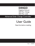
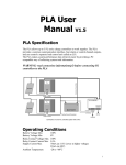
Ensure that you have followed the installation
instructions on pages 3-5 of the User Guide. The
Dingo can be used for system voltages up to 48V.
It is safe to connect the power before setting the
system voltage, even with a 48 volt battery.
Always mount the Dingo vertically with clear
airflow around the bottom and top of the case.
In hot conditions, do not put it in a sealed
enclosure, as this will restrict the airflow around
it. Do not install the Dingo in direct sunlight in
hot conditions.
Please consult section A.4 to determine the
performance that can be expected in hot
conditions.
The Dingo is specified for up to 60°C ambient
temperature. At full power, in high temperature
ambients, the LCD display may occasionally reach
a high enough temperature to become darker and
may become unreadable. It will return to normal
when it cools down.
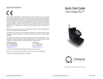
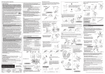
DINGO
Charge Controller
Alarm led
Button
High current
connections
T
Low level
connections
(plug in
terminal
block)
Mounting holes
Serial bus
port
Test
terminal
Cable tie
posts
Rev 1.5
4.02.13
Dingo 2020 Reference Manual
Features
The Dingo series of solar controllers is
exceptionally versatile. They give the user
unparalleled capability to adjust the function of the
controller and to monitor the performance of the
energy system.
To cater for non technical users, the Dingo has
four preset programs which can be used without
needing to understand the details of its operation.
For those with a good understanding of solar
regulation, there is another program, which allows
all the settings to be adjusted if required.
Once the program has been selected, it is
possible to disable any further adjustment. This
prevents unauthorised adjustment of settings.
Although the Dingo is primarily a device to control the
charging of batteries from solar electric (photovoltaic)
panels, it can also be used with other energy sources
such as wind, microhydro and fuel driven generators.
The Dingo supports a variety of regulation
methods. It supports slow speed switching and
fixed frequency pulse width modulation (PWM)
control in series and shunt modes.
settings can be stored on a computer and
uploaded into the controller. Data from the
controller can be downloaded into the computer
and displayed easily.
Overload Protection
The Dingo has overcurrent protection on both
the load and charge switches.
If the user accidently short circuits the load or
the charge connections, then the switch will turn
off very quickly before any damage is done to the
switch.
If the user overloads the load switch, then the
load switch will disconnect after a period of
time to protect itself from overheating. It will
reconnect automatically once the switch cools
If the charge input is overloaded, then the
controller will turn the charge switch off, as
required, to reduce the average charge current
into the Dingo.
For details see section A.4.
Thermal Protection
Low battery voltage load disconnection is
provided, as are an alarm, facility to control the
charging of a second battery bank and control for
a back up generator. The event controller can
be used to control lights, pumping, waste energy
use and other timer functions.
The Dingo has a temperature sensor on the
circuit board. The function of this sensor is to
tell the Dingo how hot its own circuit board is
so that it can reduce the charge current (the
major heating source) in order to protect against
overheating.
A temperature sensor can be added to correct
the regulation voltages for battery temperature.
See section A.4 for details of thermal derating
There is an input for measuring external voltages.
A serial interface is provided for accessories
including extra switch blocks, remote current
sensors and communication with a computer/
modem.
Menus
The Dingo has a simple main menu. This is
described in the user guide and provides most
the information required for normal use.
Using an external current shunt attached to
a remote current sensor (DSA) allows the
controller to see other current flows in the
system.
Behind each of the main menu screens are sub
menus. These are entered by doing a long push
in the main menu. They allow access to more
information and control of more advanced
features.
The Dingo can control larger systems by adding
external switch blocks attached to the serial bus.
The following pages describe each submenu in
detail.
The DUSB, D232 & DNET interfaces allow
remote monitoring and adjustment. Custom
5
1
Dingo 2020 Reference Manual
6
Rev 1.5
4.02.13
ABSB
FLOT
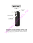
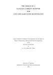
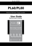
1.0 BATV Menu
The BATV screen, shown at power-up, displays
the real-time battery voltage.
A long push on the BATV screen will display the
state of the charge regulation cycle.
CHRG
LOAD
BOST
EQUL
IN
OUT
The Battery Charge Cycle
The Dingo’s sophisticated regulation system
is designed to keep the battery fully charged
without overcharging it.
To achieve this, it uses a charge control process
with three main states. These states are Boost,
Absorption and Float. It also uses a fourth state
from time to time, called the Equalisation state
(See fig 1B.)
1.1 BOST (Boost)
In the boost state, all the charge current available
is used to charge the battery. As the battery
charges, its voltage rises. When the voltage
reaches the boost maximum voltage (BMAX) and
remains there for 3 minutes, the controller will
automatically advance to the absorption state and
then, later, to the float state.
Returning to Boost state
To get this charge cycle to repeat, the Dingo
must return to the boost state. There are three
ways that it can do this.
DATA
SET
Fig. 1A - The BATV Menu Structure
a. Low Battery Voltage
If the battery voltage falls below the boost return
voltage BRTN for more than 10 minutes, then
the Dingo will switch back into the boost state.
The delay is necessary to prevent large short
term loads causing unnecessary returns to Boost.
b. Programmed boost cycles (optional)
The Dingo will automatically do a boost cycle
after a set number of days (BFRQ), regardless of
battery voltage.
c. Manual boost
The user can manually set the Dingo into the
boost state (or any of the regulation states).
To manually advance to the next state, do a
long push on BATV. This will show the current
regulator state. (BOST=Boost, EQUL=Equalise,
ABSB=Absorption, or FLOT=Float). A longpush on that state will manually advance into
the next state. Or, to return to the BATV screen
without changing the state, do a short push.
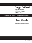
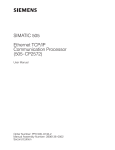
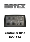
EMAX
Battery Voltage
1
BATV
BMAX
ABSV
ETIM
ATIM
Fig. 1B - The Battery Charge Cycle
FLTV
BRTN
BOOST
Time
EQUALISATION
ABSORPTION
FLOAT
BOOST
Rev 1.5
4.02.13
Dingo 2020 Reference Manual
Note: if ETIM is 0, then the Equalise state will be
bypassed. If ATIM is 0, then the Absorption state
will be bypassed.
On the BOST and FLOT displays, the battery
voltage is shown. On the EQUL and ABSB
displays, the time on the equalisation or
absorption timer is displayed. When this time
reaches the set time (ETIM or ATIM) the Dingo
will advance to the next state. Remember that
the timers will stop if the voltage falls too far
below the set point.
1.2 Equalise (optional)
Many battery manufacturers recommend that the
battery bank be given an overcharge occasionally.
This is a deliberate overcharge, designed to
equalise the voltages and specific gravities of all
the cells in the bank by bringing them all up to full
charge and to stir up the electrolyte in liquid cells
to reduce stratification.
The Dingo supports an automatic programmed
equalisation. This state allows the battery voltage
to rise until it gets to the equalisation voltage
(EMAX) and then remain at this voltage for the
set equalisation time (ETIM). This equalisation is
done every EFRQ days. (Typically 30-60 days).
Equalisation will begin at 9am on the appropriate
day. If ETIM is 0, then equalisation will not occur.
To prevent the controller being trapped in equalise
mode for a long time because there is inadequate
charge current to reach the equalise voltage, the
Dingo terminates equalise after 4 days
7
1.3 ABSB (Absorption)
In this state, the Dingo tries to keep the battery
voltage constant while the last part of the battery
charging occurs. This prevents excessive gassing
which occurs at high cell voltages. The Dingo
will keep the battery voltage at the absorption
voltage ABSV until it has been at this voltage for
the absorption time ATIM. When the absorption
time is finished, the Dingo advances to the Float
state.
If there is a cloudy period and there is insufficient
charge current to keep the voltage up to ABSV,
then the absorption timer will stop and resume
when the voltage comes back up to ABSV.
To allow some margin, the timer actually runs if
the voltage is above ABSV-HYST. (HYST is the
hysteresis setting used for slow speed switching
-usually about 0.4V)
1.4 FLOT (Float)
In this state, the battery has been fully charged.
The charge current is now used to keep the
battery voltage at a level which maintains full
charge. This voltage (FLTV) should be below the
gassing voltage to avoid excessive electrolyte
loss. If charge is drawn from the battery, the
Dingo will allow charging to resume until the
battery returns to FLTV.
2
Dingo 2020 Reference Manual
8
2.0 CHRG Menu
CHRG
The CHRG screen gives the real-time total
charging current (Amps). This total is the sum
of solar charge current (CINT) and any external
charge current. This may be current from an
external switchblock or MPPT device connected
to the bus or an external current measured using
a current shunt and a DSA.
2
CINT
From the charge screen, a long push displays
CINT (Charge Internal). This is the real-time
solar charge current flowing into the SOL+
terminal. (measured in amps.)
External Charge
From the CINT screen, a short push displays
the current reading from any external device
attached which can measure current. If the
device is a maximum power point tracker
(MPPT) then this device is shown as MPTx,
BATV
CINT
Rev 1.5
4.02.13
where x is the device number. Similarly, for
switchblocks the display is SWHx and for shunt
adaptors, SHNx. The device number can be
from 1 to 4 for shunt adaptors and from 1 to
12 for MPPT or Switchblocks. To fit the display,
numbers greater than 10 are given letters. So 10
is A, 11 is b and 12 is C.
This list also allows the user to check that the
Dingo has found or ‘discovered’ all the external
devices attached to the bus. This discovery
process is automatic. If a device is not on the
list and should be, then refer to section 8.4 for
troubleshooting advice.
Generator Control
The Dingo has a comprehensive generator
controller built in. It works in a similar way to the
Low Battery Disconnect function. It is designed
to give a run or stop signal to an electronic
start generator. It does not handle the actual
generator start-up sequence - this should be
done by the generator itself.
Fig. 2A - Generator Control Menus (PROG=4 only)
External
CHRG
LOAD
IN
OUT
DATA
0 or 4
SET
G ON
GOFF
GSET
Toggle function status on / off
GMOD
Set generator control mode
1 or 5
G ON
2 or 6
3
G ON
Set Voltage / SOC% to start generator
GOFF
S et SOC% to stop generator
GOFF
Set Voltage to stop generator
GDEL GDEL
Set delay before on/off change
SOC% SOC%
State Of Charge (SOC) Long push to adjust
GEXD GEXD GEXD
Set days between generator exercises
GRUN GRUN GRUN GRUN
Set length of generator exercise
GDAY GDAY
View/change number of days since last exercise
(or run time if generator running)
GDAY
Rev 1.5
4.02.13
Dingo 2020 Reference Manual
GSET
In the GSET screen, a long push will manually
change the state of the generator output. The
GEN indicator at the bottom of the screen is
visible when the generator function wants the
generator to be running. Note: the Generator
will not turn on during the ‘quiet time’, if
selected. (see below)
GMOD
The generator can operate in four different
modes. The generator mode is selected in the
GMOD screen and can be 0-6.
Quiet time: In modes 0,1 & 2, the generator is
not allowed to operate from 9pm until 9am so as
to enforce a ‘quiet time’.
Modes 4-6 are the same as modes 0-2 except
that there is no quiet time.
Note - do not confuse the GSET described in Figure
2A with the screen of the same name described in
Section 7.5.2. which sets the G terminal function.
GEXD (Generator Exercise)
To prevent the generator from seizing up, it
is good practice to exercise the generator
periodically. The Dingo supports this with an
Quiet Time M* No Quiet Time
GMOD: 0 1 2 3 4
5
6
•
•
• •
•
•
• •
•
•
•
•
• •
•
•
• •
•
•
•
•
•
•
•
•
•
•
•
•
•
•
•
•
•
•
•
•
•
9
Mode# Description
0. Turn on when battery voltage falls to G
ON for GDEL minutes. Turn off when the
voltage rises to GOFF for GDEL minutes.
Quiet time applies.
1. Turn on when the State of Charge (SOC%)
falls to G ON % of the battery capacity.
Turn off when the voltage rises to GOFF
for GDEL minutes. Quiet time applies.
2. Turn on when SOC % falls to G ON%.
Turn off when SOC% rises to GOFF%.
Quiet time applies.
3. Manual start. When started (in the GSET
screen) the generator will run for GRUN hours.
4. No quiet time. Turn on when battery
voltage falls to G ON for GDEL minutes.
Turn off when the voltage rises to GOFF
for GDEL minutes.
5. No quiet time. Turn on when the State
of Charge (SOC%) falls to G ON % of the
battery capacity. Turn off when the voltage
rises to GOFF for GDEL minutes.
6. No quiet time. Turn on when SOC % falls
to G ON%. Turn off when SOC% rises to
GOFF%.
Name
GON
GON
GOFF
GOFF
GDEL
SOC%
Description
Set V to start generator
Set SOC% to start generator
Set V to stop generator
Set SOC% to stop generator
Set delay before on/off change
Current SOC%
Long push to adjust
GEXD Set days between generator
exercise
GRUN Set length of generator exercise
GDAY View/change # of days since
last exercise
• = Active Parameter for relevant generator mode (GMOD)
*M = Manual
GMOD = GMOD Settings
Range
10-12.5V
0-99%
11.0-16.5V
1-100%
1-15 min
0-100%
2-60 days
0-4.0 hrs
2-60 days
2
10
automatic generator exercise function, which will
turn on every GEXD days. The number of days
since the last exercise is shown on the GDAY
screen. The generator will run for GRUN hours.
When exercising, the elapsed time is shown as
GTIM. Both GDAY and GTIM can be adjusted.
Note:
2
Rev 1.5
Dingo 2020 Reference Manual
1. There is no generator exercise when GMOD = 3
(manual start).
2. GSET toggle does not work during generator
exercise
3. A small amount of overcharge will occur if
battery is already fully charged. Use a low GRUN
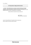
value if this is of concern.
GDEL (Generator changeover delay)
Generator Control
For many generators it is possible to control their
operation remotely. This is either a remote start or
run function built into the generator or a separate
remote start unit.
There is usually a pair of contacts that will cause
the generator to run if they are closed. This can be
done with a switch or a relay.
The Dingo provides a G relay which can be used
for this purpose. This relay is voltage free and solid
state. It can carry a current of up to 300mA and
can block 85V.
For some generators it is possible to connect the
G relay directly to the remote start input on the
generator. The wiring for this is shown in fig 2B.
A programmable delay (in minutes) is used to
prevent false turn on or off of the generator due
to large transient loads. Default setting is 10 min.
The generic programs (PROG=0-3) use
voltage driven generator control (GMOD=0).
See “settings used in Programs 0-3” for on-off
voltages etc.
Generator Example
4.02.13
Fig. 2B - Generator start relay wiring
V
BOOST
For example, if SOC% triggered generator on,
voltage-triggered generator off, and no quiet
time, is desired, set up the regulator as follows:
S- B- L- S+ B+ L+
T
PROG = 4
GMOD = 5
Allows user adjustment.
SOC % ON, Voltage OFF,
no quiet time
CHRG menu : Set GON, GOFF, GDEL,
GEXD, GRUN as required
SET/REG :
Check these settings are
correct for your battery type
Mode menu : GSET if using ‘G‘ terminal for
generator control
GSET = 2
or
LSET if using LOAD terminal
LSET = 2
for generator control
Note: when changing from prog 0-3 to program 4,
the user can load the default settings for program 1
into the Dingo using the DFLT screen in the MODE
menu. See section 7.5.8. This can save a lot of time.
Generator
Remote
Start Unit
Generator controlled directly by the G relay
Rev 1.5
4.02.13
Dingo 2020 Reference Manual
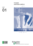
This direct connection will work if the current
flowing through the remote start terminals is less
than 300mA. If the current is greater than this,
then it will be necessary to use an intermediate
relay with a higher contact current rating. The G
relay switches the intermediate relay which in turn
switches the remote start terminal. The wiring for
this is shown in fig 2C.
Chose a relay with a contact current rating suitable
for the remote start unit and a coil voltage which
is the same as the system voltage. The relay
coil should not draw more than 300mA when it
is energised. Be careful with automotive relays
because they can often be poor relays requiring
large coil currents. Use relays from the electronics
industry which generally have lower drive power.
11
V
BOOST
S- B- L- S+ B+ L+
T
2
The G relay terminals do not need a catch diode
across the relay coil to protect from the flyback
voltage. This protection is built into the G terminal.
NO
It can be difficult to determine what current is
required to operate the remote start. The best way
to do this is to measure it. Short the remote start
terminals with a multimeter on its current range
and measure the current.
The manufacturer’s manual should contain this
information but often does not.
The generator control provided by the Dingo is
simple -a contact closure is provided when the
generator should run and the contacts open when
the generator should be stopped. It does not handle
the issues associated with starting such as fuel and
what to do if the generator does not start. This
should be handled by the remote start unit.
Intermediate Relay
Generator
Remote
Start Unit
G relay switches a larger relay
Fig. 2C - Generator start wiring with an
intermediate relay.
12
Rev 1.5
Dingo 2020 Reference Manual
3.0 LOAD Menu
BATV
LINT
4.02.13
External
CHRG
LOAD
LOAD
The LOAD screen gives real-time total load
current (in Amps). This total is the sum of
the current flowing through the load terminal
(LINT) and any external load current. This may
be current from an external switchblock or an
external current measured using a current shunt
and a DSA.
LINT
3
From the LOAD screen, a long push displays
LINT (Load Internal). This is the real-time load
current used by equipment connected to the
regulator’s LOAD terminal.
External Load
From the LINT screen, a short push displays
the load current reading from any external
device attached which can measure current. If
the device is a maximum power point tracker
(MPPT) then this device is shown as MPTx,
where x is the device number. Similarly, for
switchblocks the display is SWHx and for shunt
adaptors, SHNx. The device number can be
from 1 to 4 for shunt adaptors and from 1 to
12 for MPPT or Switchblocks. To fit the display,
numbers greater than 10 are given letters. So 10
is A, 11 is b and 12 is C.
This list also allows the user to check that the
Dingo has found or ‘discovered’ all the external
devices attached to the bus. This discovery
process is automatic. If a device is not on the
list and should be, then refer to section 8.4 for
troubleshooting advice.
Name Description
LOFF Set voltage at which load
disconnects
LON Set voltage at which load
reconnects
LDEL Set delay before
switching on/off
Range
10.0-12.5 V
11.0-16.0 V
0-15 min
IN
OUT
DATA
SET
LSET
LOFF
L ON
LDEL
Toggle low battery
disconnect status on/off
Set voltage at which
load disconnects
Set voltage at which
load reconnects
Set delay before
switching
Fig. 3A - LOAD Menu
Low Battery Disconnect
(LSET, LOFF, LON, LDEL)
To prevent battery damage due to overdischarge, the Dingo has a function which turns
off the load if the battery voltage falls too low.
If correctly configured, equipment connected to
the Load+ terminal (the “load”) will be turned
off when the battery voltage falls below the
LOFF voltage for LDEL minutes. Once turned
off, the load will not be reconnected until the
voltage rises above the L ON voltage for LDEL
minutes. The L ON voltage should be set high
enough so that some recharge will have taken
place before reconnection, otherwise the
disconnection process can oscillate.
This feature is optional, and can be disabled
either by connecting the user load directly to
the battery, or by setting LOFF low enough so
that the low battery disconnect function never
activates.
The LOAD indicator at the bottom of the screen
is visible when the low battery disconnect
function wants to disconnect the load. (Note
that other settings can override the function, so
the LOAD indicator does not necessarily mean
that power has actually been disconnected
from the load.) When the disconnect timer has
begun to timeout, the alarm led will flash at a 2
second rate with the led mostly on. If the load
disconnect function operates, then the alarm led
continues flashing but with the led mostly off.
The Low Battery Disconnect function can also
be toggled manually by a long push when in LSET
menu (see Figure 3A).
Rev 1.5
4.02.13
Dingo 2020 Reference Manual
Selecting a load switch
BATV
The low battery disconnect is an internal logical
function. To do something other than act as
a warning, it has to be used to control a load
switch.
CHRG
This can be done in three different ways. It can
control the Dingo’s LOAD terminal, or the G
(General Purpose Output) relay or an external
switchblock attached to the bus. The sense of its
operation can also be reversed, i.e. it can turn on
the terminal when the function decides the load
should be disconnected. This can then be used as
a low battery alarm or to drive a relay to turn off
other loads.
The connection to real switches is set up in the
MODE menu. See section 7.5 for details.
DO NOT CONNECT AN INVERTER OR
ANOTHER BATTERY TO THE LOAD
TERMINAL. This terminal is rated at 20A.
Most inverters draw larger currents than
this and have their own low battery cut
off circuitry anyway. In general, Inverters
should be connected directly to the battery.
13
Fig. 4A - IN Menu
LOAD
IN
OUT
DATA
INT
External
Clear
Clear
SET
5.0 OUT Menu
OUT
The OUT screen gives a running total of Amp
hours (Ah), or energy, that has been used during
the day (since midnight). This total is the sum of
Ah used by equipment connected to the LOAD
terminal and any external devices.
OUT/INT
4.0 IN Menu
From the OUT screen, a long push displays INT
(Internal Ah OUT). This is the running total of Ah
used by equipment connected to the regulator’s
LOAD terminal. A long push will clear this total.
IN
OUT/External
The IN screen gives a running total of Amp
hours (Ah), or energy, that has been put into the
battery during the day (since midnight). This total
is the sum of Solar Ah collected directly through
the Dingo and any measured external Ah input.
From the INT screen, a short push displays any
external load Ah. Long push to clear.
Note: the net battery Ah is the IN Ah -OUT Ah.
The IN and OUT Ah counters are reset each day
at midnight.
IN/INT
From the IN screen, a long push displays INT
(Internal Ah IN). This is the running total of Ah
collected through the SOL terminal over the day
(since midnight). A long push will clear the INT
running total.
IN/External
From the INT screen, a short push displays any
external Ah contributions. This is the running
total of each external Ah input from MPPT,
Switchblock or current shunt measurements. A
long push will clear a total.
BATV
Fig. 5A - OUT Menu
CHRG
LOAD
IN
OUT
DATA
SET
INT
External
Clear
Clear
4
5
6.0 DATA Menu
This time will only be recorded if the regulator
has done a transition into float that day. A time
will not be recorded if the controller did not
reach the float state or stayed in float all day. No
float time displays as a ‘-’.
A long-push on DATA, enters the data menu.
This displays performance information for the
current day.
The screens in the DATA menu have the
following meanings:
VMAX maximum battery voltage since midnight.
VMIN minimum battery voltage since midnight.
FTIM time of day the regulator entered the
Float state.
SOC estimated state of charge of the
battery based on the amp hours in and
the amp hours out. A very rough ‘fuel
gauge’ -see below for further details.
TEMP temperature being sensed by the
external temperature sensor (if attached).
SOLV solar panel voltage (open circuit)
HIST entry point for history data.
6.4 SOC (State of Charge Display)
SOC (State Of Charge) should be read as a
percentage estimate of how full the battery is.
This estimate is based on the amp hour balance
counter. The counter keeps a running balance
of amp hours in vs amp hours out. The SOC
display shows this balance as a percentage of the
battery size. Note that all system currents must
be monitored by the regulator and the battery
capacity must be entered by the installer at the
BCAP setting before SOC will be meaningful.
SOC (%) =
At midnight, VMAX, VMIN, FTIM, SOC, IN and
OUT are stored in the history data and cleared
from the current day readings.
6.3 FTIM (Float time Display)
FTIM indicates the time of day that the regulator
BATV
CHRG
LOAD
IN
VMAX
VMIN
FTIM
SOC
1. When the controller state changes from
boost to absorption, SOC is set to 90% if it
is <90%. When the controller state changes
from absorption to float, SOC is set to
100%.
2. Charge current is
corrected for loss
due to gassing,
based on the battery
TEMP SOLV HIST
voltage.
Toggle setting lockout
("A" showing means setting adjustable)
OUT
DATA
SET
Ah balance counter x 100
BCAP
Over time, a pure amp hour balance counter
will drift out of line with the real battery state of
charge. To keep the counter better aligned with
reality, the Dingo automatically makes a number
of corrections:
6.1 & 6.2 VMAX and VMIN
VMAX and VMIN respond very slowly to changes
in battery voltage. This allows them to ignore
short term voltage fluctuations. A long push will
reset the value to the current battery voltage.
4.02.13
changed from the ABSB (Absorption) state to the
FLOT (Float) state.
(Retrieving Performance Data)
6
Rev 1.5
Dingo 2020 Reference Manual
14
Fig. 6A -The DATA Menu Structure
3. A correction for self
discharge is made
daily (at midnight)
This is temperature
corrected.
4. A slow correction
is applied where
the SOC inferred
Rev 1.5
4.02.13
Dingo 2020 Reference Manual
from the battery open circuit voltage can be
determined. A temperature sensor must be
attached for this correction to work accurately.
If you use a temperature sensor, you will get a
more accurate SOC estimate.
A long push on the SOC screen will allow the
SOC to be adjusted to the users best estimate of
the present SOC.
The SOC figure should be treated with caution,
as there are many reasons that it may be
inaccurate:
• The Dingo does not automatically have
knowledge of the whole system. It only
knows what you tell it. For SOC to work
well, it must be measuring all charge (Ah
in) and discharge (Ah out). If the battery
can charge or discharge without the Dingo
knowing, SOC will not be very accurate.
• The effective capacity of the battery reduces
with age. BCAP should be reduced in older
batteries to adjust for this.
• When you set up BCAP on installation, you
should choose your best guess of the batteries
actual capacity when used in the way you
intend to use it. For example, if you think the
battery will mostly be charged and discharged
at around the 20h rate (C/20) you should set
the capacity of you battery at the 20h rate
from the manufacturer’s literature. If you
expect the battery to be used at a variety of
charge and discharge currents, try to estimate
an average.
• Peukerts equation can be used to estimate
the loss in capacity at higher discharge rates.
Correction based on Peukerts equation is not
done automatically because it does not model
discontinuous and variable rate discharge very
well and changes with battery age.
6.5 TEMP (Display External Battery
Temperature and Setting Lockout)
This screen displays the external battery
temperature sensor reading (if attached) or “-”
if it’s not. It is also used to adjust Setting Lockout
(see figure 6.A).
15
Setting Lockout
In some cases it is desirable to restrict the ability
to adjust settings, so as to prevent unwanted
tampering.
To disable settings, long push on the TEMP
screen. The “A” indicator will disappear. A useful
memory aid is to consider that “A” stands for
“Adjustable” on this screen.
To enable adjustment of settings again, long
push on the TEMP screen again. If you have
successfully enabled settings adjustment, the “A”
will reappear while TEMP is showing.
The controller remembers the state of the
settings lockout when the power is disconnected.
6.6 SOLV (Solar Voltage Display)
This screen displays the open circuit solar panel
voltage
The charge current through the SOL terminal
is turned off while the Dingo is displaying this
screen. If the view is left on the SOLV screen, the
charge current will be automatically reconnected
after 18-24 minutes. This is to prevent battery
failure due to lack of charge (failsafe).
6.7 HIST (History display)
Six pieces of data are recorded each day. These
are:
Total Ah IN for the 24hrs. This is a measure of
the energy collected that day
Total Ah OUT for the 24hrs. This is a measure of
the energy used that day.
VMAX - the maximum battery voltage that day.
VMIN -the minimum battery voltage that day,
FTIM - time of day the controller changed to
float mode. ( ‘-’ if it didn’t)
SOC. -the state of charge at the end of the day
These figures are a very good guide to how well
the solar system is performing. The user can
compare the energy collected with the energy
used and get some feedback about the balance
between collection and use.
6
Rev 1.5
Dingo 2020 Reference Manual
16
These records are available for the past 99 days
on the screen of the controller. The controller
actually keeps records for over one year, but for
practical reasons, these can only be accessed via
the computer interface. The records are not lost
if the power is disconnected.
At the start of each day record is the DAY
screen. This shows which day’s data you are
looking at (DAY 1 = yesterday, DAY 2 = the day
before yesterday, etc.)
4.02.13
A long push on each of the screens except EXIT
will move down to the next day or the next day’s
value. Short pushes move between figures for
the same day.
NEXT goes to the next day, BACK goes to the
previous day. The day numbers wrap around
when they reach the end.
A short push on the EXIT screen will take you
back to the beginning of that day’s record. A long
push will exit back to the DATA screen.
For help with navigating through the History,
refer to Fig.6B.
Fig. 6B - The History Menu
BATV
Thin arrow = short push
Thick arrow = long push
CHRG
LOAD
IN
VMAX
VMIN
FTIM
SOC
TEMP
HIST
SOLV
Long push Toggle setting lockout
to adjust (’A’ showing means
settings adjustable)
OUT
DATA
SET
6
DAY 1
DAY 2
IN
IN
OUT
OUT
VMAX
VMAX
VMIN
VMIN
FTIM
FTIM
SOC
SOC
NEXT
BACK
EXIT
DAY 2
DAY 99 DATA
NEXT
BACK
EXIT
DAY 3
DAY 1
DATA
DAY 3
IN
OUT
VMAX
VMIN
FTIM
SOC
NEXT
BACK
EXIT
...
...
...
...
...
...
...
DAY 4
DAY 2
DATA
DAY 99
IN
OUT
VMAX
VMIN
FTIM
SOC
NEXT
BACK
EXIT
DAY 1
DAY 98
DATA
Rev 1.5
4.02.13
7.0 SET menu
The set menu contains most of
the settings which control the
operation of the controller.
7.1 TIME
This screen displays the time on
the controller’s clock. A 24hr
format is used for system time,
with a resolution of 6 minutes (0.1
hours) So, for example, 14.3 is
2:18 PM.
Dingo 2020 Reference Manual
17
Fig. 7A - The SET Menu
BATV
CHRG
LOAD
IN
OUT
DATA
SET
NOTE: Removing power to the regulator (i.e. turning
it off) will reset the system time to 10.0hrs (10:00
AM).
The time must be set whenever the regulator
is restarted. Incorrect system time will result
in misleading history data since this is stored at
midnight of each day. Generator quiet-time and
time-driven event control will also be affected.
7.2 VOLT
Set VOLT to the nominal system voltage for the
installation.
This setting determines the regulation and
control voltage set-points for the system. For
correct regulation, this setting MUST be correct.
NOTE: The controller will not be damaged if
the voltage is set incorrectly but the battery will
probably be damaged (under- or overcharge) if
this setting is in error for more than a few days.
7.3 PROG (Adjusting Regulation
Settings)
The Dingo comes with a number of preconfigured
programs, which are set up for generic batteries.
For custom installations, selecting program 4
allows the user to adjust each setting individually.
If you find you are unable to change your settings, it
may be because the “lockout” setting is activated.
This setting is designed to prevent unwanted
tampering— please see the “Setting Lockout”
information in section 6.5.
TIME
Set
time
VOLT PROG
Set
battery
voltage
REG
MODE
EVNT
Set
program
Program Function Table
(Generic Programs)
Program#:
0
1
2
3
Batt Type: Flooded Sealed Flooded Sealed
LOAD Term No Night Light
Night Light
Functions:
Low Battery Disconnect
Low Battery Disconnect is enabled for Programs 0-3.
Programs 2&3 turn on the LOAD terminal at night
for lighting applications.
Program Description
PROG 0: Use with liquid electrolyte lead acid
(ie. flooded) batteries. The LOAD terminal is
set to turn off when the battery is low. (Also
known as Low Battery Disconnect)
PROG 1: Use with sealed or gel lead acid
batteries. The LOAD terminal is set to turn off
when the battery is low.
PROG 2: Use with liquid electrolyte lead acid
batteries (ie. flooded). The LOAD terminal
is set to turn on all night and can be used for
night lighting. It will turn off when the battery
is low (Low Battery Disconnect).
PROG 3: Use with sealed gel lead acid batteries.
The LOAD terminal is set for night lighting, with
low battery disconnect.
PROG 4: Enables customised adjustment of all
settings.
Installation instructions for programs 0-3 are on
pages 8-9 of the User Guide.
7
4.02.13
Settings Used in Programs 0-3
SET/MODE
When programs 0-3 are selected, the Dingo
automatically uses the values below in its
regulation. These are not visible on the screen
and are not adjustable by the user. For adjustable
settings, choose program 4.
Parameter
0
1
2
3
LSET
GSET
ESET
BSET
BAT2 (V)
PWM
ALRM (V)
1
2
1
4
2
9
see below
0
2
14.0
1
11.4
4
9
The voltage settings are shown correct for 12V
operation. For higher voltages, scale these up (eg.
for a 24V system, multiply each voltage figure by
2.)
CHRG
Parameter
GMOD
G ON (V)
GOFF (V)
GDEL (Min)
GEXD (Day)
GRUN (Hr)
LOAD
Parameter
LOFF (V)
L ON (V)
LDEL (Min)
7
Rev 1.5
Dingo 2020 Reference Manual
18
Setting for program number
0
1
2
3
0
11.5
13.8
10
30
1.0
0
1
2
3
11.3
12.8
10
SET/REG
Setting for program number
Parameter
BMAX (V)
EMAX (V)
ETIM (Hr)
EFRQ (day)
ABSV (V)
ATIM (Hr)
FLTV (V)
HYST (V)
BRTN (V)
CLIM (A)
BFRQ (Day)
TCMP
0
15.0
16.0
1.0
1
14.2
14.0
0
45
14.0
2.0
13.8
0.4
12.3
20
15
0
2
15.0
16.0
1.0
3
14.2
14.0
0
0
2
SET/MODE/
Default Settings
ESET
(see section 7.5.2)
SW 1 to C
0 (charge switch -on to charge)
SET/EVNT
Setting for program number
Setting for program number
Parameter
STRT
TIME (Hr)
STOP
TIME (Hr)
EMOD
TMOD
Setting for program number
0
1
2
3
0
0
0
25.5
2
0
Settings for Program 4
If program 4 is selected, then all settings can be
accessed and adjusted.
After TIME, VOLT and PROG, there are entry
points for three further sub menus:
REG
Allows the user to customise the
regulation settings (see below for details).
MODE Allows the user to adjust other
configuration options.
EVNT
Settings for the event controller.
Rev 1.5
4.02.13
BATV
Dingo 2020 Reference Manual
TIME
VOLT
PROG
REG
19
MODE
EVNT
CHRG
LOAD
BMAX
Set max boost voltage
IN
EMAX
Set max equalisation voltage
OUT
ETIM
Set equalisation time
EFRQ
Set # days between eq.cycles
ABSV
Set absorbtion voltage
ATIM
Set absorbtion time
FLTV
Set float voltage
HYST
Set hysteresis
BRTN
Set boost return voltage
CLIM
Set charge current limit
BFRQ
Set max days to between boost cycles
TCMP
Set temp compensation profile
DATA
SET
Fig. 7.4A - Regulation Settings (Program 4 only)
7.4 REG menu (Customising
Regulation Settings)
[PROG=4 only]
To adjust the regulation settings, long-push on “SET”,
short-push to “REG”, and long-push (see fig 7.4A).
The settings given below are for 12V systems.
For other system voltages the value can be scaled
from this. (eg. for a 24V system, multiply all
voltages by 2.)
SET/REG Submenu Summary:
Name
BMAX
EMAX
ETIM
EFRQ
ABSV
ATIM
FLTV
HYST
BRTN
CLIM
BFRQ
TCMP
Description
Maximum voltage in
boost mode
Equalisation voltage
Equalisation time
Number of days between
equalisation cycles
Absorption voltage
Absorption time
Float voltage
Hysteresis used when
not in PWM mode
Voltage below which
return to Boost mode
occurs
Charge current limit
Range
13.5-16.5V
14.0-17.0V
0-2.0 hours
20-150
13.5-15.5V
0-4.0 hours
13.0-15.0V
0.1-1.0V
11.0-13.0V
0.5-20A
Maximum number of days 1-20
between boost cycles
Selection of temperature 0-8
compensation profile
(see below 7.4.3)
7.4.1 HYST (Hysteresis Value)
When not in PWM mode, the Dingo controls
the battery voltage by simply switching the
charge current on and off. It turns off the charge
current at the relevant voltage set point for the
state (Float, Boost, Equalise, Absorption), and
allows the charge current to turn back on at a
slightly lower voltage. The gap between the two
voltages is called hysteresis.
Example:
With the Dingo in float mode and slow switching
(i.e. not using PWM), the charge current will
be turned on until the battery voltage rises to
the FLTV value. Once the FLTV value has been
reached, the charge current will be turned off
until the battery voltage falls to FLTV – HYST
(float voltage minus the hysteresis value) at
which time the charge current will be turned
on again until the battery reaches FLTV and the
cycle begins again.
The larger the hysteresis values, the slower the
rate of switching on and off will be.
NOTE: When switching a mechanical relay for
regulation purposes, the HYST value may need to
be increased so that the relay does not wear out
quickly due to rapid switching.
7
20
Dingo 2020 Reference Manual
Timers:
The HYST value is also used to start and stop
the timers associated with the different regulator
charging states (Boost, Equalise, and Absorption).
TCMP Function
Example Battery
0
-5mV°C linear
auto sense
(default)
gentle curve
auto sense
steeper curve
auto sense
limited range
curve
auto sense
General Purpose use this if in doubt
-5mV°C linear
non auto sense
gentle curve
non auto sense
steeper curve
non auto sense
limited range
curve
non auto sense
General Purpose use this if in doubt
BP Solar Block
When the Dingo changes to the Absorption state,
an internal timer is started to monitor how long
the regulator has been in Absorption. If however
the battery voltage falls lower than ABSV - HYST
this timer is stopped, and starts again when the
battery voltage rises above ABSV - HYST. This
ensures that the regulator holds the system in the
required state for the correct programmed time
and doesn’t continue to the next charging stage
until this time has elapsed.
1
NOTE: An exception to this is the Equalise
State, which will terminate after 4 days if unable
to complete the full specified time period.
5
7.4.2 CLIM Charge Current Limit
7
This allows the Dingo to protect itself from
overheating due to excessive charge current. The
maximum charge current can also be limited for
small batteries where the full array current might be
too much for the battery. This is useful for systems,
which are marginal in winter, but have too much
charge current for the battery in summer.
7
It can also be useful where there is an initial
ageing effect in the first few months of the life
of the module. For example, with amorphous
modules the initial current may be more than the
charge current rating of the Dingo. Making use of
this feature, panels can be installed with the full
rating calculated after the initial drop off.
NB. Current limiting is only done for the Dingo.
It is not done for the external charge switches.
7.4.3 TCMP
(Temperature compensation)
(Default=0, Adjustable in Program 4 only)
A temperature sensor is available which allows the
4.02.13
SET/REG/TCMP Selection Summary:
Example:
The Dingo has a built-in charge current limit. If
the charge current exceeds the CLIM setting,
the charge duty cycle will be reduced to limit the
average charge current.
Rev 1.5
2
3
4
6
8
BP Solar Block
Sonnenshein Dry Fit
Absolyte battery
Sonnenshein Dry Fit
Absolyte battery
No temperature (Failsafe if short
sensor
across T- T+ inputs)
Note: Without a temperature sensor fitted, the
Dingo TEMP display will be blank if autosense is
enabled and shows -21oC if non autosense.
Dingo to adjust its regulation voltage settings to
compensate for variations in battery temperature.
The setting TCMP is used to select a temperature
profile, which determines how this compensation
is achieved.
The Dingo can automatically sense the presence
of a temperature sensor if one of the autosense profiles is selected. However, if operation
at temperatures below -12oC is common, it
is better to use the non auto sense profile
(TCMP=4-7). The auto sense will not detect
sensors colder than -16oC
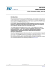
Fig. 7.4.3B shows the temperature compensation
curves for each TCMP setting. Consult the
battery manufacturer for correct compensation
for the battery used.
Rev 1.5
4.02.13
Dingo 2020 Reference Manual
21
Connecting a Temperature
Sensor
D
T
B
The temperature sensor should
be connected to the T+ and Tterminals on the green terminal
block (see p37). The sensor
wire with the stripe goes to
the T– terminal and the sensor
wire without the stripe goes to
T+ terminal. The wires may be
extended if necessary without
affecting the accuracy.
Neoprene
sponge
D
T
Note: The DTB (bolt-on metal
lug) has no electrical connection
to metal lug housing, so it can be
connected to either the negative
or positive battery terminal.
2.5
2.45
2.4
temperature
sensor
mounting
Battery
Battery
DT
DTB
Fig. 7.4.3A - Attaching a Temperature Sensor to a battery
2,6
TEMPERATURE COMPENSATION CURVES
0,4
1,5
Diagram Key
= Linear
= Gentle Curve
= Steeper Curve
= Limited Linear
2.35 3,7
2.3
V/Cell
2.25
Autosense characteristics
below -16oC
2.2
3,7
1,5
Non-Autosense should be used
if battery temp likely to go below -12°C
2.15
2,6
2.1
2.05
-20.00
Normalised to 2.25V/cell
-10.00
0.00
10.00
-16°C (MIN)
Fig. 7.4.3B - Temperature compensation curves
0,4
23°C
20.00
30.00
Temperature °C
40.00
50.00
60.00
7
BATV
Rev 1.5
Dingo 2020 Reference Manual
22
TIME
VOLT
PROG
REG
MODE
4.02.13
EVNT
CHRG
LOAD
IN
OUT
DATA
SET
Fig. 7.5A - MODE Menu
LSET
Set function of LOAD terminal
GSET
Set function of general purpose terminal (G)
ESET
Set control of external switches
BSET
Set function of B input
BAT2
Set Regulation voltage for 2nd battery control
PWM
Set which terminals use Pulse width Modulation
BCAP
Set amp Hour capacity of the battery (20-20,000AH)
ALRM
Set voltage at which to activate alarm
RSET
Reset system (losing today’s data and time)
DFLT
Reload factory default settings
7.5 MODE Menu (Adjusting Configuration Settings) [PROG=4 only]
The MODE submenu contains most of the
settings for the configuration of the Dingo other
than the main regulation settings.
regulation by dumping the input energy.
f. Event controller. An output which is active
when a specified set of conditions occurs.
7.5.1 LSET & GSET
SET/MODE Selection Summary:
There are two output terminals on the Dingo
(LOAD and “G”) and six logical control functions.
The LSET and GSET settings define which of
the six functions controls each of these output
terminals.
Note that the settings described below are different
from the LSET and GSET screens described in
Section 2 and 3.
The six internal control functions are:
7
a. Low battery disconnect. This also controls
the “LOAD” indicator at the bottom of the
screen.
b. Run the backup generator. This also controls
the “GEN” indicator at the bottom of the
screen.
c. Charge a second battery. Indicates when the
solar input can be diverted to a 2nd battery.
d. Battery voltage alarm output. Provides an
output based on the battery voltage.
e. Shunt regulation. Gives an output useful for
Name Description
Range
LSET Select the control of
the LOAD switch
0-11
GSET Select the control of
the “G” relay
0-11
ESET Select the control for
see 7.5.2
external switchblocks
BSET Select the use of the
B+ sense input
0-3
BAT2 Regulation voltage for
2nd battery control
13.0-16.0V
PWM Select which terminals
use PWM (SOL, LOAD) 0-3
BCAP Amp hour capacity of
the battery bank
20-20,000Ah
ALRM Alarm voltage
10.0-18.0V
RSET Resets the controller (warm reboot).
Clears day data and time
DFLT Resets Prog 4 settings to Prog 1 settings.
Used to reset factory default settings.
Rev 1.5
4.02.13
Dingo 2020 Reference Manual
SET/MODE/LSET
# Function
0 Low battery
disconnect
Terminal is:
on when function
wants to disconnect
battery
1 Low battery
off when function
disconnect
wants to disconnect
(default)
battery
2 Generator
on when function
control
wants to run generator
3 Generator
off when function
control
wants to run generator
4 Event control
on when event is on
5 Event control
off when event is on
6 2nd battery
on when battery 2
charge control
should charge
7 2nd battery
off when battery 2
charge control
should charge
8 Alarm output
on when battery
voltage < alarm setting
9 Alarm output
off when battery
voltage < alarm setting
10 Shunt control
off when function
(Must be selected wants to disconnect
for PWM control the shunt load
of the LOAD(ON for regulation)
terminal)*
11 Shunt control
on when function
(PWM must not
wants to disconnect
be set to 2 or 3)* shunt load (OFF for
regulation)
23
SET/MODE/GSET
#
0
Function
Low battery
disconnect
Low battery
disconnect
Generator
control (default)
Generator
control
Event control
Event control
2nd battery
charge control
2nd battery
charge control
Alarm output
Terminal is:
on when function wants
to disconnect battery
1
off when function wants
to disconnect battery
2
on when function wants
to run generator
3
off when function wants
to run generator
4
on when event is on
5
off when event is on
6
on when battery 2
should charge
7
off when battery 2
should charge
8
on when battery voltage
< alarm setting
9 Alarm output
off when battery voltage
< alarm setting
10 Shunt control** off when function wants
to disconnect shunt load
(ON for regulation)
11 Shunt control** on when function wants
to disconnect shunt load
(OFF for regulation)
** Note: PWM is not available on G Terminal
* Don’t use LSET=11 with PWM, as design does
not allow inversion of PWM signal.
The LSET setting allows the user to choose
which function controls the electronic switch
connected to the LOAD terminal. The user can
also select whether that switch is on or off when
the function is active. (i.e. select normally open
or normally closed)
If LSET is set to 9, then the load switch would
turn off when the battery voltage goes below the
ALRM setting. This could be used to turn off a
load to reduce the drain on the battery.
For example, if LSET is set to 8, then the load
switch would turn on if the battery voltage is
lower than the alarm voltage setting (ALRM).
This could be used to turn on an alarm light.
The GSET setting allows the user to choose
which function controls the general purpose “G”
relay, and whether it is on (closed) or off (open)
when the function is active.
7
24
Dingo 2020 Reference Manual
Shunt Control
The Dingo supports either series control,
shunt control, or both at the same time. In
a hybrid system, the main solar component
is controlled by the SOL input and the other
charge component (wind, hydro, etc) is directly
connected to the battery and controlled by a
dump load which diverts excess charge. The
dump load is managed by the shunt control
function. This can operate via the LOAD or ‘G’
terminal either directly or through a relay. These
functions are configured in the LSET and GSET
screens. (see above)
Regulating Wind / Hydro:
Shunt control is appropriate for wind generators
or microhydro systems, which require a constant
load on the charging source so the generator
doesn’t overspeed and destroy itself. In this case
the charging source must remain connected to
the battery at all times.
“Shunt control” (also referred to as “diversion
control”) refers to the technique of controlling
the battery voltage by drawing energy from
the system with a ‘dump load’, rather than
disconnecting the charge source as “series
control” does on the solar input.
To regulate a wind or microhydro installation
with shunt control, a dedicated dump load must
be available for the Dingo to switch across the
battery. The dump load current should be larger
(at the range of expected battery voltages) than
the maximum charge current available from your
generator.
The function of the dump load is to ‘soak up’
energy coming in which the battery cannot store
in order to maintain the desired battery voltage.
7
7.5.2 ESET: External switch setup
The Dingo has a serial bus which allows the
user to add external devices to increase the
control system’s capability. One such device is an
electronic switch. This can be used to increase
the charge current being regulated or increase
the load current being controlled by the load
disconnect function.
The user needs to select which internal function
Rev 1.5
4.02.13
will control each external switch block. This
is done in the ESET sub menu. A long push on
ESET brings up the first switch setting. Short
pushes move to the next switch until ESET
returns after switch C.
The following table shows the control options.
SET/MODE/ESET Selection Summary:
Selection Function
0
Charge control (normal/slow)
On when Dingo wants to charge
1
Charge control (shunt/slow)
Off when Dingo wants to charge
2
Load disconnect (inverse)
On when load should be off
3
Load disconnect (normal)
Off when load should be off
4
Alarm (normal)
On when battery<ALRM voltage
5
Alarm (inverse)
Off when battery<ALRM voltage
6
Event (normal)
On when the event is active
7
Event (inverse)
Off when the event is active
7.5.3 BSET: Configuring the B+ Sense
Input
The terminal labelled B+(right most terminal of
the green terminal block) is intended as a sense
input for the battery positive voltage. This can
be connected directly to the positive terminal of
the battery so that the true battery voltage can
be read. This is important if there is significant
voltage drop along the wiring (including any fuse)
between the BAT+ terminal on the Dingo and
the real battery positive. (If there is significant
voltage drop on the negative side, then take the
BAT- terminal directly to the battery negative via
a fuse. The fuse need only be rated for the Dingo
supply current, say 100mA. Take the negative
side of the charge current from the array to the
battery separately via it’s own fuse. The intention
is that the array current does not pass through
the same wire as the Dingo negative supply
current). See figure 7.5.3A
Rev 1.5
4.02.13
Dingo 2020 Reference Manual
25
Fuse/Breakers
V
+
T
Solar
Panel(s)
Battery
+
–
S- B- L- S+ B+ L+
Connect
close to
battery
terminals
-
BOOST
Fuse/
Breakers
B+ Sense wire
(Connect to Battery
Positive Terminal)
(NOTE: Low Current 'B Sense' wires can be significantly smaller than other wires.)
If the B+ input is not being used for this, then it
can be used for sensing the voltage on a second
battery being charged or for providing a voltage
input for the event controller (VEXT).
Some inverter-chargers, such as the SP PRO,
can communicate to the charge controller when
they want to export power to the grid. Selecting
BSET=3 enables this.
‘Push Button’ Switch Input
To use the B+ sense input as a switch event
input, wire a switch (or other voltage free
contact closure device) between the B+ terminal
(green terminal block) and the Bat+ terminal
(and set BSET = 2). See Figure 7.5.3B
Fig. 7.5.3A - Battery Sense Input
Fig. 7.5.3B - Push button connection
V
BOOST
S- B- L- S+ B+ L+
T
This is an example of using a push button
switch to turn on a light - see section 7.6 Event
controller example 2 for setting details.
SET/MODE/BSET Selection Summary:
Selection
0
+
3
7
Battery
–
1
2
Function
B+ input used for battery
positive voltage sensing
2nd battery voltage sensing
external input VEXT, used by
event controller
force equalise when connected
to BAT+
Light
Push Button
-
-
2nd
Solar
1st
Solar
+
+
-
V
Battery 1
BOOST
S- B- L- S+ B+ L+
T
4.02.13
Battery 2
(Primary)
(Secondary)
+
+
B+ sense input
Solar Array
Relay
(Relay shown in non-energised state)
NC
Use LOAD or ‘G’ output to switch relay
(Wiring for ’G’ output shown)
NO
7.5.4 BAT2 - Second battery control
On many afternoons, there is power available
from the solar panels but it is wasted because
the batteries are already full by then. This power
could be used to charge a second or reserve
battery bank. The Dingo has a separate single
stage controller for a 2nd battery built into it.
This allows the second battery to charge if the
main battery has reached the float state and the
voltage on the 2nd battery is below the setting in
the BAT2 screen.
The second battery control function uses a
relay to switch the solar array positive from the
primary battery to the secondary battery.
NOTE: Second battery control is not suitable
for use in positive ground systems since it uses
the B+ sense input and requires the battery
positive terminals to be separated (i.e not both
connected to the chassis) Use a positive ground
controller in this case.
7
Rev 1.5
Dingo 2020 Reference Manual
26
With the negatives of the two batteries joined
together, the Dingo can read the voltage on the
second battery from the B+ sense input. An
external switching device such as a changeover
relay will be required to switch the positive of
the solar panel(s) from the SOL+ terminal of
the Dingo to the positive terminal on the second
battery (see fig 7.5.4A).
Use either the Load terminal or ‘G’ relay for
switching the changeover relay (the ‘G’ relay max
current is only 300mA, but this should be enough
Fig. 7.5.4A - Second Battery Control
to drive most relays). The following settings will
also need to be configured:
PROG=4
allows changing LSET, GSET,
BSET etc
LSET=6 or LSET if using load terminal for relay,
GSET=6
GSET if using the ‘G’ relay to
switch the changeover relay
BSET=1
‘B+’ input used for 2nd battery
control
The ‘B+’ sense input is wired to the positive
terminal of the second battery and allows voltage
monitoring of the second battery voltage. This
allows the regulator to perform basic single stage
regulation of the second battery by switching the
relay on or off to connect/disconnect the charge
source. A second regulator is NOT required.
The changeover relay will need to meet the
following minimum specifications:
• Correct coil voltage to match the system
voltage, ie. able to handle the maximum
battery voltage.
• Output contacts rated for DC current.
• Output contacts rated to handle the
maximum current that the connected panels
can output.
Note: It is suggested that customers leave some
panels permanently connected to the regulator
SOL+ input (1st solar) and switch all the other
panels (2nd solar) across with the relay . This leaves
a regulated ‘maintenance’ charge available for the
Rev 1.5
4.02.13
Dingo 2020 Reference Manual
primary battery, and can minimise the amount of
switching required by the relay (which switches over
each time the primary battery bank voltage falls
below FLTV - HYST). The maximum relay switching
rate is one cycle per 30 seconds. A pair of DC
output solid state relays is a good choice here.
This setup may not be the best use of available
charge current. Consider if it would be better to
increase the size of the primary battery bank.
7.5.5 PWM and Slow Switching
When the Dingo is trying to keep the battery
voltage constant, it does this by turning the
charge current on or off as required. It can do
this quickly or slowly.
PWM (fast switching):
SET/MODE/PWM: [PROG= 4 Only]
Selection
0
1
2
3
Function
No PWM used
PWM on SOL terminal only
PWM on LOAD terminal only
PWM on both
In the fast switching mode, the Dingo uses
pulse width modulation (PWM) at 58Hz. It is
recommended that PWM control be used unless
there is good reason not to, as it provides a
smoother control and faster charging.
PWM may generate some audio or radio
frequency interference. If you experience noise on
electronic equipment (for example AM radio), you
could try selecting SET/MODE/PWM = 0 (slow
switching only, option available when PROG=4). If
this does not fix the problem, it’s unlikely that the
noise is generated by the Dingo.
The radio frequency interference from the Dingo
has been tested in PWM mode and found to be
very low. It is at least 15dB below the domestic limit
for European CE, American FCC and Australian
EMI compliance standards.
NOTE: More care must be taken at higher system
voltages (particularly 48V) because the inductance
of the wiring to the photovoltaic panels can
27
cause some ‘ringing’ on turn-off. Keep wiring as
short as possible and panel cable pairs together
(cable tie). On long wiring runs at higher voltages,
some damping may be necessary and possibly
some external clamping of transients. With highly
inductive wiring, the transients may be large
enough to damage the FET switch. Consult the
factory if further information is required.
LOAD terminal PWM switching:
For PWM control to be available on the LOAD
terminal, LSET must be set for Function 10
(Shunt Control).
DO NOT set LSET to Function 11 (Inverted
Shunt Control) if using PWM on load
terminal—see the LSET table.
PWM should only be enabled on the LOAD
terminal (PWM = 2 or 3) if the LOAD terminal
is being used to directly switch a dump load (no
relay).
An exception to this is when the LOAD terminal
is driving a solid state ‘electronic’ relay (nonmechanical), as these can usually switch at the
PWM speed (58 Hz).
NOTE: PWM is not available on the G relay.
Slow Switching (non PWM):
In slow switching (non PWM) mode, the Dingo
controls the battery voltage by slowly switching
the charge current on and off. It turns the
charge current OFF at the voltage set point for
the relevant charge state, and turns the charge
current back ON at a slightly lower voltage.
The gap between these two voltages is called
hysteresis and is adjustable (HYST). The larger
the hysteresis value, the slower the rate of
switching on and off.
HINT: Increase the Hysteresis value if using shunt
control with a mechanical relay so the relay
switches less often.
In the slow switching mode, the regulator limits
the maximum switching speed to 0.25 seconds
between changes. This virtually eliminates any
audio or radio frequency interference.
7
Dingo 2020 Reference Manual
28
7.5.7 BCAP
BCAP setting tells the Dingo the effective Amphour capacity of the battery being charged. This
is used by the State of Charge data screen. Long
push on BCAP to set this value. Set the battery
capacity actually expected as discussed in Section
6.4 (SOC).
BCAP’s range is 20Ah-20,000Ah. Short pushes
will increment BCAP by 20Ah until it reaches
1000 Ah. At this point, the increment increases
to 100Ah and the display changes to thousands
- i.e. 1000 is displayed as 1.0, and 1100 as 1.1.
When the display reaches 20,000Ah (shown as
20.0), it will cycle back to 20Ah (shown as 20).
It’s important to notice the difference. If it is
intended to set 20,000Ah, be careful not to set
20 Ah instead. The two appear one after the
other on the Dingo display during setting. The
only visible difference is the decimal point to
show 20,000 Ah.
7.5.7 ALRM
Long-push here to set the alarm voltage. If the
battery voltage falls below the alarm voltage, the
Dingo will activate its internal Alarm function.
This will cause the alarm led to light.(see A.5)
If the LSET / GSET settings have been configured
appropriately, this can be used to enable an
Example - Battery Low Alarm Output
V
BOOST
S- B- L- S+ B+ L+
7
T
Resistor (R1)
Rev 1.5
4.02.13
alarm light (or other type of alarm) connected to
the LOAD or ‘G’ terminal. There is no audible
alarm built into the Dingo. It can send a signal or
power to an external alarm of some kind. The
reverse function could be used to turn off a low
priority load when the battery voltage is getting
low.
System R1 Value
12V
1K,1/4W,5%
24V
2K2,1/2W,5%
48V
4K7,1W,5%
(Higher wattage resistors may be used)
R1 values are calculated to give adequate LED
brightness at low battery voltage, but not burnout at high battery voltages (eg. in case output
function changed by mistake).
Settings:
SET / PROG=4
SET / MODE / GSET=8
(on when battery voltage < alarm setting)
SET / MODE / ALRM=11.4V
(for example. Set as required.)
7.5.8 RSET & DFLT
Reset (RSET)
A long-push on RSET will reset the Dingo’s
microcontroller (it’s brain). This has the same
effect as disconnecting the power to the
controller except that it can be done without
removing a wire. It is a ‘warm reboot’.
Reset has the effect of clearing the day’s
Performance Data and setting the clock to 10:00
am.
Note that you will need to re-enter the current
time on the internal clock, but your other
settings and history will be retained.
Set Defaults (DFLT)
Red LED Indicator
Fig. 7.5.7A - Alarm Wiring
A long-push on DFLT will cause the settings
for Program 4 to be reset to the settings for
Program 1. This provides a way to return the
program 4 settings to the factory settings.
Rev 1.5
4.02.13
Dingo 2020 Reference Manual
7.6 EVNT Menu (Event Control)
The event controller allows something to happen
when a set of conditions is met. There are many
applications for this feature, such as:
• Turning on a light at night
• Using ‘waste’ energy pumping water in the
afternoon if the Dingo is in the float state
• Sensor operated timed lighting at night
• Turning on sprinklers for an hour if it’s over a
certain temperature
Using the Event Controller
Step 1 - Select PROG 4
In Programs 0-3 the event controller is set up to
do a night light function. This function is available
on the load terminal in programs 2 &3 and on an
external switch. For users who wish to use the
event controller in a different way, Program 4
must be selected.
Step 2 - Set LSET, GSET or ESET
It is necessary to tell the Dingo which output
switch will be controlled by the Event Controller.
For the LOAD terminal this is done using the
Fig. 7.6A - Event Control Menu [PROG = 4 only]
BATV
TIME
VOLT
PROG
29
LSET setting. For the G relay use the GSET
setting. Also, the event control can be assigned
to one or more of the external switch blocks
connected to the bus by using the ESET settings.
These settings are described in Section 7.5.
Step 3 - Set the STRT condition.
The Dingo must be told what signifies the start of
the event. Move to the EVNT menu, as shown in
Figure 7.6A. A long-push on EVNT will move to
the STRT setting. STRT uses the following table
to determine what will start the event:
After setting the STRT value, a short-push will
move you to the setting, which goes with that
STRT value. For example, if you set STRT to “3”,
you will see SOLV. Whenever the solar panel
voltage drops below the value you set in SOLV,
the “event” will start if the other conditions
permit.
If the start condition is to be ignored, then select
STRT=0 so that the start condition is always
active.
Note: A start occurs when the start condition
changes from inactive to active and the EMOD
&TMOD conditions are active. Further starts are
blocked while the start condition remains active.
When the start condition goes inactive it clears the
block. This prevents an event being immediately
retriggered when it finishes.
REG
MODE
EVNT
CHRG
LOAD
IN
OUT
DATA
SET
STRT
(Setting)
STOP
(Setting)
Set what determines start of Event
Set value which goes with STRT
Set what stops Event
Set value which goes with STOP
EMOD
Set second condition for Event
TMOD
Set third condition for Event
(Setting)
Set value which goes with TMOD
EOFF / EON View current state of Event Controller
7
Dingo 2020 Reference Manual
30
SET/EVNT/STRT Selection Summary
STRT Event starts when
0
1
2
3
4
5
6
7
8
9
10
11
12
13
14
15
7
Always starts
Time > setting (0.0-23.9)
Solar panel voltage
(open circuit) > setting #
Solar panel voltage
(open circuit) < setting #
External voltage
VEXT * > setting
External voltage
VEXT * < setting
PB** is on and time > setting
PB** is off and time > setting
Repeat start at 10 min intervals
if time > setting
Repeat start at 30 min intervals
if time > setting
Repeat start at 1hr intervals if
time > setting
Repeat start at 2hr intervals if
time > setting
Battery voltage > setting
Battery voltage < setting
Repeat start at a set rate
(0-240 min)
Repeat start at a set rate
(0.0-24.0h)
Value
to set
TIME
SOLV
SOLV
VEXT
Rev 1.5
4.02.13
Step 4
Select a STOP setting in this table to tell the
Dingo what signifies the end of the “event”. After
setting the STOP value, a short-push will move
you to the associated setting. For example, if you
set STOP to ‘1’, you will see ‘TIME’.
Once started, the “event” will then continue
until the time reaches the time you specify in
the TIME setting. To allow events which go past
midnight, there are special rules.
SET/EVNT/STOP Selection Summary
VEXT
TIME
TIME
TIME
TIME
TIME
TIME
VBAT
VBAT
RATE
RATE
STOP Event stops when
0
1
2
3
4
5
6
7
8
9
#Note: After up to 1 min delay if the solar charge
switch has not turned off.
10
* Note: The user can select where VEXT is
measured. If BSET is set to 2, then VEXT is the
voltage measured by the B+ sense input (relative
to BAT+ in the negative direction). The maximum
VEXT measurable this way is 27V. If BSET is not 2,
then VEXT can be measured by a bus accessory,
11
**Note: “PB” means a push-button switch. If you
wish to use this option, you can wire a switch or
other contact closure device between the B+ sense
terminal (green terminal block) and the BAT+
terminal, and select BSET = 2.
15
12
13
14
Stop never active
Time > setting (0.0-23.9)
Solar panel open circuit voltage
> setting #
Solar panel open circuit voltage
< setting #
External voltage VEXT *
> setting
External voltage VEXT *
< setting
PB** on and time > setting
PB** off and time > setting
Repeat stop at 1 min intervals if
time > setting
Repeat stop at 3 min intervals if
time > setting
Repeat stop at 6 min intervals if
time > setting
Repeat stop at 12 min intervals
if time > setting
Battery voltage > setting
Battery voltage < setting
Stop after a set run time
(0-240min)
Stop after a set run time
(0.0-24.0h)
Value
to set
TIME
SOLV
SOLV
VEXT
VEXT
TIME
TIME
TIME
TIME
TIME
TIME
VBAT
VBAT
RUN
RUN
#Note: After up to 1 min delay.
*Note: “VEXT” has the same meanings as in the
STRT table.
**Note: “PB” has the same meanings as in the
STRT table.
Rev 1.5
4.02.13
Dingo 2020 Reference Manual
For the combinations (start=1 and stop=1) or
(START=1,6-11 and TMOD=8) then events can
be active in a time period crossing midnight. If
the stop time (or TMOD=8 setting) is less than
the start time, then the controller assumes that
the stop time is on the next day.
If the stop condition is to be ignored, select
STOP=0 (stop condition is never active.)
NOTE: an event will not start if the stop condition
is active when the start condition becomes active.
In other words, stop has priority over start.
Next, short-pushes bring the EMOD setting and
then the TMOD setting. These settings can be
used to set more conditions, which must be true
for the event to be active.
For example, the EMOD setting could be used
to ensure the light only turns on if the Dingo is in
the Float state (EMOD=1).
If additional conditions are not needed, they
can be set to zero and they will be disregarded
(always active).
SET/EVNT/EMOD Selection Summary
EMOD EMOD is active when:
0
Always active
(EMOD condition is irrelevant)
1
Dingo is in Float mode
2
It’s night
3
It’s day
4
The external D* input is active
5
Dingo is in Float and it’s night
6
Dingo is in Float and it’s day
7
In Float & external D* active
8
Always active
9
Dingo is in Float mode
10
It’s night
11
It’s day
12
The external D* input is active
13
Float and it’s night
14
Float and it’s day
15
Float & external D* active
For settings 0 to 7, the low battery disconnect
(LBD) function will override the EMOD
condition and make EMOD inactive if the load
should be disconnected. This makes it possible to
disable an event if the battery voltage is too low.
Settings 8-15 are the same as 0-7 but without the
LBD overide.
SET/EVNT/TMOD Selection Summary
The TMOD setting provides an extra adjustable
test condition
TMOD TMOD is active when
Step 5
31
0
1
2
3
4
5
6
7
8
Always active
(TMOD irrelevant)
temperature > setting
temperature < setting
battery voltage > setting
battery voltage < setting
*VEXT > setting
*VEXT < setting
Time > setting
Time < setting
Value
to set
None
TEMP
TEMP
VBAT
VBAT
VEXT
VEXT
TIME
TIME
* Note: VEXT depends on the setting of BSET.
LBD
Y
If BSET=2, then VEXT is the voltage on the B+
sense terminal. (This voltage is relative to the BAT+
terminal in the negative direction [max 27V]).
Y
Y
Y
Y
Y
Y
Y
N
N
N
N
N
N
N
N
If BSET is less than 2, then VEXT is an external
voltage read by a bus accessory.
*Note ‘External D’ will come from a bus accessory
After setting the TMOD value, a short-push will
move to the associated setting, as for STRT and
STOP.
Step 6
Finally, a short-push displays a screen, which
shows the current state of each of the conditions,
and whether the “event” is currently active.
If the “event” is inactive, then to turn it on all
three conditions (STRT, EMOD and TMOD)
must become active (i.e. show as “1”).
When the “event“ is active, if the STOP condition
takes place or the TMOD or EMOD condition
goes inactive (ie “0“), then the event will turn off.
If the display shows “E ON” then the “event”
is currently active. If it shows “EOFF” then the
7
Dingo 2020 Reference Manual
32
Rev 1.5
4.02.13
Whether EMOD is on (1) or off (0)
if EOFF: Whether STRT is on (1) or off (0)
if E ON: Whether STOP is on (1) or off (0)
Fig. 7.7A - Event State
001
EOFF
Whether event is on (E ON) or off (EOFF)
“event” is currently not active, but will become
active when all of the preset conditions are met.
condition will always be on, and the STOP
condition will never happen.
The numeric figure shows the state of each of
these conditions.
In practice, the EMOD condition will determine
whether the event is on or off. Because it is set
to 2, it will be on at night. If a light is wired to the
LOAD terminal and LSET=4, then the light will
turn on at night. (The light would also turn off
if the battery voltage drops low enough for the
LBD function to operate)
The first digit shows the status of the STRT and
STOP conditions. If the event is off (EOFF), the
first digit shows the state of the STRT condition
(0 = inactive, 1 = active). If the event is on (E
ON) the first digit shows the state of the STOP
condition. In the example, above, this figure will
be “0” during the day (i.e. STRT condition is
inactive), then “1” at dusk when the solar panel
voltage drops to the pre-set SOLV value. If the
battery was fully charged, the event will start,
the display will change to “E ON” and the first
digit will flick back to “0” to show that the STOP
condition is inactive. If the battery was not fully
charged, the event will not start, the display will
stay on “EOFF”, and the first digit will remain
on “1” until either the Dingo enters the Float
state (when the event will start), or 11pm comes
(when it will flick to 0 until next evening).
The second digit shows the state of the EMOD
condition. In the example above, this digit will be
“1” when the battery is in the Float state, and “0”
if it is in the Boost, Equalise or Absorption states.
7
Whether TMOD is on (1) or off (0)
The third digit shows the state of the TMOD
condition. In the example above, TMOD was not
used, and this digit will always be “1”.
Examples:
1. To turn a light on all night
STRT STOP EMOD TMOD
0
0
2
0
The first two conditions have the effect of
making STRT and STOP irrelevant. The STRT
2. Pushing a button turns a light on at night
for 10 minutes:
STRT TIME STOP RUN EMOD TMOD
6
0
14
10
2
0
If a momentary ON push-button is wired
up between B+sense and BAT+, the STRT
condition will turn on with the push-button input
(the time will always be greater than 0). It will
stop after 10 minutes due to the STOP and RUN
settings. EMOD=2 makes sure that this will only
happen at night - during the day, pressing the
push-button will have no effect. Note: The user
also needs to set BSET=2 & LSET or GSET=4
3. Pump water if battery is fully charged until
tank is full (i.e. switch in tank turns off):
STRT
0
STOP TIME EMOD TMOD
7
0
1
0
The STRT condition is always true. The STOP
condition becomes true when a float switch in
the tank (wired between the Dingo’s BAT+ and
B+ sense terminals) switches off (open), i.e. the
tank is full.
To add the ‘fully charged condition’, EMOD is
set to 1. This requires the controller to be in the
Rev 1.5
4.02.13
Dingo 2020 Reference Manual
float condition (i.e. almost fully charged) before
the EMOD condition will become active.
When the Dingo enters Float state, EMOD will
become active and, as STRT is always true and
TMOD is always true, the pumping will start if
the tank is not full. .
Note: BSET=2, LSET or GSET=4
4. Water garden for 5 minutes every 100
min from 2pm until nightfall
STRT RATE STOP RUN EMOD TMOD TIME
14
100
14
5
3
7
14.0
The STRT condition is true every 100 minutes,
i.e. repeated start at 100 minute intervals. The
STOP condition causes the event to run for only
5 minutes after each event start. This cycle will
continue while it is daytime (EMOD = 3) and it is
after 2pm (TMOD = 7, TIME = 14.0).
Note: LSET or GSET = 4 and BSET=0.
8.0 Setting up a Larger System
The Dingo can become a controller for a larger
system. By adding switching stages larger charge
and load currents can be controlled.
Up to 12 external switch devices can
be controlled. These attach to the serial
communication port. This is a balanced 2 wire
(RS485) bus running a communication protocol
compatible with Modbus systems.
As well, up to 4 external current sensors can be
added to allow measurements from other charge
sources or loads to be included in the total
system measurements. This might be a backup
generator or an inverter.
8.1 Reading ‘External’ information
The charge or load currents from devices
plugged into the bus are called ‘external’ or EXT
for short. They appear in the charge, load, IN and
OUT displays after the internal (i.e. actually going
through the Dingo) readings. Because the current
from an external device might be in either the
charge (into the battery) or load (out of the
battery) direction, the external devices appear in
33
both the charge and load displays. In the case of
an external generator, the charge display would
show the generator current and the load display
would always be zero. In the case of an inverter/
charger, the current could either be in either
direction and either the load or charge will be
non zero depending on direction.
8.2 Controlling external switches
An external switch device must be controlled by
something. The Dingo allows each switch to be
controlled by one of these four internal functions.
1. The battery charge controller
2. Low voltage load disconnect
3. Alarm
4. Event Control
If the external switch is a maximum power point
tracker, then it is only controlled by the charge
controller. The charge controller sends the
MPPT the target voltage and the current battery
voltage. The MPPT then tries to achieve the
desired target voltage.
Selection of control for on/off switches is done
in the SET/MODE/ESET menu (see section
7.5.3). It is necessary to set the control for each
external switch attached. Because it is sometimes
necessary for the switch to work in the opposite
sense to normal, it is possible to select the
inverse of each control. (e.g. for shunt regulation)
The switches are numbered 1 to 9 then A, B and
C.
When a switch is being controlled by the charge
controller it is turned on or off to try to maintain
the controllers target voltage. The controller
tries to reduce the amount of switching to a
minimum to reduce any electrical interference
caused by switching.
8.3 Connecting external devices
Each device connected to the controller must be
discovered by the controller and given a number.
There are two ways to do this. Each device
will have a means to set its own number. Each
device must have its own number and no two
numbers can be the same. When connected, the
device will display information or be controlled
according to that number.
8
Rev 1.5
Dingo 2020 Reference Manual
34
-
-
-
-
Solar
1
Solar
2
Solar
3
Load
1
+
+
+
+
V
4.02.13
Gen
+
Shunt
BOOST
S- B- L- S+ B+ L+
T
Switch
1
+
Battery
It is also possible to have the controller discover
each device and assign it a number based on the
device’s serial number. The lowest serial number
will be given the lowest device number. The next
lowest serial number will be given the 2nd lowest
device number and so on until all devices have a
number. This ‘plug and play’ system is selected by
choosing the auto option on the external device
(if it is available).
The connection of external devices to the serial
bus is done with phone cable with modular plugs.
These are 6P4C plugs (sometimes called RJ12).
These loop through each device, either using
the two sockets on the device or using a double
8
Switch
2
Switch
3
External
Current
Sensor
Computer
Interface
Fig. 8.1 Example of a larger system
adaptor for single socket devices.
8.4 Troubleshooting
If a current measuring device does not appear
in the external list of devices then check the
following things:
a. If the device address selection is set to manual,
check that two devices are not assigned to the
same address number.
b. Check the cabling to the device. If the cable
has a plug on it that is the wrong way round, then
it will not communicate.
c. The discovery process can take a few minutes
if a new device is added while the system is
running.
Rev 1.5
4.02.13
Dingo 2020 Reference Manual
A.0 Appendices
35
Ethernet Interface (DNET)
There are accessories, which can enhance the
usefulness of the controller.
An ethernet interface is available which allows
the Dingo to communicate with a computer, a
network or the internet. The network side is DC
isolated from the Dingo side.
External Battery Temperature Sensor
(DT or DTB)
All of the data is remotely accessible, and all
settings can be adjusted. It can also be accessed
through a web browser or using SNMP.
The DT is a plastic-cased unit for direct attachment
to the battery case. The DTB has a bolt-on lug for
attaching to the battery terminal (either terminal).
Remote Control (DRC)
A.1 Accessories
The unit connects to the T+ and T- inputs on
the green plug in terminal block under the wiring
cover. See Section 7.4.3 for further details about
this unit.
The following accessories plug into the serial port
socket which is under the wiring cover.
External Shunt Adaptor (DSA)
Up to four external shunts can be added to the
Dingo to allow it to measure larger currents than it
is capable of measuring directly. The shunt adaptor
measures the current in a shunt (eg SH200), converts
it to digital information and sends that information
back to the Dingo. The connection to the shunt is
DC isolated from the Dingo so the shunt can be
placed in any part of the circuit. Currents up to
+/-250A can be read in 0.1A steps. See the DSA
instruction sheet for more information.
Computer Serial Interface (DUSB)
A serial interface is available which allows the Dingo
to communicate with a computer. It connects to
the computer’s USB port. The computer side is DC
isolated from the Dingo side.
This is a quick way to load settings into the Dingo or
extract performance data. All of the data is remotely
accessible, and all settings can be adjusted. Software
is available for IBM compatibles to make this easy.
Data can then be loaded into a spreadsheet or other
applications.
Modem Serial Interface (D232)
The serial interface is also available in a version
designed for remote access via a modem. This uses
an RS232 interface configured as a DTE device.
The Dingo can be accessed remotely with the
remote control. All of the functions work in the
same way as on the actual controller. Includes
built-in audible alarm and display backlighting.
A.2 Specifications
Nominal system voltages 12,24,32,36,48
Maximum voltage BAT+ to BAT- 100
Max voltage BAT+ to BAT- for 1 120
minute
Maximum voltage SOL+ to SOL- 100
V
V
V
Max. voltage LOAD+ to LOADMax. voltage between the “G”
relay terminals
Max. voltage B+sense to BAT+
Max. continuous charge current
(SOL+)
Max. continuous load current
(LOAD+)
Max. load current for 5 minutes
Max “G” relay current
Battery Temp sensor range
V
V
70
85
V
+/-30 V
20
A
20
A
30
A
300
mA
-20 to °C
+70
Max. storage temperature
70
°C
Supply Current (Dingo only, 12V) 9
mA
Supply Current (Dingo only, 60V) 15
mA
Supply Current max (with acces.) 26
mA
Meter Accuracy <+/-2% +/-2 display digits
Max power wire entry size: 16mm2 (6 AWG)
Wire size, Signal (Green) Terminal Block
0.2-1.3mm2 (26-16 AWG)
A
36
Dingo 2020 Reference Manual
Rev 1.5
4.02.13
A.3 The Alarm Led
load current, the time that it has been hot, the
battery voltage and the number of external
The alarm led is used to indicate a number of
devices attached to the serial bus.. For example,
different conditions. The states are
it takes about 1 hour for the Dingo internal
on, not flashing
battery voltage<alarm temperature to reach equilibrium under fully
voltage
loaded conditions. It is difficult to construct a
slow flash, mostly on low battery disconnect in simple derating table because of these factors.
The following information is a guide to what sort
progress
of performance can be expected in a number of
slow flash, mostly off load disconnected
situations.
fast flash
reversed solar connection 1. 20A Charge current, 0A Load current, 12V
indication on the test battery, No external devices
terminal
The controller may operate at full current up to
an ambient of 60oC (140oF)
A.4 Current limits & thermal derating
Current limits/short circuit protection
The charge input has a current limit which acts to
protect the Dingo from excessive charge current
and can be used to protect small batteries from
excessive charge rates. This is fixed at 20A for
programs 0-3 and is adjustable in program 4 at
the SET/REG/CLIM screen.
There is also short circuit protection. If the
current out from the terminal exceeds 37A,
then the charge switch is turned off. When this
disconnection occurs, the boost annunciator will
start flashing. It can be reset by a long push in the
SOLV screen
The load output has a current limit. This acts
to protect the Dingo from overheating due
to excessive load current. If the load current
exceeds 30A for the load disconnect delay time
(LDEL) then the load will disconnect.
As well as this current limit, there is load
short circuit protection. If the load current
exceeds about 110A, the load switch is turned
off immediately. If this occurs, the LOAD
annunciator will start flashing. It can be reset by a
long push in the LOAD/LINT/LSET screen
A
2. 20A Charge current, 20A Load current, 48V
battery, 10 external devices
The controller can operate at full current up to
an ambient of 50oC (122oF)
If the ambient temperature is a few degrees
above this, it can take an hour or more from cold
before the Dingo will begin to limit the charge
current.
3. Calculate the limit
It is possible to estimate the onset of limiting
from the following approximate formula.
Maximum ambient temperature (in oC)
Tmax= 71-0.028.(charge current)2 -0.016.(load
current )2 -0.004.Vbat.(Ne+5) .
Where currents are in amps, temperature in oC
and Ne is the number of external devices.
Valid for Tamb 45-60oC. Limiting may occur for
at temperatures >Tmax.
A.5 Block Diagram
Thermal derating
This Dingo Controller is designed for common
negative installations (i.e. solar and load circuits are
switched on the positive side).
The Dingo has an internal temperature sensor
which acts to protect it from overheating. The
charge current is reduced to limit the internal
temperature. The ability of the Dingo to operate
without reducing the charge current depends
on five factors - the ambient temperature, the
It has a reverse blocking mosfet switch between
the SOL+ terminal and the BAT+ terminal and
a mosfet switch between the LOAD+ terminal
and the BAT+ terminal. There is also an optically
isolated low current bi-directional mosfet switch
between the ‘G’ terminals.
Rev 1.5
4.02.13
Dingo 2020 Reference Manual
37
S- B- L- S+ B+ L+
T
LOAD+
BATTERY+
SOLAR+
LOAD-
BATTERY-
SOLAR-
‘G’ Terminals
‘G’ Terminals
Temperature TSensor T+
B+ Sense
Serial Port
Test terminal
Block diagram and terminal layout
SOL
-
BAT
POWER
SUPPLY
-
LOAD
DISPLAY
TEMPERATURE
SENSOR (T+,T-)
MICRO
CONTROLLER
-
BATTERY SENSE (B+ SENSE)
SERIAL PORT
‘G’ RELAY
PUSH BUTTON
+
SOLAR
REVERSE
BLOCKING
FET SWITCH
SHUNT
SHUNT
+
BATTERY
FET SWITCH
+
LOAD
A
Dingo 2020 Reference Manual
38
Rev 1.5
4.02.13
A.6 Mechanical Information
Legal Statement
Material:
The guarantee on this device extends to units
operated within the limits described in the
specification table.
Case: Heatsink: Polycarbonate
Anodised Aluminium
Weight (in box): Our liability under the guarantee is limited by the
following conditions
482g (1lb)
Limitations
Dimensions:
Width
137mm (5.4”)
Heigth
121mm (4.8”)
Depth
45mm (1.8”)
Mounting hole spacing
116mm (4.6”)
Mounting hole size
5mm (3/16”)
1. We reserve the right to repair or replace. The
decision to replace is only to be made by us or
one of our authorised agents.
2. We are not responsible for costs incured by
the user or installer in retrieving or reinstating a
faulty unit.
3. We will not pay the cost of freighting faulty
units to us or being returned from us.
4. We are not resposible for damage to other
devices or property which may have occured due
to the failure of a unit.
5. While care has been taken to protect the
device against lightning strikes, we will not honor
the guarantee in respect of lightning damage.
137mm
5.4”
V
BOOST
121mm
4.8”
S- B- L- S+ B+ L+
T
A
37mm
1.5”
116mm
4.6”
Rev 1.5
4.02.13
Dingo 2020 Reference Manual
39
Programs 0-3 Menu System
(Programs with fixed settings)
Thin arrow = short push
Thick arrow = long push
(Explained in User Guide p8)
Section:
1.
BATV
BOST
2.
CHRG
EQUL
CINT
ABSB
External
GSET
Toggle function status on/off
GRUN
Set length of generator exercise
GDAY
View/change # of days since last exercise
(or run time if generator running)
3.
LOAD
LINT
External
4.
IN
INT
External
Clear
5.
OUT
INT
Clear
6.
DATA
SET
LSET
Note: GSET will not toggle if clock is
between 9pm -> 9am (Quiet
time)
Toggle low battery disconnect status on/off
Clear
External
Clear
VMAX VMIN FTIM
set to
current BATV
7.
FLOT
SOC TEMP SOLV
adjust
TIME
VOLT PROG
BCAP
Set
time
Set
Set
battery program
voltage
Set
battery
capacity
HIST
Toggle setting lockout
('A' showing means
settings adjustable)
DAY1 IN
OUT VMAX VMIN
FTIM SOC
NEXT
BACK EXIT
DAY2
DAY99 DATA
BACK EXIT
DAY 2 IN
OUT VMAX VMIN
FTIM SOC
NEXT
DAY 3
DAY 1 DATA
DAY 3 IN
OUT VMAX VMIN
FTIM SOC
NEXT
BACK EXIT
DAY 4
DAY2 DATA
DAY99 IN
OUT VMAX VMIN
FTIM SOC
NEXT
BACK EXIT
DAY1
DAY98 DATA
A
Rev 1.5
Dingo 2020 Reference Manual
40
4.02.13
Program 4 Menu System
(For adjustable settings)
Thin arrow = short push
Thick arrow = long push
(Explained in User Guide p8)
Section:
1.
BATV
BOST
2.
EQUL
ABSB
CINT External
CHRG
GMOD
0 or 4
1 or 5
Set generator control mode
2 or 6
3
Set V/SOC% to start generator
G ON G ON G ON
G OFF
Set SOC% to stop generator
Set V to stop generator
GOFF GOFF
Set delay before on/off change
GDEL GDEL
SOC% SOC%
GEXD GEXD GEXD
GRUN GRUN GRUN
GDAY GDAY GDAY
LOAD
4.
INT
Clear
5.
Clear
6.
DATA
GRUN
View/change # of days since last exercise
(or run time GTIM if generator exercising )
SET
Toggle low battery disconnect status on/off
Set voltage at which load disconnects
L ON
Set voltage at which load reconnects
LDEL
Set delay before switching
External
Clear
VMAX VMIN FTIM
SOC TEMP SOLV
adjust
TIME
VOLT PROG
Set
time
Set
Set
battery program
voltage
LSET
A
LSET
LOFF
Clear
set to
current BATV
7.
Set length of generator exercise
External
INT
OUT
State of Charge (SOC) Long push to adjust
Set days between generator exercises
External
LINT
IN
Note: GSET will not toggle if clock is
between 9pm -> 9am (Quiet
time) unless GMOD is set to
4, 5 or 6 (no-Quiet time)
Toggle function status on/off
GSET
3.
FLOT
REG
HIST
Toggle setting lockout
('A' showing means
settings adjustable)
MODE
EVNT
DAY1 IN OUT VMAX VMIN
DAY 2 IN OUT VMAX VMIN
DAY 3 IN OUT VMAX VMIN
DAY99 IN OUT VMAX VMIN
FTIM SOC
FTIM SOC
FTIM SOC
FTIM SOC
NEXT
BACK EXIT
DAY2
DAY99 DATA
NEXT
BACK EXIT
DAY 3
DAY 1 DATA
NEXT
BACK EXIT
DAY 4
DAY2 DATA
NEXT
BACK EXIT
DAY1
DAY98 DATA
Set function of LOAD terminal
GSET
Set function of general purpose terminal (G)
BMAX
Set max boost voltage
ESET
Select which internal function controls an external switch*
EMAX
Set max equalisation voltage
BSET
Set function of B- input
ETIM
Set equalisation time
BAT2
Set Regulation voltage for 2nd battery control
EFRQ
Set # days between eq.cycles
PWM
Set which terminals use Pulse width Modulation
ABSV
Set absorbtion voltage
BCAP
Set amp Hour capacity of the battery
ATIM
Set absorbtion time
STRT
ALRM
Set voltage at which to activate alarm
FLTV
Set float voltage
(Setting)
RSET
Reset system (losing today's data and time)
HYST
Set hysteresis
BRTN
Set boost return voltage
DFLT
Return settings to factory defaults
CLIM
Set charge current limit
BFRQ
Set max days to between boost cycles
TCMP
Set temp compensation profile
* ESET Submenu not shown for clarity
See section 7.5.2
STOP
(Setting)
Set what determines start of Event
Set value which goes with STRT
Set what stops Event
Set value which goes with STOP
EMOD
Set second condition for Event
TMOD
Set third condition for Event
(Setting)
Set value which goes with TMOD
EOFF / EON View current state of Event Controller
Rev 1.5
4.02.13
Dingo 2020 Reference Manual
41
SYSTEM SETTINGS
Date:
/
/
Regulator Model: _____________________________
Customer: ___________________________________
Serial No: ___________________________________
Phone:: _____________________________________
Battery Type: ________________________________
E-mail: ______________________________________
Battery Capacity: _____________________________
Address: ____________________________________
No. of Solar panels: ___________________________
____________________________________________
Wattage of panels: ____________________________
_________________State:_______PostCode:_______
Total solar input watts: ________________________
Other Comments: ___________________________________________________________________________
___________________________________________________________________________________________
___________________________________________________________________________________________
CHRG menu settings:
CHRG
CINT
CEXT
GSET
LOAD menu settings:
GMOD
L OAD
LINT
LE XT
GON
GOFF
LSET
GDEL
LOFF
SOC%
LON
GEXD
LDEL
GRUN
GDAY
S ET
TIME
VOLT
SET menu settings:
P R OG
REG
E VNT
MODE
STRT
BMAX
LSET
EMAX
GSET
(Setting)
if used,
list below
STOP
ETIM
ESET
EFRQ
BSET
(Setting)
ABSV
BAT2
EMOD
ATIM
PWM
TMOD
FLTV
BCAP
(Setting)
HYST
ALRM
EOFF/EON
BRTN
CLIM
Temperature Sensor fitted?
Yes
No
BFRQ
TCMP
ESET Values
1
2
3
4
5
6
7
8
9
A
b
C
A
Dingo 2020 Reference Manual
42
Rev 1.5
4.02.13
History Data
The following is the first 30 days of data stored each day in the history section of the DATA menu.
DAY
IN
OUT
VMAX VMIN
FTIM
SOC
Customer:.........................................................................
No. Date
Ah
Ah
V
h
%
Comments
1
V
(yesterday)
2
3
4
5
6
7
8
9
10
11
12
13
14
15
16
17
18
19
20
21
22
23
24
25
26
27
28
29
30
A
For further information visit
www.plasmatronics.com.au
(30 days ago)