1
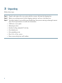
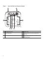
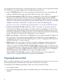
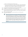
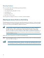
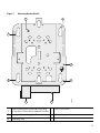
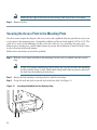
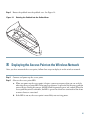
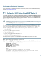
GETTING STARTED GUIDE
Cisco Aironet 3500 Series Lightweight Access Point
1
About this Guide
2
Safety Instructions
3
Unpacking
4
Overview
5
Configuring the Access Point
6
Mounting the Access Point
7
Securing the Access Point
8
Deploying the Access Point on the Wireless Network
9
Troubleshooting
10 Declarations of Conformity and Regulatory Information
11 Configuring DHCP Option 43 and DHCP Option 60
12 Access Point Specifications
1 About this Guide
This Guide provides instructions on how to install and configure your Cisco Aironet 3500 Series
Access Point. This guide also provides mounting instructions and limited troubleshooting procedures.
2 Safety Instructions
Translated versions of the following safety warnings are provided in the translated safety warnings
document that is shipped with your access point. The translated warnings are also in the Translated
Safety Warnings for Cisco Aironet Access Points, which is available on your documentation CD and
Cisco.com.
Warning
IMPORTANT SAFETY INSTRUCTIONS
This warning symbol means danger. You are in a situation that could cause bodily injury.
Before you work on any equipment, be aware of the hazards involved with electrical
circuitry and be familiar with standard practices for preventing accidents. Use the
statement number provided at the end of each warning to locate its translation in the
translated safety warnings that accompanied this device. Statement 1071
SAVE THESE INSTRUCTIONS
Warning
Read the installation instructions before you connect the system to its power source.
Statement 1004
Warning
This product must be connected to a Power-over-Ethernet (PoE) IEEE 802.3af compliant
power source or an IEC60950 compliant limited power source. Statement 353
Warning
Installation of the equipment must comply with local and national electrical codes.
Statement 1074
2
Warning
This product relies on the building’s installation for short-circuit (overcurrent)
protection. Ensure that the protective device is rated not greater than:
20A. Statement 1005
Warning
Do not operate your wireless network device near unshielded blasting caps or in an
explosive environment unless the device has been modified to be especially qualified for
such use. Statement 245B
Warning
In order to comply with FCC radio frequency (RF) exposure limits, antennas should be
located at a minimum of 7.9 inches (20 cm) or more from the body of all persons.
Statement 332
Caution
The fasteners you use to mount an access point on a ceiling must be capable of
maintaining a minimum pullout force of 20 lbs (9 kg) and must use all 4 indented holes
on the mounting bracket.
Caution
This product and all interconnected equipment must be installed indoors within the same
building, including the associated LAN connections as defined by Environment A of the
IEEE 802.af Standard.
Note
The access point is suitable for use in environmental air space in accordance with section
300.22.C of the National Electrical Code and sections 2-128, 12-010(3), and 12-100 of the
Canadian Electrical Code, Part 1, C22.1. You should not install the power supply or power
injector in air handling spaces.
Note
Use only with listed ITE equipment.
3
3 Unpacking
Follow these steps:
Step 1
Unpack and remove the access point and the accessory kit from the shipping box.
Step 2
Return any packing material to the shipping container and save it for future use.
Step 3
Verify that you have received the items listed below. If any item is missing or damaged, contact
your Cisco representative or reseller for instructions.
– 3500 series access point
– Mounting bracket
– Standard ceiling adjustable T-rail clip
– One thumbscrew
– One grounding screw
– Five 6-32 x 1/4 in. screws
– Four screws with plastic wall anchors
4
4 Overview
The following illustrations show the access point connections and features. The 3500e access point has
external antenna connectors; the 3500i access point has integrated antennas and does not have
external connectors.
Figure 1
Access Point Ports and Connections (top)
4
2
5
3
6
207613
1
1
2.4-GHz antenna connector B
(labelled with black text)
4
5-GHz antenna connector A
(labelled with blue text)
2
2.4-GHz antenna connector C
(labelled with black text)
5
5-GHz antenna connector C
(labelled with blue text)
3
2.4-GHz antenna connector A
(labelled with black text)
6
5-GHz antenna connector B
(labelled with blue text)
5
Figure 2
Access Point Ports and Connections (bottom)
1
5
6
272377
6
2
1
3
Kensington lock slot
4
4
Console port
5
Security padlock and hasp (padlock not
included)
Power connection
2
3
6
Ethernet port
6
Mounting bracket pins (feet for desk or
table-top mount)
5 Configuring the Access Point
This section describes how to connect the access point to a wireless LAN controller. Because the
configuration process takes place on the controller, see the Cisco Wireless LAN Controller
Configuration Guide for additional information. This guide is available on Cisco.com.
The Controller Discovery Process
The 3500 series access point uses the IETF standard Control and Provisioning of Wireless Access
Points Protocol (CAPWAP) to communicate between the controller and other wireless access points on
the network. CAPWAP is a standard, interoperable protocol which enables an access controller to
manage a collection of wireless termination points. The discovery process using CAPWAP is identical
to the Lightweight Access Point Protocol (LWAPP) used with previous Cisco Aironet access points.
LWAPP-enabled access points are compatible with CAPWAP and conversion to a CAPWAP controller
is seamless. Deployments can combine CAPWAP and LWAPP software on the controllers.
The functionality provided by the controller does not change except for customers who have Layer 2
deployments, which CAPWAP does not support.
In a CAPWAP environment, a wireless access point discovers a controller by using CAPWAP discovery
mechanisms and then sends it a CAPWAP join request. The controller sends the access point a
CAPWAP join response allowing the access point to join the controller. When the access point joins
the controller, the controller manages its configuration, firmware, control transactions, and data
transactions.
Note
For additional information about the discovery process and CAPWAP, see the Cisco Wireless
LAN Controller Software Configuration Guide. This document is available on Cisco.com.
Note
CAPWAP support is provided in controller software release 5.2 or later. However, your
controller must be running release 7.0 or later to support 3500 series access points.
Note
You cannot edit or query any access point using the controller CLI if the name of the access
point contains a space.
Note
Make sure that the controller is set to the current time. If the controller is set to a time that
has already occurred, the access point might not join the controller because its certificate may
not be valid for that time.
7
Access points must be discovered by a controller before they can become an active part of the network.
The 3500 series access point supports these controller discovery processes:
• Layer 3 CAPWAP discovery—Can occur on different subnets than the access point and uses IP
addresses and UDP packets rather than MAC addresses used by Layer 2 discovery.
• Over-the-air provisioning (OTAP)—This feature is supported by Cisco 4400 series controllers. If
this feature is enabled on the controller, all joined access points transmit wireless CAPWAP
neighbor messages, and new access points receive the controller IP address from these messages.
This feature is disabled by default and should remain disabled when all access points are installed.
Additional information about OTAP is available on Cisco.com at the following link:
http://www.ciscosystems.com/en/US/products/ps6366/products_tech_note09186a008093d74a.shtml
• Locally stored controller IP address discovery—If the access point was previously joined to a
controller, the IP addresses of the primary, secondary, and tertiary controllers are stored in the
access point’s non-volatile memory. This process of storing controller IP addresses on an access
point for later deployment is called priming the access point. For more information about priming,
see the “Performing a Pre-Installation Configuration” section on page 9.
• DHCP server discovery—This feature uses DHCP option 43 to provide controller IP addresses to
the access points. Cisco switches support a DHCP server option that is typically used for this
capability. For more information about DHCP option 43, see the “Configuring DHCP Option 43
and DHCP Option 60” section on page 43.
• DNS discovery—The access point can discover controllers through your domain name server
(DNS). For the access point to do so, you must configure your DNS to return controller IP
addresses in response to CISCO-LWAPP-CONTROLLER.localdomain, where localdomain is the
access point domain name. Configuring the CISCO-LWAPP-CONTROLLER provides backwards
compatibility in an existing customer deployment. When an access point receives an IP address
and DNS information from a DHCP server, it contacts the DNS to resolve
CISCO-LWAPP-CONTROLLER.localdomain. When the DNS sends a list of controller IP
addresses, the access point sends discovery requests to the controllers.
Preparing the Access Point
Before you mount and deploy your access point, we recommend that you perform a site survey (or use
the site planning tool) to determine the best location to install your access point.
You should have the following information about your wireless network available:
• Access point locations.
• Access point mounting options: below a suspended ceiling, on a flat horizontal surface, or on a
desktop.
8
Note
You can mount the access point above a suspended ceiling but you must purchase
additional mounting hardware: See “Mounting the Access Point” section on page 13 for
additional information.
• Access point power options: power supplied by the recommended external power supply (Cisco
AIR-PWR-B), a DC power supply, PoE from a network device, or a PoE power injector/hub
(usually located in a wiring closet).
Note
Access points mounted in a building’s environmental airspace must be powered using PoE
to comply with safety regulations.
Cisco recommends that you make a site map showing access point locations so that you can record the
device MAC addresses from each location and return them to the person who is planning or managing
your wireless network.
Installation Summary
Installing the access point involves these operations:
• Performing a pre-installation configuration (optional)
• Mounting the access point
• Grounding the access point
• Deploying the access point on the wireless network
Performing a Pre-Installation Configuration
The following procedures ensure that your access point installation and initial operation go as
expected. A pre-installation configuration is also known as priming the access point. This procedure
is optional.
Note
Performing a pre-installation configuration is an optional procedure. If your network
controller is properly configured, you can install your access point in its final location and
connect it to the network from there. See the “Deploying the Access Point on the Wireless
Network” section on page 25 for details.
9
Pre-Installation Configuration Setup
Figure 3 shows the pre-installation configuration setup.
Figure 3
Pre-Installation Configuration Setup
Controller
Layer 3
devices
272488
Cisco Aironet
access points
Follow these steps to perform the pre-installation configuration.
Step 1
Make sure that the Cisco wireless LAN controller DS port is connected to the network. Use
the CLI, web-browser interface, or Cisco WCS procedures as described in the appropriate
Cisco wireless LAN controller guide.
a. Make sure that access points have Layer 3 connectivity to the Cisco wireless LAN controller
Management and AP-Manager Interface.
b. Configure the switch to which your access point is to attach. See the Cisco Unified Wireless
Network WLAN Controller Guide: Cisco 440x Series WLAN Controllers for additional
information.
c. Set the Cisco wireless LAN controller as the master so that new access points always join with
it.
d. Make sure DHCP is enabled on the network. The access point must receive its IP address
through DHCP.
10
e. CAPWAP UDP ports must not be blocked in the network.
f. The access point must be able to find the IP address of the controller. This can be
accomplished using DHCP, DNS, or IP subnet broadcast. This guide describes the DHCP
method to convey the controller IP address. For other methods, refer to the product
documentation. See also the “Using DHCP Option 43” section on page 27 for more
information.
Step 2
Apply power to the access point:
a. The access point is 802.3af (15.4 W) compliant and can be powered by any of the following
802.3af compliant devices:
– 2106 controller
– WS-C3550, WS-C3560, and WS-C3750 switches
– C1880 switch
– 2600, 2610, 2611, 2621, 2650, and 2651 multiservice platforms
– 2610XM, 2611XM, 2621XM, 2650XM, 2651XM, and 2691 multiservice platforms
– 2811, 2821, and 2851 integrated services routers
– 3620, 3631-telco, 3640, and 3660 multiservice platforms
– 3725 and 3745 multiservice access routers
– 3825 and 3845 integrated services routers
The recommended external power supply for the access point is the Cisco AIR-PWR-B
power supply. The access point can also be powered by the following optional external
power sources:
– 1250 series access point power injector (AIR-PWRINJ4)
– Any 802.3af compliant power injector
Note
The 3500 series access point requires a Gigibit Ethernet link to prevent the Ethernet
port from becoming a bottleneck for traffic because wireless traffic speeds exceed
transmit speeds of a 10/100 Ethernet port.
b. As the access point attempts to connect to the controller, the LEDs cycle through a green, red,
and amber sequence, which can take up to 5 minutes.
Note
If the access point remains in this mode for more than five minutes, the access point is
unable to find the Master Cisco wireless LAN controller. Check the connection between
the access point and the Cisco wireless LAN controller and be sure that they are on the
same subnet.
11
c. If the access point shuts down, check the power source.
d. After the access point finds the Cisco wireless LAN controller, it attempts to download the
new operating system code if the access point code version differs from the Cisco wireless
LAN controller code version. While this is happening, the Status LED blinks dark blue.
e. If the operating system download is successful, the access point reboots.
Step 3
Configure the access point if required. Use the controller CLI, controller GUI, or Cisco WCS
to customize the access-point-specific 802.11n network settings.
Step 4
If the pre-installation configuration is successful, the Status LED is green indicating normal
operation. Disconnect the access point and mount it at the location at which you intend to
deploy it on the wireless network.
Step 5
If your access point does not indicate normal operation, turn it off and repeat the
pre-installation configuration.
Note
12
When you are installing a Layer 3 access point on a different subnet than the Cisco
wireless LAN controller, be sure that a DHCP server is reachable from the subnet on
which you will be installing the access point, and that the subnet has a route back to
the Cisco wireless LAN controller. Also be sure that the route back to the Cisco
wireless LAN controller has destination UDP ports 5246 and 5247 open for CAPWAP
communications. Ensure that the route back to the primary, secondary, and tertiary
wireless LAN controller allows IP packet fragments. Finally, be sure that if address
translation is used, that the access point and the Cisco wireless LAN controller have
a static 1-to-1 NAT to an outside address. (Port Address Translation is not
supported.)
6 Mounting the Access Point
This section describes how to mount the access point using its supplied mounting hardware. Use the
provided mounting bracket (See Figure 4) to mount the access point on any flat horizontal surface or
below a standard or recessed suspended ceiling. The mounting bracket is not necessary when mounting
the access point on a table or desk top.
Note
Caution
The integrated antenna design of the 3500i access point is designed for horizontal surfaces
(table top and ceiling installations). When mounted to such surfaces, the integrated antennas
produce the best antenna radiation pattern. For advanced features such as voice, location, and
rogue access point detection, ceiling mounting is strongly recommended. However, for smaller
areas such as conference rooms, kiosks, transportation, and hot-spot usage where the
customer is concerned primarily with data coverage and not advanced features, you can
mount the unit on a wall using wall anchors.
Do not use plastic wall anchors or the keyhole slots on the mounting bracket for ceiling
installations. When mounting the access point on a hard ceiling, use four fasteners
capable of maintaining a minimum pullout force of 20 lbs (9 kg).
You can use the standard mounting bracket for most indoor installations, including the following:
• Hard ceilings and wall surfaces
• T-rail ceiling systems with both offset and flat panels (with rail widths of 9/16th, 15/16th, and 1.5
inches)
• Network boxes and electrical boxes
• Above suspended ceilings using B-Line or Erico above-ceiling hardware (not included)
• On previously installed access point mounting systems for 1100, 1130, 1230, or 1240 series access
points
13
Standard Mounting Bracket Installed on the 3500 Series Access Point
207615
Figure 4
You can also mount the access point above a suspended ceiling or to a junction box using optional
low-profile brackets or adapter brackets that you can order from Cisco.
You use the optional low-profile bracket to mount the access point almost flush to the mounting
surface. Figure 5 shows the optional low-profile adapter bracket installed on the 3500 series access
point. You can use the low-profile bracket to mount the access point on T-rail ceiling systems (with
rail widths of 9/16th, 15/16th, and 1.5 inches) and on channel-rail ceiling systems.
You use the optional adapter bracket to mount the access point on suspended ceiling installations using
existing mounting hardware for the 1100, 1130, 1230, or 1240 series access points. Figure 6 shows
the optional adapter bracket.
14
Optional Low Profile Mounting Bracket Installed on the 3500 Series Access Point
Figure 6
Optional Adapter Bracket Installed on the 3500 Series Access Point
272384
272380
Figure 5
15
Mounting Hardware
The access point ships with the following mounting hardware:
• One mounting bracket
• One standard ceiling adjustable T-rail clip
• One thumbscrew
• One grounding screw
• Four 6-32 x 1/4 in. screws
The low-profile and adapter brackets are available as orderable options.
Mounting the Access Point on a Hard Ceiling
The following procedure describes the steps required to mount the access point on a ceiling constructed
of 3/4-in (19.05-mm) or thicker plywood using #8 fasteners. Procedures for other materials may differ
and you may need to provide additional, appropriate fasteners.
Note
The access point’s integrated antennas perform best when the access point is mounted on
horizontal surfaces such as a table top or ceiling. For advanced features such as voice,
location, and rogue access point detection, ceiling mounting is strongly recommended.
However, for smaller areas such as conference rooms, kiosks, transportation environments, or
hot-spot usage where data coverage is the primary concern, the unit may be wall mounted
using wall anchors or screws.
Follow these steps to mount the access point on a plywood ceiling.
Step 1
Caution
16
Use the mounting bracket as a template to mark the locations of the four indented mounting
holes. See callout 3 in Figure 7.
Be sure to mark all four locations. To ensure a safe and secure installation, make sure you
are using adequate fasteners and mount the access point using no less than four fasteners.
Figure 7
Mounting Bracket Details
1
2
2
3
2
5
207612
2
4
Bracket locking post (used when attaching
the bracket to a previously mounted bracket) 4
Cable access cover
1
2
Access point mounting keyholes
Security hasp
3
Grounding post
5
17
Step 2
Use a #29 drill (0.1360-in. [3.4772 mm]) bit to drill a pilot hole at the mounting hole locations
you marked.
Note
The pilot hole size varies according to the material and thickness you are fastening.
Cisco recommends that you test the material to determine the ideal hole size for your
mounting application.
Step 3
(Optional) Drill or cut a cable access hole near and below the location of the low-profile
mounting plate cable access cover large enough for the Ethernet cable, building ground wire,
and power cables.
Step 4
Pull approximately 9 inches of cable through the hole. Route the Ethernet and power cables
through the bracket before you attach the bracket to the ceiling. Route the cables through the
main cable access hole and then through the smaller access hole as shown in Figure 8.
Routing the Ethernet and Power Cables
207614
Figure 8
Step 5
Use the ground screw to attach the building ground wire to the mounting bracket. See the
“Grounding the Access Point” section on page 22 for general grounding instructions.
Step 6
Position the mounting plate mounting holes (with indents down) over the pilot holes.
Step 7
Insert a fastener into each mounting hole and tighten.
18
Step 8
Connect the Ethernet and power cables to the access point.
Step 9
Align the access point feet with the large part of the keyhole mounting slots on the mounting
plate. When positioned correctly, the cable access cover will fit inside the access point
connector bay.
Step 10 Gently slide the access point onto the mounting bracket keyhole slots until it clicks into place.
Mounting the Access Point Below a Suspended Ceiling
Follow these steps to mount the access point below a standard or recessed suspended ceiling. See
Figure 9.
Suspended Ceiling Mounting Details
272375
Figure 9
1
2
5
3
4
1
Access point mounting keyhole
4
Access point cable access cover
2
Adjustable T-rail clip
5
Ceiling T-rail
3
Grounding point
19
Follow these steps to mount the access point below a suspended ceiling.
Step 1
Decide where you want to mount the access point on your suspended ceiling.
Step 2
Open the T-rail mounting clip completely. See Figure 10.
Figure 10
Adjustable T-Rail Clip
1
2
2
3
C
15
24
C
9/16
B
B
15
9/16
15/16
24
15/16
38
MM
INCH 1-1/2
CEILING
GRID
A
WIDTH
38
MM
INCH 1-1/2
CEILING
GRID
A
WIDTH
3
2
121758
2
1
1
T-rail locking screws
2
Mounting plate screw holes
3
T-rail width detents (A, B, or C)
Step 3
Place the T-rail clip over the T-rail and close it to the appropriate detent (A, B, or C).
Step 4
Use a screwdriver to tighten the two T-rail locking screws to prevent the T-rail clip from
sliding along the T-rail.
Step 5
Observe the T-rail width detent letter (A, B, or C) that corresponds to the T-rail width.
Step 6
Align the corresponding holes (A, B, or C) on the mounting plate over the T-rail mounting
plate holes.
20
Step 7
Hold the mounting bracket and insert a 6-32 x 1/4 in. screw into each of the four
corresponding holes (A, B, or C) and tighten.
Step 8
If necessary, drill or cut a cable access hole in the ceiling tile large enough for the Ethernet and
power cables. Pull the cables through the access hole until you have about 1 foot of cable
protruding from the hole.
Step 9
(Optional)—Use the ground screw to ground the access point to a suitable building ground.
See the “Grounding the Access Point” section on page 22 for general grounding instructions.
Step 10 Connect the Ethernet and power cables to the access point.
Step 11 Align the access point feet over the keyhole mounting slots on the mounting plate. If you
created a hole for the cables, make sure the access point is positioned so that the cables reach
their respective ports.
Step 12 Gently slide the access point onto the low-profile mounting bracket until it clicks into place.
21
Grounding the Access Point
Grounding is not always required for indoor installations because the 3500 series access point is
classified as a low-voltage device and does not contain an internal power supply. However, Ciso
recommends that you check your local and national electrical codes to see if grounding is a
requirement. If grounding is required in your area or you wish to ground your access point, follow
these steps.
Step 1
Find a suitable building grounding point as close to the access point as possible.
Step 2
Connect a user-supplied ground wire to the building grounding point. The wire should be a
minimum of #14AWG assuming a circuit length of 25 ft (30.5 cm). Consult your local
electrical codes for additional information.
Step 3
Route the ground wire to the access point.
Step 4
Attach the wire to a suitable grounding O-ring lug.
Step 5
Crimp or solder the wire to the lug.
Step 6
Insert the grounding post screw into the O-ring lug and install it on the mounting bracket as
shown in Figure 11.
Installing the O-Ring Lug to the Grounding Post
272428
Figure 11
Step 7
22
Use a Phillips screwdriver to tighten the ground screw.
7 Securing the Access Point
There are two ways to secure your access point:
• Attach it to an immovable object with a security cable.
• Lock it to the mounting plate with a padlock.
Using a Security Cable
You can secure the access point by installing a standard security cable (such as the Kensington Notebook
MicroSaver, model number 64068) into the access point security cable slot as shown in Figure 12.
Security Cable Details
272379
Figure 12
The security cable can be used with any of the mounting methods described in this guide.
Follow these steps to install the security cable.
Step 1
Loop the security cable around a nearby immovable object.
Step 2
Insert the key into the security cable lock.
Step 3
Insert the security cable latch into the security cable slot on the access point.
23
Note
Step 4
Rotate the key right or left to secure the security cable lock to the access point.
Remove the key.
Securing the Access Point to the Mounting Plate
Use the security hasp on the adapter cable access cover and a padlock (that you provide) to secure your
access point to the mounting plate. Compatible padlocks are Master Lock models 120T or 121T. The
cable access cover on the mounting bracket covers the cable bay area (including the power port,
Ethernet port, console port, and the mode button) to prevent the installation or removal of the cables
or the activation of the mode button.
Follow these instructions to install the padlock:
Step 1
With the access point installed on the mounting bracket, insert a padlock into the security
hasp.
Note
If your access point is mounted to a hard ceiling, the clearance between the mounting
bracket and the ceiling is small. Work slowly using both hands to position and secure
the lock into the mounting bracket hasp.
Step 2
Rotate the lock clockwise and align the bail with the lock body.
Step 3
Grasp the lock and push it into the bail to lock the lock. See Figure 13.
Inserting the Padlock into the Security Hasp
272382
Figure 13
24
Step 4
Rotate the padlock into the padlock area. See Figure 14.
Rotating the Padlock into the Padlock Area
272383
Figure 14
8 Deploying the Access Point on the Wireless Network
After you have mounted the access point, follow these steps to deploy it on the wireless network.
Step 1
Connect and power up the access point.
Step 2
Observe the access point LED.
a. When you power up the access point, it begins a power-up sequence that you can verify by
observing the access point LED. If the power-up sequence is successful, the discovery and join
process begins. During this process, the LED blinks sequentially green, red, and off. When the
access point has joined a controller, the LED is green if no clients are associated or blue if one
or more clients are associated.
b. If the LED is not on, the access point is most likely not receiving power.
25
c. If the LED blinks sequentially for more than 5 minutes, the access point is unable to find its
primary, secondary, and tertiary Cisco wireless LAN controller. Check the connection
between the access point and the Cisco wireless LAN controller, and be sure the access point
and the Cisco wireless LAN controller are either on the same subnet or that the access point
has a route back to its primary, secondary, and tertiary Cisco wireless LAN controller. Also,
if the access point is not on the same subnet as the Cisco wireless LAN controller, be sure that
there is a properly configured DHCP server on the same subnet as the access point. See the
“Configuring DHCP Option 43 and DHCP Option 60” section on page 43 for additional
information.
Step 3
Reconfigure the Cisco wireless LAN controller so that it is not the Master.
Note
A Master Cisco wireless LAN controller should be used only for configuring access
points and not in a working network.
9 Troubleshooting
If you experience difficulty getting your access point installed and running, look for a solution to your
problem in this guide or in additional access point documentation. These, and other documents, are
available on Cisco.com.
Guidelines for Using Cisco Aironet Lightweight Access Points
Keep these guidelines in mind when you use 3500 series lightweight access points:
• The access point can only communicate with Cisco wireless LAN controllers, such as 2100, 4400,
and 5500 series controllers.
• The access point does not support Wireless Domain Services (WDS) and cannot communicate with
WDS devices. However, the controller provides functionality equivalent to WDS when the access
point joins it.
• CAPWAP does not support Layer 2. The access point must get an IP address and discover the
controller using Layer 3, DHCP, DNS, or IP subnet broadcast.
• The access point console port is enabled for monitoring and debug purposes. All configuration
commands are disabled when the access point is connected to a controller.
26
Using DHCP Option 43
You can use DHCP Option 43 to provide a list of controller IP addresses to the access points, enabling
them to find and join a controller. For additional information, refer to the “Configuring DHCP Option
43 and DHCP Option 60” section on page 43.
Checking the Access Point LED
Figure 15 shows the location of the access point Status LED.
Figure 15
Access Point LED Location
272378
1
1
Status LED
27
Table 1 shows the access point Status LED indications for various conditions.
Table 1
LED Status Indications
Message
Type
Status
LED
Message
Meaning
Boot loader status
sequence
Blinking green
DRAM memory test in progress
DRAM memory test OK
Board initialization in progress
Initializing FLASH file system
FLASH memory test OK
Initializing Ethernet
Ethernet OK
Starting Cisco IOS
Initialization successful
Association status
Operating status
Boot loader warnings
28
Green
Normal operating condition, but no wireless
client associated
Blue
Normal operating condition, at least one wireless
client association
Blinking blue
Software upgrade in progress
Cycling through green,
red, and off
Discovery/join process in progress
Rapidly cycling
through blue, green,
and red
Access point location command invoked
Blinking red
Ethernet link not operational
Blinking blue
Configuration recovery in progress (MODE
button pushed for 2 to 3 seconds)
Red
Ethernet failure or image recovery (MODE
button pushed for 20 to 30 seconds)
Blinking green
Image recovery in progress (MODE button
released)
Table 1
LED Status Indications (continued)
Message
Type
Status
LED
Message
Meaning
Boot loader errors
Red
DRAM memory test failure
Blinking red and blue
FLASH file system failure
Blinking red and off
Environment variable failure
Bad MAC address
Ethernet failure during image recovery
Boot environment failure
No Cisco image file
Boot failure
Cisco IOS errors
Red
Software failure; try disconnecting and
reconnecting unit power
Cycling through blue,
green, red, and off
General warning; insufficient inline power
Troubleshooting the Access Point Join Process
Access points can fail to join a controller for many reasons: a RADIUS authorization is pending;
self-signed certificates are not enabled on the controller; the access point’s and controller’s regulatory
domains don’t match, and so on.
Controller software enables you to configure the access points to send all CAPWAP-related errors to
a syslog server. You do not need to enable any debug commands on the controller because all of the
CAPWAP error messages can be viewed from the syslog server itself.
The state of the access point is not maintained on the controller until it receives a CAPWAP join
request from the access point. Therefore, it can be difficult to determine why the CAPWAP discovery
request from a certain access point was rejected. In order to troubleshoot such joining problems
without enabling CAPWAP debug commands on the controller, the controller collects information for
all access points that send a discovery message to it and maintains information for any access points
that have successfully joined it.
The controller collects all join-related information for each access point that sends a CAPWAP
discovery request to the controller. Collection begins with the first discovery message received from
the access point and ends with the last configuration payload sent from the controller to the access
point.
29
You can view join-related information for the following numbers of access points:
• Up to 300 access points for 4400 series controllers, the Cisco WiSM, and the Catalyst 3750G
Integrated Wireless LAN Controller Switch
• Up to three times the maximum number of access points supported by the platform for the 2100
series controllers and the Controller Network Module within the Cisco 28/37/38xx Series
Integrated Services Routers
When the controller is maintaining join-related information for the maximum number of access points,
it does not collect information for any more access points.
An access point sends all syslog messages to IP address 255.255.255.255 by default when any of the
following conditions are met:
• An access point running software release 5.2 or later has been newly deployed.
• An existing access point running software release 5.2 or later has been reset after clearing the
configuration.
If any of these conditions are met and the access point has not yet joined a controller, you can also
configure a DHCP server to return a syslog server IP address to the access point using option 7 on the
server. The access point then starts sending all syslog messages to this IP address.
When the access point joins a controller for the first time, the controller sends the global syslog server
IP address (the default is 255.255.255.255) to the access point. After that, the access point sends all
syslog messages to this IP address until it is overridden by one of the following scenarios:
• The access point is still connected to the same controller, and the global syslog server IP address
configuration on the controller has been changed using the config ap syslog host global
syslog_server_IP_address command. In this case, the controller sends the new global syslog server
IP address to the access point.
• The access point is still connected to the same controller, and a specific syslog server IP address
has been configured for the access point on the controller using the config ap syslog host specific
Cisco_AP syslog_server_IP_address command. In this case, the controller sends the new specific
syslog server IP address to the access point.
• The access point is disconnected from the controller and joins another controller. In this case, the
new controller sends its global syslog server IP address to the access point.
• Whenever a new syslog server IP address overrides the existing syslog server IP address, the old
address is erased from persistent storage, and the new address is stored in its place. The access
point also starts sending all syslog messages to the new IP address provided the access point can
reach the syslog server IP address.
You can configure the syslog server for access points and view the access point join information only
from the controller CLI.
A detailed explanation of the join process is on Cisco.com at the following URL:
http://www.Cisco.com/en/US/products/ps6366/products_tech_note09186a00808f8599.shtml
30
10 Declarations of Conformity and Regulatory Information
This section provides declarations of conformity and regulatory information for the Cisco Aironet
3500 Series Access Point.
Manufacturers Federal Communication Commission Declaration of
Conformity Statement
Tested To Comply
With FCC Standards
FOR HOME OR OFFICE USE
Models
Certification Numbers
AIR-CAP3501E-A-K9
AIR-CAP3501I-A-K9
LDK102072
AIR-CAP3502I-A-K9
AIR-CAP3502E-A-K9
LDK102073
Manufacturer:
Cisco Systems, Inc.
170 West Tasman Drive
San Jose, CA 95134-1706
USA
This device complies with Part 15 rules. Operation is subject to the following two conditions:
1. This device may not cause harmful interference, and
2. This device must accept any interference received, including interference that may cause undesired
operation.
This device operates in the 5150-5250MHz and 5470-5725MHz bands and is therefore restricted to
indoor operation only per FCC guidance.
31
This equipment has been tested and found to comply with the limits of a Class B digital device,
pursuant to Part 15 of the FCC Rules. These limits are designed to provide reasonable protection
against harmful interference when the equipment is operated in a residential environment. This
equipment generates, uses, and radiates radio frequency energy, and if not installed and used in
accordance with the instructions, may cause harmful interference. However, there is no guarantee that
interference will not occur. If this equipment does cause interference to radio or television reception,
which can be determined by turning the equipment off and on, the user is encouraged to correct the
interference by one of the following measures:
• Reorient or relocate the receiving antenna.
• Increase separation between the equipment and receiver.
• Connect the equipment to an outlet on a circuit different from which the receiver is connected.
• Consult the dealer or an experienced radio/TV technician.
Caution
The Part 15 radio device operates on a non-interference basis with other devices operating
at this frequency when using the integrated antennas. Any changes or modification to the
product not expressly approved by Cisco could void the user’s authority to operate this
device.
Caution
Within the 5.15 to 5.25 GHz and 5.47-5.725 GHz bands, this device is restricted to
indoor operations to reduce any potential for harmful interference to co-channel Mobile
Satellite System (MSS) operations.
32
VCCI Statement for Japan
Warning
This is a Class B product based on the standard of the Voluntary Control
Council for Interference from Information Technology Equipment (VCCI). If this
is used near a radio or television receiver in a domestic environment, it may
cause radio interference. Install and use the equipment according to the
instruction manual.
Guidelines for Operating Cisco Aironet Access Points in Japan
This section provides guidelines for avoiding interference when operating Cisco Aironet access points
in Japan. These guidelines are provided in both Japanese and English.
33
03-6434-6500
43768
Japanese Translation
English Translation
This equipment operates in the same frequency bandwidth as industrial, scientific, and medical devices
such as microwave ovens and mobile object identification (RF-ID) systems (licensed premises radio
stations and unlicensed specified low-power radio stations) used in factory production lines.
1. Before using this equipment, make sure that no premises radio stations or specified low-power
radio stations of RF-ID are used in the vicinity.
2. If this equipment causes RF interference to a premises radio station of RF-ID, promptly change
the frequency or stop using the device; contact the number below and ask for recommendations
on avoiding radio interference, such as setting partitions.
3. If this equipment causes RF interference to a specified low-power radio station of RF-ID, contact
the number below.
Contact Number: 03-6434-6500
34
Statement 371—Power Cable and AC Adapter
English Translation
When installing the product, please use the provided or designated connection cables/power cables/AC
adaptors. Using any other cables/adaptors could cause a malfunction or a fire. Electrical Appliance and
Material Safety Law prohibits the use of UL-certified cables (that have the “UL” shown on the code)
for any other electrical devices than products designated by CISCO. The use of cables that are certified
by Electrical Appliance and Material Safety Law (that have “PSE” shown on the code) is not limited
to CISCO-designated products.
Industry Canada
Canadian Compliance Statement
AIR-CAP3501E-A-K9
AIR-CAP3501I-A-K9
2461B-102072
AIR-CAP3502E-A-K9
AIR-CAP3502I-A-K9
2461B-102073
This Class B Digital apparatus meets all the requirements of the Canadian Interference-Causing
Equipment Regulations.
Cet appareil numerique de la classe B respecte les exigences du Reglement sur le material broilleur du
Canada.
This device complies with Class B Limits of Industry Canada. Operation is subject to the following
two conditions:
1. This device may not cause harmful interference, and
35
2. This device must accept any interference received, including interference that may cause undesired
operation.
Cisco Aironet Access Points are certified to the requirements of RSS-210. The use of this device in a
system operating either partially or completely outdoors may require the user to obtain a license for
the system according to the Canadian regulations. For further information, contact your local Industry
Canada office.
This device has been designed to operate with antennas having a maximum gain of 6 dBi. Antennas
having a gain greater than 6 dBi are strictly prohibited for use with this device. The required antenna
impedance is 50 ohms.
To reduce potential radio interference to other users, the antenna type and its gain should be so chosen
that the equivalent isotropically radiated power (EIRP) is not more than that permitted for successful
communication.
European Community, Switzerland, Norway, Iceland, and
Liechtenstein
Models:
AIR-CAP3501E-E-K9
AIR-CAP3502E-E-K9
AIR-CAP3501I-E-K9
AIR-CAP3502I-E-K9
36
Declaration of Conformity with regard to the R&TTE Directive
1999/5/EC & Medical Directive 93/42/EEC
37
The following standards were applied:
EMC—EN 301.489-1 v1.4.1; EN 301.489-17 v1.2.1
Health & Safety—EN60950-1: 2001; EN 50385: 2002
Radio—EN 300 328 v 1.7.1; EN 301.893 v 1.5.1
The conformity assessment procedure referred to in Article 10.4 and Annex III of Directive 1999/5/EC
has been followed.
38
This device also conforms to the EMC requirements of the Medical Devices Directive 93/42/EEC.
Note
This equipment is intended to be used in all EU and EFTA countries. Outdoor use may be
restricted to certain frequencies and/or may require a license for operation. For more details,
contact Cisco Corporate Compliance.
The product carries the CE Mark:
Declaration of Conformity for RF Exposure
United States
This system has been evaluated for RF exposure for Humans in reference to ANSI C 95.1 (American
National Standards Institute) limits. The evaluation was based on ANSI C 95.1 and FCC OET Bulletin
65C rev 01.01. The minimum separation distance from the antenna to general bystander is 7.9 inches
(20cm) to maintain compliance.
Canada
This system has been evaluated for RF exposure for Humans in reference to ANSI C 95.1 (American
National Standards Institute) limits. The evaluation was based on RSS-102 Rev 2. The minimum
separation distance from the antenna to general bystander is 7.9 inches (20cm) to maintain
compliance.
European Union
This system has been evaluated for RF exposure for Humans in reference to the ICNIRP (International
Commission on Non-Ionizing Radiation Protection) limits. The evaluation was based on the EN
50385 Product Standard to Demonstrate Compliance of Radio Base stations and Fixed Terminals for
Wireless Telecommunications Systems with basic restrictions or reference levels related to Human
Exposure to Radio Frequency Electromagnetic Fields from 300 MHz to 40 GHz. The minimum
separation distance from the antenna to general bystander is 20cm (7.9 inches).
39
Australia
This system has been evaluated for RF exposure for Humans as referenced in the Australian Radiation
Protection standard and has been evaluated to the ICNIRP (International Commission on
Non-Ionizing Radiation Protection) limits. The minimum separation distance from the antenna to
general bystander is 20cm (7.9 inches).
Administrative Rules for Cisco Aironet Access Points in Taiwan
This section provides administrative rules for operating Cisco Aironet access points in Taiwan. The
rules for all access points are provided in both Chinese and English.
Chinese Translation
40
English Translation
Administrative Rules for Low-power Radio-Frequency Devices
Article 12
For those low-power radio-frequency devices that have already received a type-approval, companies,
business units or users should not change its frequencies, increase its power or change its original
features and functions.
Article 14
The operation of the low-power radio-frequency devices is subject to the conditions that no harmful
interference is caused to aviation safety and authorized radio station; and if interference is caused, the
user must stop operating the device immediately and can't re-operate it until the harmful interference
is clear.
The authorized radio station means a radio-communication service operating in accordance with the
Communication Act.
The operation of the low-power radio-frequency devices is subject to the interference caused by the
operation of an authorized radio station, by another intentional or unintentional radiator, by
industrial, scientific and medical (ISM) equipment, or by an incidental radiator.
Chinese Translation
41
English Translation
Low-power Radio-frequency Devices Technical Specifications
4.7
Unlicensed National Information Infrastructure
4.7.5
Within the 5.25-5.35 GHz band, U-NII devices will be restricted to indoor operations to
reduce any potential for harmful interference to co-channel MSS operations.
4.7.6
The U-NII devices shall accept any interference from legal communications and shall not
interfere the legal communications. If interference is caused, the user must stop operating
the device immediately and can't re-operate it until the harmful interference is clear.
4.7.7
Manufacturers of U-NII devices are responsible for ensuring frequency stability such that
an emission is maintained within the band of operation under all conditions of normal
operation as specified in the user manual.
Operation of Cisco Aironet Access Points in Brazil
This section contains special information for operation of Cisco Aironet access points in Brazil.
Access Point Models
AIR-CAP3501E-A-K9
AIR-CAP3501I-A-K9
AIR-CAP3502E-T-K9
AIR-CAP3502I-T-K9
Portuguese Translation
Este equipamento opera em caráter secundário, isto é, não tem direito a proteção contra interferência
prejudicial, mesmo de estações do mesmo tipo, e não pode causar interferência a sistemas operando
em caráter primário.
English Translation
This equipment operates on a secondary basis and consequently must accept harmful interference,
including interference from stations of the same kind. This equipment may not cause harmful
interference to systems operating on a primary basis.
42
Declaration of Conformity Statements
All the Declaration of Conformity statements related to this product can be found at the following
location: http://www.ciscofax.com
11 Configuring DHCP Option 43 and DHCP Option 60
This section contains a DHCP Option 43 configuration example on a Windows 2003 Enterprise DHCP
server for use with Cisco Aironet lightweight access points. For other DHCP server implementations,
consult product documentation for configuring DHCP Option 43. In Option 43, you should use the
IP address of the controller management interface.
Note
DHCP Option 43 is limited to one access point type per DHCP pool. You must configure a
separate DHCP pool for each access point type.
The 3500 series access point uses the type-length-value (TLV) format for DHCP Option 43. DHCP
servers must be programmed to return the option based on the access point’s DHCP Vendor Class
Identifier (VCI) string (DHCP Option 60). The VCI string for the 3500 series access point is:
Cisco AP c3500
The format of the TLV block is listed below:
• Type: 0xf1 (decimal 241)
• Length: Number of controller IP addresses * 4
• Value: List of WLC management interfaces
To configure DHCP Option 43 in the embedded Cisco IOS DHCP server, follow these steps:
Step 1
Enter configuration mode at the Cisco IOS CLI.
Step 2
Create the DHCP pool, including the necessary parameters such as default router and name
server. A DHCP scope example is as follows:
ip dhcp pool <pool name>
network <IP Network> <Netmask>
default-router <Default router>
dns-server <DNS Server>
Where:
<pool name> is the name of the DHCP pool, such as AP3500
<IP Network> is the network IP address where the controller resides, such as
10.0.15.1
<Netmask> is the subnet mask, such as 255.255.255.0
43
<Default router> is the IP address of the default router, such as 10.0.0.1
<DNS Server> is the IP address of the DNS server, such as 10.0.10.2
Step 3
Add the option 60 line using the following syntax:
option 60 ascii “VCI string”
For the VCI string, “Cisco AP c3500”. The quotation marks must be included.
Step 4
Add the option 43 line using the following syntax:
option 43 hex <hex string>
The hex string is assembled by concatenating the TLV values shown below:
Type + Length + Value
Type is always f1(hex). Length is the number of controller management IP addresses times 4
in hex. Value is the IP address of the controller listed sequentially in hex.
For example, suppose that there are two controllers with management interface IP addresses,
10.126.126.2 and 10.127.127.2. The type is f1(hex). The length is 2 * 4 = 8 = 08 (hex). The IP
addresses translate to 0a7e7e02 and 0a7f7f02. Assembling the string then yields
f1080a7e7e020a7f7f02. The resulting Cisco IOS command added to the DHCP scope is option 43 hex
f1080a7e7e020a7f7f02.
44
12 Access Point Specifications
Table 2 lists the technical specifications for 3500 series access points.
Table 2
Access Point Specifications
Category
Specification
Dimensions (LxWxD)
8.68 x 8.68 x 1.84 in. (22.04 x 22.04 x 4.67 cm)
Weight
1.9 lbs (0.86 kg)
Operating temperatures AP3500e: -4 to 131 degrees F (-20 to 55 degrees C)
AP3500i: 32 to 104 degrees F (0 to 40 degrees C)
Storage temperature
–22 to 185 degrees F (–30 to 85 degrees C)
Humidity
10% to 90% (noncondensing)
Antennas
AP3500i: Integrated; AP3500e: External
Compliance
The 3500 series access point complies with UL 2043 for products installed
in a building’s environmental air handling spaces, such as above suspended
ceilings.
Safety
UL 60950-1
CAN/CSA C22.2 No. 60950-1
IEC 60950-1 with all national deviations
EN 60950-1
UL 2043
EMI and Susceptibility
FCC Part 15.107 and 15.109 Class B
ICES-003 Class B (Canada)
EN 301.489
EN 55022 Class B, 2000 version
EN 55024
VCCI Class B
Radio
FCC Part 15.247, 15.407
Canada RSS-210
Japan Telec 33, 66, T71
EN 330.328, EN 301.893
FCC Bulletin OET-65C
Industry Canada RSS-102
Maximum power and
channel settings
Maximum power and the channels allowed in your regulatory domain,
refer to Channels and Maximum Power Settings for Cisco Aironet
Lightweight Access Points. This document is available on Cisco.com.
45
46
47
Americas Headquarters
Cisco Systems, Inc.
170 West Tasman Drive
San Jose, CA 95134-1706
USA
www.cisco.com
Tel: 408 526-4000
800 553-NETS (6387)
Fax: 408 527-0883
Asia Pacific Headquarters
Cisco Systems (USA) Pte. Ltd.
168 Robinson Road
#28-01 Capital Tower
Singapore 068912
www.cisco.com
Tel: +65 6317 7777
Fax: +65 6317 7799
Europe Headquarters
Cisco Systems International BV
Haarlerbergpark
Haarlerbergweg 13-19
1101 CH Amsterdam
The Netherlands
www-europe.cisco.com
Tel: 31 0 800 020 0791
Fax: 31 0 20 357 1100
Cisco has more than 200 offices worldwide. Addresses, phone numbers, and fax numbers are listed on the
Cisco Website at www.cisco.com/go/offices.
CCDE, CCENT, Cisco Eos, Cisco Lumin, Cisco Nexus, Cisco StadiumVision, Cisco TelePresence, Cisco WebEx, the Cisco logo, DCE,
and Welcome to the Human Network are trademarks; Changing the Way We Work, Live, Play, and Learn and Cisco Store are service
marks; and Access Registrar, Aironet, AsyncOS, Bringing the Meeting To You, Catalyst, CCDA, CCDP, CCIE, CCIP, CCNA, CCNP,
CCSP, CCVP, Cisco, the Cisco Certified Internetwork Expert logo, Cisco IOS, Cisco Press, Cisco Systems, Cisco Systems Capital, the
Cisco Systems logo, Cisco Unity, Collaboration Without Limitation, EtherFast, EtherSwitch, Event Center, Fast Step, Follow Me
Browsing, FormShare, GigaDrive, HomeLink, Internet Quotient, IOS, iPhone, iQuick Study, IronPort, the IronPort logo, LightStream,
Linksys, MediaTone, MeetingPlace, MeetingPlace Chime Sound, MGX, Networkers, Networking Academy, Network Registrar,
PCNow, PIX, PowerPanels, ProConnect, ScriptShare, SenderBase, SMARTnet, Spectrum Expert, StackWise, The Fastest Way to
Increase Your Internet Quotient, TransPath, WebEx, and the WebEx logo are registered trademarks of Cisco Systems, Inc. and/or its
affiliates in the United States and certain other countries.
All other trademarks mentioned in this document or website are the property of their respective owners. The use of the word partner does
not imply a partnership relationship between Cisco and any other company. (0809R)
© 2010 Cisco Systems, Inc. All rights reserved.
Printed in the USA on recycled paper containing 10% postconsumer waste.