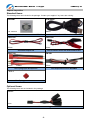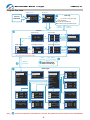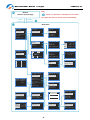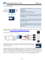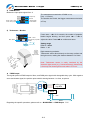
1
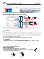
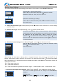
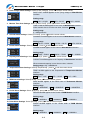
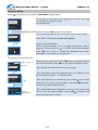
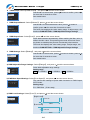
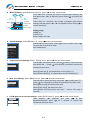
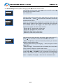
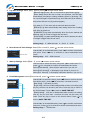
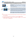
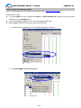
Multifunctional Monitor & Logger PowerLog 6S Thank you for purchasing the PowerLog 6S. Please read the User‘s Manual completely and attentively as it contains lots of specific operations and safety information. PowerLog 6S is one compact multifunctional monitoring and logging meter, adopting 32 bit ARM processor, with 12 bit A/D convertor to ensure the accurate measurement. Specifications Input voltage range: Current measurement range: Cell voltage range: External temperature measurement range: Pulse measurement range: Pulse width output range: Tachometer measurement range: Voltage resolution / accuracy: Current resolution / accuracy: Current loading of test: Maximum voltage for alarm port: Current drain for alarm port: Log files storage: Sample logging time interval: PC connect: Weight: Dimensions (L X W X D): 4.5 – 60.0VDC -130A – +130A(continuance -40A – +40A) 0.05 – 28.0VDC -55℃– +125℃ (-67 oF–+257 oF) 10us–999999us 0–20ms (0.5us step) 0–99999 RPM 0.001V / 0.5% 0.01A / 5% 12mA 50VDC <500mA 16Mbit (33 hours@2 seconds logging interval) 0.25 – 3600 seconds USB port 29g 85X40X13mm (3.34‖X1.57‖X0.51‖) Special features PowerLog 6S allows bidirectional current sensing, adopting 0.2 mΩ current sampling resistor with low insertion loss. 1 channel 0-60V voltage measurement. 6 channels cells voltage measurement (can not only measure 1-6S Li/ NiMH/NiCd/ Pb battery individual voltage, but also measure 6 channels 0.05-28V voltage) 4 channels temperature measurement (1 channel internal temperature measurement and 3 channels external temperature measurement) Propeller RPM measurement, adopting non-contact optical sensing, user settable blade number. PWM signal measurement: frequency, period, pulse width, duty cycle. Applicable to remote control channel signal, measure, and monitor. PWM output: manual and auto mode, auto mode is able to break in servos, electronic speed controllers, R/C switches etc. Motor KV measurement. The 2-wire mode is suitable for the KV measurement of brushless motor; while 3-wire mode is suitable for the KV measurement of both brushed and brushless motors. Small size with multiple functions, backlight 128*64 lattices LCD and Buzzer Tone Reminder; the interface can be operated smoothly. It can be set Cells Voltage/Pack Voltage/Timer Over/Current/Power/Capacity/Temperature/RPM/Period and Pulse Alarm. What‘s more, the extra alarm output can be linkage controlled by the users. It has 8 sets default monitor alarm settings, which can be selected for different battery packs. PowerLog 6S has been 100% calibrated before it enters to the market, at the same time, it supports the calibration by users themselves. The logging interval can be set by users‘ different needs. PowerLog 6S has a 16Mbit flash storage, which can log offline data in 33 hours @2 seconds logging interval. Support upgrading the hardware program by USB port. Adopting HID protocol, dispense with installing driver from PC, plug and play. The PowerLog 6S supports the ―Logview‖ software and can display, plot and analyze the data by it. (See detail information about Logview in the following website: http://www.logview.info) -2- Multifunctional Monitor & Logger PowerLog 6S Unpack inspection Standard items: The following items are included in the package. Contact your supplier if any items are missing. CW-USB5 CDROM 80mm 85 X 85mm One copy of the User’s manual on CDROM One Mini-USB data line CW-P220 CW-C220 20mm 20mm One Alarm output line One brushless motor KV measurements line TW-JR1 CW-T210 10mm 35mm 12AWG One T-plug input & output line One temperature sensor DS18B20 TPC-1 Two T-plug protection cover Optional items: The following items are not included in the package. TJR-13 5mm JR connector 1-3 -3- Multifunctional Monitor & Logger PowerLog 6S External controls and connections ⑴ ⑷ ⑵ ⑺ ⑸ ⑻ ⑹ ⑼ ⑶ ⑾ ⑽ 1. Beep 2. Input T-plug(T1) 5. LCD screen 6. Buttons 9. Multiple Voltage Input Port(J3) 3. Output T-plug (T2) 7. Pulse I/O (J1) 10. Alarm Port 4. Tachometer Sensor 8. Temperature Sensor Port (J2) 11. USB Port PowerLog 6S Connection Diagram S+- J1 J2 1 1 2 2 3 3 Temperature sensor or 5V Power Pulse Input /PWM Output + (4.5-60V) POWER + charger RPM I/P +OUT- --- -IN+ BATT. PACK ALM TYPE HOLD MENU + 6 5 4 3 2 1 - s+- Measures RPM Measures motor KV Brushless/Brushed motor PIN 1 USB 1 2 3 4 5 6 OR LOAD ESC + PIN 7 1S + 2S + 3S + 4S + 5S - 6S + + Alarm Computer -4- Multifunctional Monitor & Logger PowerLog 6S Program flow chart Logo Screen Inf. Screen S/N:XXXXXXXXXX PowerLog6S Ver X.X.X www.hillrc.com PowerLog POWER ON TYPE XXXXXXXXXX LOGS 0 RATE2.00S [1988Kb/16h:34] Logs OFF ④ Data Log “____” is shown in the upper right corner blinkingly Transfer data to USB port Save data to the appointed Log File <HOLD> >3 Seconds <HOLD> >3 Seconds Monitor ① Watt monitor Cells monitor 5S20.63V▣V 75mV <▢>+<▼> < > 1 4.110V2 4.152V >3 Seconds 10.50A 34.087V44.162V 5 4.120V6 ------ <MENU> 12.01V 126.1W >3 Seconds < > Tachometer monitor Temperature monitor 003015mAh 20m:10 < > < > PWM monitor Freq. 50Hz Period 20000us +P 5.0% 1000us -P95.0% 19000us ------ < > TACHOMETER RPM T028.7C28.5 < > T127.1C25.8 T227.1C27.1 T3NULLCNULL 1200 Max01250Blade03 CELLS MODE ⊙Difference ○Auto Differenc ○Each Voltage 28.9 <▢>+<▼> >3 Seconds 30.7 32.5 NULL <MENU> >3 Seconds TEMP SENSOR LIST 00000297e2D6 00000297d187 <not used> Note: When you turn off the PowerLog6S it will remember the current screen and start from that screen when next turned on again. <TYPE> >3 Seconds ③ <MENU> >3 Seconds ② ⊙LiPo ○Lilo ○LiFe ○User1 ○User2 ○User3 ○User4 ○User5 POWER ALARM MAX. 7800W MIN. -7800W DIFF 15600W CAPACITY ALARM (100-999900mAh) 999900 Select Main Menu Details in next page Select Type SELECT TYPE Note: <MENU> >3 Seconds LiPo ALARM SETTING Select Rename Alarm&Trigger Cells Voltag Pack Voltage Timer Over Current Power Capacity Temperature RPM Period Pulse CELLS MAX. MIN. DIFF PACK MAX. MIN. DIFF VOLT ALARM 4.22V 3.00V 0.05V VOLT ALARM 60.00V 0.000V 60.00V RPM ALARM MAX. 99990 RPM MIN. 0 RPM DIFF 99990 RPM PULSE ALARM MAX. 999990us MIN. 0 us DIFF 999990us TIME OVER ALARM Minutes(0-99999) 120 TEMP. ALARM MAX. 125.0C MIN. -55.0C DIFF 180.0C RERIOD ALARM MAX. 999990us MIN. 0 us DIFF 999990us CURRENT ALARM MAX. 130.0A MIN. -130 A DIFF 260.0A means if no operation on the button for 3 minutes, the system will return to monitor screen automatically. -5- Multifunctional Monitor & Logger ① PowerLog 6S Note: Monitor Details in previous page means if no operation on the button for 3 minutes, the system will return to monitor screen automatically. <TYPE> >3 Seconds <MENU> >3 Seconds ③ Main Menu MAIN MENU LOG FILE Log Files PWM Output Motor KV Meter System... Calibration ⊙Logs OFF ○LogFile1 PWM OUTPUT Manual Auto Setting LogFile1 File File File File . PWM OUTPUT MANU CALIBRATION MODE 00 POLES 07 ⊙Default ○User Setting KV 1000.0 1000.0-2000.0us PWM OUTPUT AUTO 00953 1000.0 RPM05747U06.03V C-----A 1-----3-----5------ Select Transmit Empty Delete PWM ADJ. RANGE STEP 10.0 us MIN. 1000.0 us MAX. 2000.0 us PWM AUTO SPEED Step Interval 5.0 ms 1000.0-2000.0us PWM OUTPUT SET Range Auto Speed Level V-----V 2-----4-----6------ PWM SIGNAL LEVEL ⊙High Level ○Low Level SYSTEM SETTING TEMPERATURE UNIT Temp. Unit Beep Tone LCD Screen Alarm Setting Log Start Rec. Interval Start... Power Save ⊙Celsius(C) ○Fahrenheit(F) START SETTING POWER SAVE SET Brightness Start music Logo Screen Inf.Screen ⊙Not Save ○Backlight OFF ○Sleep Mode - ■■■■■■ - ■■■■■■ LOG AUTO START DELAY 0 S CURRENT 0.0 A VOLTAGE 0.0 V LOG START ALARM SETTING ALARM ACTIVATION ⊙Manual St ○Auto Start Signal Outpu Activation Delay Time Logging Pass Through RECORD INTERVAL (0.25--3600Sec) 2 Sec BEEP TONE Key Tone Hint Tone Alarm Tone ALARM OUTPUT + Contrast -6- + ⊙Toggle NO. ○Toggle NC. ○Hold NO. ○Hold NC. Multifunctional Monitor & Logger PowerLog 6S Menu Operation: 1. Select the menu items by <▲> /<▼> buttons, the selected item will be shown in white. 2. Press < > to enter the submenu, and hold < >for more than 3 seconds, it will return to the superior menu. Symbol Meanings: Display Symbols The meaning of the Symbols Note nS total voltage of the pack n:0-6, the cell count ▣V the maximum voltage difference between the cells mmM:ss or hhH:mm the timer ss: second, mm: minute, hh: hour dd: days orddD:hh ⊙/○ Single choice Do/Do not /□ Multiple choice Do/Do not T_OVER LOW OVER DIFF Time over alarm Lower MIN. limit alarm Over MAX. limit alarm Difference limit alarm Button Function PowerLog has 3 buttons. Each button owns two functions. The first function is to trigger after only one click; the second function is to trigger after holding the button for 3 seconds. Press button Condition Button Function Description <▲> Click 1. 2. 3. Hold for 3 seconds Enter alarm type select menu Click 1. 2. 3. Hold for 3 seconds Trigger Start/Stop logging function Click Confirmation Hold for 3 seconds Enter system setting menu <▼> < > <▲>+<▼> <▲>+<▼>+< > Turn up the menu item Increase the value Select the input character Turn down the menu item Decrease the value Delete the character Click Hold for 3 seconds 1. 2. 3. 4. Reset timer @watt monitor Enter cells mode menu @cells monitor Adjust blades @ temperature monitor Save @ user calibration interface Hold for 3 seconds on watt monitor Interface Current zero point calibration @watt monitor Note:<▲>+<▼> means pressing <▲> and <▼> at the same time. -7- Multifunctional Monitor & Logger PowerLog 6S QUICK START PowerLog Power On When connecting any of the following power sources, PowerLog will be triggered ON: 1. Connect the USB port of PC 2. Connect power supply(4.5-60V) through T-plug T1 or T2 3. Connect J1,J2 with 5V power supply. 4. Connect power supply trough Multiple Voltage Input Port (J3), PIN1 connect the negative polarity of the power supply, PIN2-PIN7 connect with 4.5-28V voltage. System self-check, and then shows the SN and version number, the displayed information is as below: TYPE XXXXXXXXXX LOGS 0 RATE:2.0 [1988Kb/16h:34] Logs OFF Alarm Configuration Name Existent Log Files Number Record Interval Time Free Capacity/Free Time Current Log File Name The first line is the current selected Setting Type (See details in P11). The second line shows the log file number. And the third line is the available record of capacity and time. The last line shows the current log file name (if no files, it shows “Logs OFF”). 3 seconds later, the system enters voltage monitor status. Monitor There are 5 interface choices, which can be shifted by < > button. 1) Watt Monitor Monitor the input voltage and current of T-plug Capacity 003015mAh 20M:10 Timer 10.50A T-plug Voltage 12.01V Current 126.1W Power <▢> or<▼> Current zero point calibration: When there is no current flowing through T-Plug, if the displayed current is not zero, please press <▲>+<▼>+< > for 3 seconds. (<▲>+<▼>+< > means pressing <▲> and <▼>+< > at the same time.) Reset Timer Press <▲>+<▼> for 3 seconds, the time on the upper right corner becomes 00m:00 and the capacity on the upper left corner becomes 0mAh. Press<▲>or<▼>, can shift between the interface of the current value and the peak value. PEAK Min. / Max. 0.00A 10.80A 11.53V 12.32V 0W 127.3W Reset peak value Press<▲>+<▼>, the Min. and Max. peak value will be replaced to be the current value. Setting range T-plug Voltage: 4.5—60V Capacity: 0—999999mAh -8- Current : -130A—+130A Power : -7800W—+7800W Multifunctional Monitor & Logger PowerLog 6S 2) Cells Monitor Monitor the input voltage of Multiple Voltage Input Port(J3) Voltage Sum: the sum voltage of Cell Voltage 1-6 Voltage Sum 5S20.63V▣V 75mV Max. Voltage Difference ▣V = Max. Cell Voltage – Min. Cell Voltage Cell Number 1 4.110V2 4.152V Cell Voltage ‗‘ is in front of the cell with Max. Cell Voltage, while ‘‘ is 34.087V44.162V 5 4.120V6 -----in front of the cell with Min. Cell Voltage. Setting range <▢>+<▼> <MENU> >3 Seconds >3 Seconds V1-V6: 0.05—28.00V CELLS MODE ⊙Difference ○Auto Differenc ○Each Voltage PIN 1 1 2 3 4 5 6 PIN 7 <▢> or<▼> GND V1 V2 V3 V4 V5 V6 【Difference】Displayed voltage CellVn=Vn–Vn-1 (1≤n≤ 6), under the condition V6>V5>V4>V3>V2>V1>0. 【Auto Difference】 First sorting by ascending numeric sequence between V1-V6, then has Va1-Va6, CellVn=Van–Van-1 (1≤n≤6). 【Each Voltage】Displayed voltage CellVn=Vn (1≤n≤6). <▢> or<▼> 5S20.63PEAK Min 1 4.100V2 4.150V 3 4.080V4 4.160V 5 4.110V6 -----<▢> or<▼> 5S20.63PEAK Max 1 4.120V2 4.172V 3 4.097V4 4.192V 5 4.130V6 ------ Press<▲>or<▼>, can shift among the interfaces of current value, Min. peak value and Max. peak value Reset peak value Press<▲>+<▼>, the Min. and Max. peak value will be replaced to be the current value. -9- Multifunctional Monitor & Logger PowerLog 6S 3) Temperature Monitor Int. Temperature Ext1 Temperature Ext2 Temperature Ext3 Temperature T028.7C28.5 T127.1C25.8 T227.1C27.1 T3NULLCNULL <MENU> >3 Seconds 28.9 30.7 32.5 NULL T0 is constant internal temperature. T1 to T3 are external temperature. Setting range T0: -20℃– +70℃ (-4℉–+158 ℉) T1-T3: -55℃– +125℃ (-67 ℉–+257℉) Current Value Min. Value Max. Value Temp. Unit <▢>+<▼> >3 Seconds Press <▲>+<▼> for 3 seconds and enter the screen below: (Line 2, 3, 4 in the interface correspond to T1, T2, T3 respectively.) TEMP SENSOR LIST 00000297e2D6 00000297d187 <not used> Press <▲>/<▼> to choose the needed item, and then press <▲> for 3 seconds to cancel the sensor, which becomes <not used>. when press < >, it displays‖‖ on the right side of the item. Press <▲>/<▼> to alter the sequence and press < > to save it. Temperature sensor adopts DS18B20 (Programmable Resolution 1-Wire Digital Thermometer), and the details can refer to http://www.maxim-ic.com/datasheet/index.mvp/id/2812. The connections to PowerLog as the picture: S+- J1 1 2 3 T1 J2 1 2 3 T2 1 2 3 1 3 2 Every DS18B20 has a unique ID number. Under the temperature monitor mode, when a new sensor connects to it, the system will check the ID number of the new sensor automatically, as picture: T3 S/N:000002983990 00000297e2D6 00000297d187 <not used> Alternatively display ‖Find new DS18B20‖/‖S/N:xxxxxxxxxxxx‖ in the first line, while from the second line to the fourth line it displays the ID number of the present T1—T3 sensors. Press <▲>/<▼> to choose the needed Tx, while press < > and a new temperature sensor will be added in the menu. Press < > for 3 seconds to cancel the addition. If there are other new sensors in this circuit, the process will continue. The temperature of the added temperature sensor will be displayed in the Temperature Monitor Interface. -10- Multifunctional Monitor & Logger PowerLog 6S 4) PWM Monitor Monitor the input pulse signal from J1 Freq. 50Hz Period 20000us +Pulse duty cycle +P 5.0% 1000us -Pulse duty cycle -P95.0% 19000us ------ Frequency Period +Pulse width -Pulse width The measurement resolution of PWM is 1us, Freq. = 1/Period. The smaller the Period, the bigger measurement deviation of Freq. 5) Tachometer Monitor TACHOMETER RPM Max. RPM 1200 Max01250Blade03 03 Press <▲> + <▼> for 3 seconds, the number of propeller blades begins blinking, and then press <▲> / <▼> to RPM value Number of propeller adjust the value. Press < > to confirm and return. blades <▢>+<▼> >3 Seconds Light source Setting range RPM: 0– 99999 Blade: 1– 20 Right measuring methods: Tachometer sensor faces directly to the rotary surface and the light source, making the distance between 5 to 20cm. 5-20cm Note: Tachometer sensor is easily interfered by the electronic light source (e.g., fluorescent lamp), please keep it far away from these light sources while it is in use. PWM Output The regular period of PWM output is 20ms, and PWM pulse signal with changeable duty cycle. With regard to servo and throttle signal, the positive pulse width is altering between 1 to 2ms, as picture: S+- J1 J2 1 2 3 1 2 3 5V auxiliary power E.g. BEC servo 1-2ms 20ms Regarding the specific operations, please refer to MAIN MENU -> PWM Output P15 -11- Multifunctional Monitor & Logger PowerLog 6S Motor KV Meter KV as we use it refers to the RPM constant of a motor - it is the number of revolutions per minute that the motor will turn when 1V (one Volt) is applied with no load attached to the motor. Mode0: It works at the 2-wire mode, suitable for the KV Number of Mode MODE 00 POLES 07 measurement of brushless motor. magnet poles KV 00953 KV value Mode1: It works at the 3-wire mode, suitable for the KV measurement of both brushed and brushless motors. Regarding the specific operations, please refer to MAIN MENU -> Motor KV Meter P16 RPM RPM05747U06.03V Voltage of motor Wire Connection Methods of Mode0 and Mode1 as the picture below: Brushless motor PIN 1 Battery - (4.5-28V) 1 2 3 4 5 6 + - + ESC MODE: 0 PIN 7 Brushed motor PIN 1 Battery - (4.5-28V) 1 2 3 4 5 6 + - + ESC - + RPM senor Hall senor MODE: 1 PIN 7 Notes: 1. When measuring KV on the Mode0, the throttle settings of ESC needs to be set at the Max. value. 2. If the tested voltage is lower than 4.5V, PowerLog needs auxiliary power supply. Data Logging When in Monitor status, press <▼> button for 3 seconds, after it shows ―Start logging…―, the ―____‖ will be shown alternatively at the upper right corner of the LCD screen. In this status, the system will transmit the data to USB port every X seconds( this interval time X can be set by user himself, details you can see Record Interval Time Settings in P17), and save these data to the current Log file(See Log File Management in P14. If 【Logs OFF】, the system will not log file. ) Press <▼> for 3 seconds again, the screen will show ―Stop logging! ― and then exit. Alarm Remind If PowerLog detect the alarm events (See Alarm Parameters Settings in P12), it will remind as below: 1. The buzzer beeps every 4 seconds (See Beep Tone Settings in P16,【Alarm Tone】is selected ). 2. The corresponding value and alarm remind show alternatively. Alarm Remind Information: ―LOW‖ — Lower MIN. limit alarm ―OVER‖ — Over MAX. limit alarm ―DIFF‖ — Difference alarm ―T_OVER‖ — Time over alarm 3. ALM port will output the presetting signal. ALM port signal information: ALM output port signal is open collector signal, as showed below. + ALM Output Please pay attention to the port voltage and current limit when you use(<50V,<500mA) Q9 The following are ALM Output typical application. VCC VCC R Output + - Output ALM Level Output + - ALM Relay Output -12- Multifunctional Monitor & Logger PowerLog 6S Monitor Alarm Settings The system can have 8 sets alarm settings, press <▲> for 3 seconds to enter SELECT TYPE menu. SELECT TYPE ⊙LiPo ○Lilo ○LiFe The item with is the current setting. <▲> or <▼> to select items and press < > button to confirm. Defaulted TYPEs are: LiPo, Lilo, LiFe, User1--5 < > LiPo Select Rename Alarm&Trigger Operate the selected type settings <▲> or <▼> to select the items, press < > to enter the next step. See details below. Change Present Alarm Type: Select【Select】, Press < > then the item will be with , and the settings come into effect. Rename Alarm Type: Select【Rename】, press < > and the screen shows: New Name Input Method: <▲> to select characters, hold it to trigger LiPo continuously until you get the character you need, the second cycle of Rename New Name 26 characters will be capital letter; <▼> to delete the current character; < > to confirm the selected character; press < > for 2 times to confirm the amendment and return; press < > for 3 seconds to cancel and return. Alarm Parameters Settings: Select【Alarm&Trigger】, press < > and the screen shows: <▲> or <▼> to select items, press < > enter the submenu. While ALARM SETTING press < > for 3 seconds to return. Cells Voltag Pack Voltage See details below. Timer Over Current Power Capacity Temperature RPM Period Pulse When setting the alarm items, <▲> or <▼> to increase/decrease value, press < > and then will be blinking, press <▲> or <▼> to choose /not choose the alarm item, and press < > again to shift setting items. Only when it is , the item and set value will take into effect. Press < > for 3 seconds to confirm the amendment and return. 【MAX.】the upper limit value 【MIN.】the lower limit value 【DIFF】the max measuring difference fluctuation range= measured MAX. value-measured Min. value 1. Individual Cell Voltage Alarm Settings: Select【Cells Voltage】, press < > and the screen shows: CELL VOLT ALARM applies to the cell voltage in the Cells Monitor CELLS VOLT ALARM interface. MAX. 4.22V MIN. 3.00V Setting range DIFF 0.05V MAX. 0.06V—28.0V MIN. 0.05V—27.99V DIFF 0.01—27.95V -13- Multifunctional Monitor & Logger PowerLog 6S 2. Pack Voltage Alarm Settings: Select【Pack Voltage】, press < > and the screen shows: PACK VOLT ALARM applies to the T-plug voltage of Watt Monitor PACK VOLT ALARM interface. MAX. 60.00V MIN. 0.000V DIFF 60.00V Setting range MAX. 0.05V—60.00V MIN.0.00V—59.95V DIFF0.05V—60.00V 3. Monitor Time Over Settings: Select【Timer Over】, press < > and the screen shows: TIME OVER ALARM applies to the Timer of Watt Monitor interface. TIME OVER ALARM When monitor time is over the set value, it alarms. T-OVER Minutes(0-99999) 120 Setting range 0-99999 minutes 4. Current Alarm Settings: Select【Current】, press < > and the screen shows: CURRENT ALARM applies to the Current of Watt Monitor interface. CURRENT ALARM MAX. 130.0A MIN. -130 A DIFF 260.0A Setting range MAX. -129.0A—130.0A MIN. -130.0A—129.5A DIFF0.5A—260.0A 5. Power Alarm Settings: Select【Power】, press < > and the screen shows: POWER ALARM applies to the Power of Watt Monitor interface. POWER ALARM MAX. 7800W MIN. -7800W DIFF 15600W Setting range MAX.-7799W—7800W MIN.-7800W—7799W DIFF1W—15600W 6. Capacity Alarm Settings: Select【Capacity】, press < > and the screen shows: CAPACITY ALARM applies to the Capacity of Watt Monitor interface. CAPACITY ALARM (100-999900mAh) 999900 When measured capacity is over the set value, it alarms. Setting range: 100-999900mAh 7. Temperature Alarm Settings: Select【Temperature】, press < > and the screen shows: TEMP. ALARM applies to the Temperature of Temperature Monitor TEMP. ALARM MAX. 125.0C interface. MIN. -55.0C Setting range DIFF 180.0C MAX.-54.9C—125C MIN. -55C—124.9C DIFF 0.1C—180C 8. RPM Alarm Settings: Select【RPM】, press < > and the screen shows: RPM ALARM applies to the RPM value of Tachometer Monitor RPM ALARM interface. MAX. 99990 RPM MIN. 0 RPM Setting range DIFF 99990 RPM MAX.10—99990RMP MIN. 0—99980RMP DIFF10—99990RPM 9. Period Alarm Settings: Select【Period】, press < > and the screen shows: PERIOD ALARM applies to the Period of PWM Monitor interface. PERIOD ALARM MAX. 999990us MIN. 0 us DIFF 999990us Setting range MAX.10—999990us MIN.0—999980us DIFF10—999990us 10. Pulse Alarm Settings: Select【Pulse】, press < > and the screen shows: PULSE ALARM applies to the +Pulse width of PWM Monitor PULSE ALARM interface. MAX. 999990us MIN. 0 us DIFF 999990us Setting range MAX.10—999990us -14- MIN.0—999980us DIFF10—999990us Multifunctional Monitor & Logger PowerLog 6S Parameter Setup Press < > for 3 seconds, and enter the MAIN MENU, Monitor status. <▲> or <▼> to select items, press < > button to confirm, press < > for more than 3 seconds to return. See details below. MAIN MENU Log Files PWM Output Motor KV Meter System... Calibration Log File Management: Select【Log Files】, press < > and the screen shows: The first item is【Logs OFF】,if it is chosen, LOG function is close. LOG FILE ⊙Logs OFF ○LogFile1 Press <▲> for 3 seconds to create new Log files. < > >3 Sec Log file name input method: <▲> to select characters, hold it to trigger continuously; <▼> to delete the current character; < > to confirm the selected character; press < > for 2 times to confirm the amendment and return; press< > for 3 seconds to cancel and return. FILE Create File Name LogFile1 The operation to the existing files: LOG FILE [01230] Logging number the ⊙Logs OFF file contains ○LogFile1 < > Select Transmit Empty Delete LogFile1 File Transfer.. 00100/01230 【File Select】The selected file is the current log file 【File Transmit】Transmit the selected log file to the USB port, it can be received by ―LogView‖(See details in P20) LogFile1 File File File File . <▲> or <▼> to select items, press < > to have a selected item and the item will be with, press < > for more than 3 seconds to return. < > Total data Transferred data 【File Empty】Empty all selected log files. Press< >, the screen shows ―Are you sure you want to empty?‖, and press < > to confirm, and press any other button to cancel. 【File Delete】Delete the selected file. Press< >, the screen shows ―Are you sure you want to delete?‖, and press < > to confirm, and press any other button to cancel. -15- Multifunctional Monitor & Logger PowerLog 6S PWM Output: Select【PWM Output】, and press < > and the screen shows: <▲> or <▼> to select items, press < > button to confirm, press < > PWM OUTPUT for more than 3 seconds to return. Manual Auto See details below. Setting 1. PWM Output Manual : Select【Manual】, press < > and the screen shows: <▲> or <▼> to increase/decrease value, press < > button to PWM OUTPUT MANU confirm, press < > for more than 3 seconds to return. 1000.0 The fourth line displays the value setting range. If adjust range, see 1000.0-2000.0us details as:PWM SETTING-> PWM Adjustable Range Settings 2. PWM Output Auto : Select【Auto】, press < > and the screen shows: Pulse width increases automatically. When reaching the Max. value, it PWM OUTPUT AUTO shifts to the Min. value. This process goes round and round. Press 1000.0 any button to start/stop the process of automatic pulse increase. 1000.0-2000.0us The fourth line displays the value setting range. If adjust range, see details as:PWM SETTING-> PWM Adjustable Range Settings 3. PWM Settings: Select【Setting】, and press < > and the screen shows: <▲> or <▼> to select items, press < > button to confirm, press < > PWM OUTPUT SET Range for more than 3 seconds to return. Auto Speed See details below. Level a) PWM Adjustable Range Settings: Select【Range】, and press < > and the screen shows: Pulse width adjustable range settings PWM ADJ.RANGE STEP 10.0 us Setting range MIN. 1000.0 us STEP0.5—10000us MIN.0—20000us MAX.0—20000us MAX. 2000.0 us b) PWM Auto Speed Settings: Select【Auto Speed】, and press < > and the screen shows: The interval time settings of pulse width increment in PWM Output PWM AUTO SPEED Step Interval AUTO mode. 5.0 ms Setting range 5.0—5000.0ms (5.0ms step) c) PWM Level Settings: Select【Level】, and press < > and the screen shows: 【High Level】 PWM SIGNAL LEVEL ⊙High Level ○Low Level user set 20ms 【Low Level】 user set 20ms -16- Multifunctional Monitor & Logger PowerLog 6S Motor KV Meter: Select【Motor KV Meter】, press < > and the screen shows: Press <▲> for 3 seconds, the number of mode begins blinking, and 07 00 then press <▲> / <▼> to adjust the value. Press < > to confirm and <▢> <▼> return. >3 Seconds >3 Seconds Press <▼> for 3 seconds, the number of magnet poles begins number of Mode MODE 00 POLES 07 magnet poles blinking, and then press <▲> / <▼> to adjust the value. Press < > to KV value KV 00953 confirm and return. RPM RPM05747U06.03V Motor voltage Setting range MODE: 0,1 POLES:2-30 Motor voltage:0.05-28V System Settings: Select【System…】, press < > and the screen shows: <▲> or <▼> to select items, press < > button to confirm, press < > SYSTEM SETTING for more than 3 seconds to return. Temp. Unit Beep Tone See details below. LCD Screen Alarm Setting Log Start Rec. Interval Start... Power Save 1. Temperature Unit Settings: Select 【Temp. Unit】, press < > and the screen shows: <▲> or <▼> to select the items , press < > button to confirm and the TEMPERATURE UNIT item will be with ⊙, press < > for more than 3 seconds to confirm the ⊙Celsius(C) ○Fahrenheit(F) amendment and return. Select【Celsius(C)】, the temperature unit is Celsius (℃.) Select【Fahrenheit(F)】, the temperature unit is Fahrenheit( oF). 2. Beep Tone Settings: Select【Beep Tone】, press < > and the screen shows: <▲> or <▼> to select the items, and press < > to shift select /, BEEP TONE press < > for 3 seconds to confirm the amendment and then return. Key Tone Hint Tone Select【Key Tone】,the buttons tone open. Alarm Tone Select【Hint Tone】,the status tone open. Select【Alarm Tone】,the alarm tone open. (have a ―Do‖ every 4 seconds) 3. LCD Brightness & Contrast Settings : Select【LCD Screen】, press < > and the screen shows: <▲> increase, <▼> decrease, and press <> to shift Brightness Brightness/Contrast, press <> for 3 seconds to confirm the - ■■■■■■ + Contrast amendment and then return. - ■■■■■■ + -17- Multifunctional Monitor & Logger PowerLog 6S 4. Alarm Settings: Select【Alarm setting】, press < > and the screen shows: <▲> or <▼> to select items, press < > button to confirm, press < > ALARM SETTING for more than 3 seconds to return. Signal Outpu Activation See details below. ALARM OUTPUT ⊙Toggle NO. ○Toggle NC. ○Hold NO. ○Hold NC. ALARM ACTIVATION Delay Time Logging Pass Through <▲> or <▼> to select items, press < > button to confirm and the item will be with ⊙, press < > for more than 3 seconds to confirm the amendment and return. When the measured value exceeds the set alarm limit value, the alarm triggers, sends out signal. When the measured value goes back to the normal status, if set ‖Toggle‖, the alarm output recovers to normal; if set ‖Hold‖, the alarm output remains. 【Toggle NO.】 Toggle mode, normal open 【Toggle NC.】Toggle mode, normal close 【Hold NO.】Hold mode, normal open 【Hold NC.】Hold mode, normal close <▲> or <▼> to select the items, and press < > to shift select /, press < > for 3 seconds to confirm the amendment and return. 【Delay Time】Delay a period of time after powering on and then begins to monitor alarm cases. 【Logging】After entering ‖Start logging…‖ status, it begins to monitor alarm cases. 【Pass Through】 The measured value is between the normal value range, and then it begins to monitor alarm cases. For example, the normal working current of one machine is 25A, set current alarm MIN. = 20A MAX. = 30A. If powering on PowerLog first and then the machine, since C=0 during this period, it will trigger MIN alarm. If set【Pass Through】, it will avoid this undesirable alarm. -18- Multifunctional Monitor & Logger PowerLog 6S 5. Log Start Settings: Select【Log Start】, press < > and the screen shows: 【Manual Start】Press <▼> for 3 seconds to open/close Logging. LOG START 【Auto Start】Select this item to enter next interface, LOG will start ⊙Manual St ○Auto Start automatically according to setting conditions.(Note: by pressing <▼> for 3 seconds again to open/close Log, Auto Start will not be effective, and can be effective only by powering again ). LOG AUTO START DELAY 0 S CURRENT 0.0 A VOLTAGE 0.0 V Only when it is , the item and set value will take into effect 【DELAY】Log starts automatically after setting the device of setting time delay for power-on. 【CURRENT】Log starts automatically when the device detects the absolute value of current is bigger than set value. 【VOLTAGE】Log starts automatically when device detects the value of voltage is bigger than the set value. Setting range 0-9999 Seconds 0-50.0A 0-50.0V 6. Record Interval Time Settings: Select【Rec. Interval】, press < > and the screen shows: <▲> or <▼> to increase/decrease, press < > to confirm amendment RECORD INTERVAL and return. Press < > for 3 seconds to cancel amendment and (0.25—3600Sec) return. 2 Sec Interval Time Setting range 0.25-3600 Seconds 7. Start-up Settings: Select【Start…】, press < > and the screen shows: <▲> or <▼> to select the items, and press < > to shift select /, START SETTING press < > for 3 seconds to confirm the amendment and return. Start Music Select【Start Music】, there will be a start music if you turn on. LOG Screen Inf.Screen Select【LOG Screen】, it will display Logo Screen if you turn on. Select【Inf. Screen】, it will display Information Screen if you turn on 8. Power Management: Select【Power Save】, press < > and the screen shows: <▲> or <▼> to select the items, press < > button to confirm and the POWER SAVE SET item will be with, press < > for more than 3 seconds to return. ⊙Not Save ○Light OFF 【Not Save】: it will work as usual. ○Sleep Mode 【Light Off】, it will turn off the backlight after minutes not working with any key, the time can be set by the users. Press any key to return to < > the normal status. Press < > to enter to SAVE TIME SET. 【Sleep Mode】, it will turn to Sleep Mode after minutes not working with any key for more than 1 seconds, the time can be set by the users. Press any key to return to the normal status. Press < > to enter to SAVE TIME SET. SAVE TIME SET Minutes(1-240) 005 <▲> or <▼> to increase/decrease, press < > to confirm amendment and return. Press< > for 3 seconds to cancel amendment and return. Setting range: 1-240 Minutes -19- Multifunctional Monitor & Logger PowerLog 6S Calibration Settings: Select【Calibration】, and press < > and the screen shows: CALIBRATION ⊙Default ○User Setting < > Current C25.80A Cell1 Voltage 14.018V Cell3 Voltage 34.022V Cell5 Voltage 54.002V V13.07V 24.015V 44.017V 64.019V T-Plug Voltage Cell2 Voltage Cell4 Voltage Cell6 Voltage 【Default】: Calibration Default. (calibration made by the manufacturer before delivery) 【User Setting】: Calibration by users. When it is ⊙,press < > to enter User Calibration menu. The current need-to-be calibrated item begins to blink. If the displayed value is more than the actual value, please press <▼> to decrease the displayed value to the actual value; vice versa, please press <▲> to increase the displayed value to the actual value. Press < > and shift to the next item. In this way to get all the calibration. Press <▲> and <▼> for 3 seconds to save the amendment and exit. Press < > for 3 seconds to cancel the amendment and exit. Note: If the user calibrates it in a wrong way, which damage the battery or cause other serious danger, our company will be of no responsibility. 1 In order to have more exact actual current and voltage value, we suggest using 4 Digit Multimeter. 2 The users’ calibrated value will not affect the value calibrated the manufacturer. It can be selected by CALIBRATION--【User Setting】or【Default】. -20- Multifunctional Monitor & Logger PowerLog 6S PowerLog Firmware Upgrade Steps Run the program X:\Upgrader\Upgrader.exe (you can download the Upgrader.exe software from the following website: http://www.jun-si.com/UploadFiles/Upgrader.rar ). Connect the PowerLog 6S to the PC using the supplied USB cable, choose ―Device‖ in ―Device List‖, then select the upgrade file (you can download the latest file). The progress bar will appear after you click ―Update…‖ -21- Multifunctional Monitor & Logger PowerLog 6S Using LogView for PowerLog 6S First, our sincere gratitude to the LogView development team: http://www.logview.info Communication steps: To install LogView, run the program X:\ logview \ LogViewInstaller.exe (where X is the drive letter designator for you CD-ROM drive.) Connect the PowerLog 6S to the PC using the supplied USB cable Start LogView, then follow the illustrated instructions below: 1) Please choose language first, since the default language is German. 2) Click DeviceChoose device and port. -22- Multifunctional Monitor & Logger PowerLog 6S 3) Choose Junsi PowerLog 6S from the list and then choose the correct communication Port. 4) Click ―Start recording‖ to record data. Start recording 5) Start the logging function of PowerLog, see P11; or enter the menu of Log Files【File Transmit】, see P14. Refer to the LogView online help for more information about its features and operation. -23- Multifunctional Monitor & Logger PowerLog 6S Limited warranty PowerLog 6S is guaranteed to be free from defects in material and workmanship for a period of one calendar year from date of purchase. Your selling dealer is your first point of contact for warranty issues. Return postage costs are the responsibility of the user in all cases. Submit copy of original receipt with the return. Damage due to physical shock (dropping on the floor, etc), inappropriate power supply (automotive battery charger, etc), water, moisture, and humidity are specifically NOT covered by warranty. If there is damage stemming from these causes within the stated warranty period, the company will, at its option, repair or replace the PowerLog for a service charge not greater than 50% of its then current retail list price. Date of purchase/delivery: Dealer: Note: The manufacturer requires the user to be notified of any change or modification made to this device. Enjoy the power! V5 -24-