1
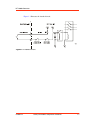
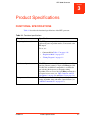
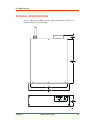
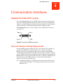
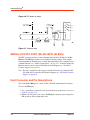
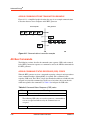
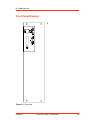
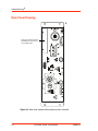
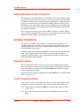
HFV 8000 Generator
Chapter
4
Communication Interfaces
GENERATOR USER PORT (15-PIN)
The 15-pin Generator User port on the HFV generator provides analog and digital
signals for controlling and monitoring the unit. This section describes the User port
connector, the minimal User port connections required to operate the unit, User port
cabling requirements, and detailed information about the User port signals.
The Generator User port is a 15-pin, shielded, female, subminiature-D connector
(see Figure 4-1).
Figure 4-1. Generator User port connector
User Port Interface Cabling Requirements
Connect the HFV generator’s User port to the system controller with a shielded, 15wire I/O cable. Shielded twisted-pair wiring may be used but is not mandatory.
Minimize signal losses by keeping the cable as short as possible. The maximum
recommended cable length between the HFV generator and the controller is 10 meters
(33 feet). Minimize interference from adjacent electrical equipment by terminating the
EMI shield in the cable to the metal shells of the cable’s connectors. Additionally, you
must tie the chassis of the HFV generator to a local earth ground through an
adequately sized copper grounding strap.
Note: Grounding the User port at the HFV generator reduces noise interference. To
avoid ground loop problems, you should typically ground only one end of the
User port cable.
5705072-F
Communication Interfaces
4-1